Implementation of Solar PV & Battery Storage
System of a Three Level NPC Inverter Using
Fuzzy Logic Controller
D.Alekhya1, K.Nagabhushanam2
1 PG student, Department of EEE , JNTU Anantapur, Andhra Pradesh, India 2 Lecturer, Department of EEE, JNTU Anantapur, Andhra Pradesh,India
ABSTRACT: The effect of linear imbalances and nonlinear loads on the voltage balance of the neutral-point clamped converter is described here. The Neutral-Point-Clamped inverters are used in the multilevel inverters for high power applications. A three level NPC inverter that can accommodate with solar photovoltaic (PV) and battery storage in a grid connected system is described here. This paper presents the Fuzzy Logic controller design philosophy of the proposed configuration and the theoretical framework of the proposed modulation technique. An incipient Fuzzy Logic controller for the proposed system is additionally presented in order to control the power delivery between the solar PV, battery and grid, which simultaneously provides Maximum power point tracking (MPPT) operation for the solar PV. A simulation model for the solar energy system has been developed using MATLAB/SIMULINK. The energy system performances under different scenarios, including battery charging and discharging with different levels of solar irradiation has been verified by carrying out simulation studies.
KEYWORDS: Fuzzy logic controller, MPPT, Solar PV.
I.INTRODUCTION
The solar energy is the clean and sustainable energy, with long life span and a high reliability. To avoid losses of transmission and contributing reductions of co2 emission in urban centers, this system can be located. Stand-alone systems
are independent of utility grids and commonly employed for satellites, space stations, unmanned aerial vehicles, and domestic applications. Such systems require storage elements to accommodate the intermittent generation of solar power. Over the years, research effort has been directed towards improving the power conversion efficiency .Traditionally, the two-port topology utilizes solar PV or wind energy applications, utilizing Maximum power from the source is one of the most important functions of the power electronic systems [3]–[5]. In three-phase applications, two types of power electronic configurations are commonly used to transfer power from the renewable energy resource to
the grid: single-stage and double-stage conversion. In the double-stage conversion for a PV system, the first stage is usually a dc/dc converter and the second stage is a dc/ac inverter.
In the single-stage connection, only one converter is needed to fulfill the double-stage functions, and hence the system will have a lower cost and higher efficiency, however, a more complex control method will be required. The current norm of the industry for high power applications is a three-phase, single stage PV energy systems by using a voltage-source converter (VSC) for power conversion
methods. For SPWM algorithm, the strategy to achieve neutral-point balance is by injecting appropriate zero-sequence signal to modulation signal [10], [11]. Due to the drawback of low dc voltage utilization, at present the studies mainly focus on the neutral-point balancing control strategies under the SVPWM algorithm.
A variety of strategies has been introduced to balance the neutral-point voltage under SVPWM. [12] and [17] alternatively select the positive and negative small vectors in every new switching cycle. However, these strategies can work only in the case of perfectly balanced load and would have difficulties to recover from load transients. Hysteresis-band control [4] is a most widely used closed-loop neutral-point voltage control strategy, which requires the knowledge of the current direction of each phase. Based on that information, the small vectors will move the neutral-point voltage in the direction opposite from the direction of unbalance.
This method avoids using conventional medium vectors which have an uncontrollable influence on the neutral-point voltage, but it has the drawback of low dc voltage utilization. The other approach is to improve the neutral-neutral-point voltage control strategy. As mentioned before, hysteresis-band control is the most widely used closed-loop control strategy, but its capability to restrain the low-frequency ripples is not satisfactory, especially at high modulation index condition. [16] Proposed a proportional control strategy based on small-signal model of neutral-point current, however, the capability to restrain the voltage ripples is also limited. This paper proposes a novel neutral-point voltage balance control strategy under the SVPWM algorithm, which not only can eliminate the voltage drifts, but also can minimize the voltage ripples.
The most commonly used multilevel topology is the diode clamped inverter, in which the diode is used as the clamping device to clamp the dc bus voltage so as to achieve steps in the output voltage. According to the original invention, the concept can be extended to any number of levels by increasing the number of capacitors. Early descriptions of this topology were limited to three-levels where two capacitors are connected across the dc bus resulting in one additional level. The additional level was the neutral point of the dc bus, so the terminology neutral point clamped (NPC) inverter was introduced.
II. PROPOSED TOPOLOGY TO INTEGRATE SOLAR PV AND BATTERY STORAGE AND ITS ASSOCIATED CONTROL
Proposed Topology to Integrate Solar PV and Battery
Storage Using a Three-Level Inverter
Fig.1 General diagram of a grid connected three-wire three-level inverter
Fig.2 Three level inverter NPC inverter
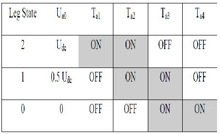
If each of the capacitors has a constant voltage of 0.5 Udc, then having the two upper switches on will give an
output voltage of Udc compared to level 0, switch 2 and 3 on will give 0.5 Udc and by having the two lower switches on, an
output voltage of 0 will occur. In addition to these three states there is a forbidden state where the first switch is on while the second is off.
Table 1: Bridge leg voltages at different combinations of switch states III. SPACE VECTOR PWM
Fig.3: Space vector diagram for a three-level converter
The reference voltage is defined as for a two-level converter there exist eight switching states. Two of these states are zero vectors, which gives seven different states that can be used to generate the wanted output voltage. A zero vector is when all the bridge legs are connected to the same point and all of the line-to-line voltages are zero. The six non-zero vectors have all the same amplitude, but different angles. By using these vectors in a correct manner the average of them will be the reference vector, by saying that the switching frequency is much higher than the fundamental frequency. A three-level converter has 27 vectors that can be used to create the desired voltage, with 19 different states, which can be seen in Fig 3.
It is starting off with vector 000 and moving on to 100 and so on, such that there is one switching transition between every new vector, for instance not to use the order 000, 200, 100 and 210. With this switching pattern all the vectors are being used, and the possibility of using the vector redundancy is maximized. The major drawback of using all of the vectors is that there will be an increase in the switching losses. At least should either 000 or 222 be removed since they give the same state. Hence other methods should be considered such that the switching losses may be reduced. The method that would require the least amount of commutations having the reference vector could be 222, 221, 211, 221 and 222 which is defined as modified space vector modulation according to [17], while the classical method is 222, 221, 211, 111, 211, 221 and 222. Even though the modified version has less switching transitions, it is concluded in [17] that the method produces more harmonics in the lower modulation area compared to classical space vector modulation, and thus the classical version is preferred.In [17] it is suggested that there are two switching patterns that could be used alternatively.
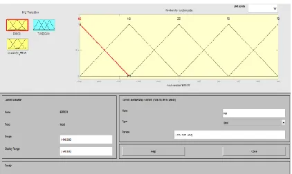
IV. FUZZY LOGIC CONTROLLER
Fuzzy logic uses fuzzy set theory, in which a variable is member of one or more sets, with a specified degree of membership. Fuzzy logic allow us to emulate the human reasoning process in computers, quantify imprecise information, make decision based on vague and in complete data, yet by applying a “defuzzification” process, arrive at definite conclusions[14-16].
The FLC mainly consists of three blocks
Fuzzification Inference Defuzzification
Fig. 4 Block Diagram of a Fuzzy Logic Controller RULES:
If input is NEGATIVE then output is POSITIVE If input is ZERO then output is ZERO
If input is POSITIVE then output is NEGATIVE
V. MATLAB MODEL OF THE SOLAR PV SYSTEM AND PROPOSED TECHNOLOGY
The solar PV system consists of PV module, NPC Three level inverters, MPPT control, Fuzzy Logic Control and a load. The single solar PV module consists of parallel solar cells, which is used to increasing the voltage and current. The output of solar PV module current is given to the input of a current controlled source. The single solar cell does not provide the maximum power, so the numbers of solar cells are connected in parallel and improve the output power. The output power system is connected to boost converter and to track the maximum power using Fuzzy logic controller The voltage supplied by the PV module does not have constant values, but it fluctuates according to the atmospheric conditions such as solar irradiance and temperature. The output voltage and current of the PV panel are measured and fed to the fuzzy based MPPT control unit for maximum power tracking. Based on the change of power with respect to the change of voltage
𝑑𝑝
𝑑𝑣and
Δ𝑑𝑝𝑑𝑣fuzzy system determines the voltage reference of The PWM (Pulse Width Modulation) signal.
TABLE II
PARAMETERS OF THE SIMULATED SYSTEM
Va Vb Lb Ci Cj Li Ls
50v 60v 5mH 1000uf 500uH 900uH
Three, series-connected PV modules are used in the simulation. The mathematical model of each of the PV units is given in [21] and used in the simulation where Iscis the short circuit current of the PV. In the simulation, it is assumed that Iscwill change with different irradiances. With a solar irradiation of 1000 W/m2, Iscis equal to 6.04 A and
the open circuit voltage of the PV panels will be
equal to Voc= 44V. The main parameters of the simulated system are given in Table II. G2 must be much more thanG1 in
order to achieve the MPPT condition and to have the flexibility to charge and discharge of the battery. Based on our experiments, any value more than 100 is suitable for this ratio. On the other hand, because the ratio of G2 /G1 will only
affect the short-vector selection, increasing this ratio wills not affect other results. This value has been selected to be 200 to 1 have good control on Vdc.
The role of Lb is to smooth the battery current, especially in the transient condition. A wide range of values are
acceptable for the inductor value, however, decreasing its value will increase the current overshoot of the battery. Also, its value is dependent of its adjacent capacitor value and its transient voltages. Due to the practical considerations (such as size and cost), the value of Lb is preferred to be low and has been chosen to be 5 mH based our simulation studies. Then at LCL
filter values are R=3Ω and L=14uf.
For theoretical purposes, two different scenarios have been simulated to investigate the effectiveness of the proposed topology and the control algorithm using a step change in the reference inputs under the following conditions:
1) The effect of a step change in the requested active underactive power to be transferred to the grid when the solar irradiance is assumed to be constant.
Simulations have been carried out using MATLAB/Simulink to verify the effectiveness of the proposed topology and control system. An LCL filter is used to connect the inverter to the grid. In a practical system, a slope controlled change in the reference input is usually used rather than a step change to diminish the risk of mathematical internal calculation errors when working with a limited precision microprocessor system and also to prevent the protection system activation. Furthermore, in practical situations, the inputs of the systems normally do not change instantaneously as a step change, such as the sun irradiation. With this practical application in mind, the proposed system is
requested active power to be transferred to the grid when the solar irradiance is assumed to be constant.
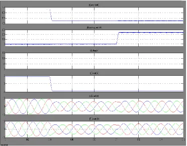
VI.SIMULATION RESULTS
Fig 6. Simulated results for the first scenario. (a) Active power injected to the grid. (b) Reactive power injected to the grid. (c) PV module DC voltage.(d) Battery current. (e) Inverter AC current. (f) Grid current.
Fig .6.1 (a)
Fig .6.1(b)
Fig 6.1 Total Harmonic Distortion of the Three Level NPC Output Current (a) Using PI Controller (b) Using Fuzzy Logic controller.
Fig.7.Simulated results for the second scenario.
(a) Active power injected to the grid. (b) PV module DC voltage.
(c) Battery currents. (d) Grid side currents.
(e) Grid side Phase.(i)voltage and its current
Fig.8. Simulated result for third scenario.
(a) Active power injected to the grid. (b) Battery current. (c) Grid side currents
Fig. 8(a) shows that the active power transmitted to the grid reduces and follows the requested active power.Fig.8 (b)shows the battery current which is a reduced power transmission to the grid with a constant PV output, the battery charging current is increased and finally fixed . Fig. 8(c) shows the ac inverter currents slowly decreasing and finally stays constant. During this simulation, the dc voltage is set to have a MPPT requirement. It is important to note that during the simulations, the dc bus is working under unbalanced condition because the battery voltage during the simulation is equal to 60 V, and therefore, this particular scenario will not allow equal capacitor voltages.
VII. CONCLUSION
In this paper, Design & Analysis of Solar PV & Battery Storage System of a Three – Level NPC Inverter Using Fuzzy Logic Controller has been implemented and simulated in MATLAB/Simulink.
Fuzzy Logic controller that can generate the correct ac voltage under unbalanced dc voltage conditions has been proposed. The proposed system as also been extant in order to control the power flow between solar PV, battery, and grid connected systems, and simultaneously MPPT operation is performed. The effectiveness of the proposed topology was tested using MATLAB/SIMULINK and results are presented. The MATLAB results demonstrate that the proposed system is able to control ac-side current, and battery charging and discharging currents at different levels of solar irradiation. The Proposed Fuzzy Logic control Strategy concludes that, the THD value of the inverter AC current decreases from 13.26% to 1.26%.This will result in lower cost, better efficiency and increased flexibility of power flow control.
REFERENCES
[2] Bragard, M., Soltau, N., Thomas, S. et al., 2010. "The Balance of Renewable Sources and User Demands in Grids:Power Electronics for Modular Battery Energy Storage Systems,"IEEE Transactions on Power Electronics, vol. 25, pp. 3049-3056.
[3] Hamid R., Teymour, Danny Sutanto, Kashem Muttaqi, P.ciufo, 2014. "Solar pv and battery storage integration using three level inverter,"IEE Trans. on energy conversion,vol. 29, no. 2 Jun.
[4] Hu, Y., Deng, Y., Liu, Q., and He, X. 2014. “Asymmetry three-level grid-connected current hysteresis control with varying bus voltage and virtual over-sample method,”IEEE Trans. Power Electron., vol. 29, no. 6, pp. 3214–3222,
[5] Jun. Konstantopoulos, C. and Koutroulis, E. 2014. “Global maximum power point tracking of flexible photovoltaic modules,”IEEE Trans. Power Electron., vol. 29, no. 6, pp. 2817–2828, Oct.
[6] Pou, J., Zaragoza, J., Ceballos, S., Saeedifard, M. and D. Boroyevich, 2012. “A carrier-based PWM strategy with zero-sequence voltage injection for a three-level neutralpoint-clamped converter,” IEEE Trans. Power Electron.,vol. 27, no. 2, pp. 642–651, Feb.
[7] Rodriguez, J., Bernet, S., Steimer, P. K. and I. E. Lizama, 2010. “A survey on neutral-point-clamped inverters,” IEEE Trans. Ind. Electron., vol. 57,no. 7, pp. 2219–2230, Jul.
[8] Huan-Liang Tsai, Ci-Siang Tu, and Yi-Jie Su, “Development of Generalized Photovoltaic Model Using MATLAB/Simulink,” Proceedings of the World Congress on Engineering and Computer Science 2008 WCECS 2008, October 22 - 24, 2008.
[9] Saikat Banerjee, Jeevananathan “Modeling of PV Array and Performance Enhancement by MPPT Algorithm,” International Journal of Computer Applications Vol.7, No.3, pp. 59-63, September 2010.
[10] Mohammed, Elgendy, Bashar Zahawi, and David Atkinson, “Assessment of Perturb and Observe MPPT Algorithm Implementation Techniques,” IEEE Transaction on Sustainable Energy, Vol. 3, No.1, Jan 2012.
[11] D. P. Hohm and M. E. Ropp, “Comparative Study of Maximum Power Point Tracking Algorithms using an Experimental,Programmable, MPPT Tested,” Proceedings of Photovoltaic Specialist Conference, pp. 1699–1702, 2009.
[12] Hussein, Muta, T. Hoshino, and Osakada, "Maximum Photovoltaic Power Tracking Algorithm for Rapidly Changing Atmospheric Conditions", IEEE Power .Generation, Transmission and Distribution, Vol.8, pp. 1359-1361, 2007.
[13] Slootweg and Zhao, “A Research on Photovoltaic Energy Controlling System With Maximum Power Point Tracking”, Proceedings of Power Conversion Conference, pp. 822–826, 2008.
[14] W.-C. So, Tse, and Lee, “Development of A Fuzzy Logic Controller for DC-DC Converters: Design, Computer Simulation, and Experimental Evaluation,” IEEE Trans. Power Electronics, Vol. 11, No. 1, pp. 24–32, Jan.2010.
[15] Basil M.Hamed, Mohammed, and El-Moghany, “Fuzzy Controller Design using Photovolatic Maximum Power Point Tracking,”International Journal of Advanced Research in Artifical Intelligence, Vol.1, No.3, 2012.
[16] Balasubramanian and Singaravelu, ”Fuzzy Logic Based Controller for A Standalone Hybrid Generation System Using Wind And Photovoltaic Energy,” International Journal of advances in Engineering & Technology, pp. 30-35, May 2012.
[17] J. Wei-dong, D. Shao-wu, C. Liu-chen, Y. Zhang, and Q. Zhao, “Hybrid PWM strategy of SVPWM and VSVPWM for NPC three-level voltage esource inverter” IEEE Trans. Power Electron., vol. 25, no. 10, pp. 2607–2619, Oct. 2010.
[18] J. Zaragoza, J. Pou, S. Ceballos, E. Robles, P. Ibaez, and J. L. Villate, “A comprehensive study of a hybrid modulation technique for the neutralpoint- clamped converter,” IEEE Trans. Ind. Electron., vol. 56, no. 2, pp. 294–304, Feb. 2009.
[19] Z. Jian-Yong, S. Zhang-Liang, M. Jun, and L.-f Wang, “An improved neutral-point voltage balancing algorithm for the npc three-level inverter based on virtual space vector PWM,” in Proc. Int. Conf. Elect. ControlEng., Jun. 2010, pp. 3283–3287.