DEFINITY®
Enterprise Communications Server
Release 6
Maintenance for R6vs/si
555-230-127
Comcode 108041948
Issue 1
All Rights Reserved Printed in U.S.A.
Notice
Every effort was made to ensure that the information in this book was complete and accurate at the time of printing. However, information is subject to change.
Your Responsibility for Your System’s Security
Toll fraud is the unauthorized use of your telecommunications system by an unauthorized party, for example, persons other than your company’s employees, agents, subcontractors, or persons working on your company’s behalf. Note that there may be a risk of toll fraud associated with your telecommunications system and, if toll fraud occurs, it can result in substantial additional charges for your telecommunications services. You and your system manager are responsible for the security of your system, such as programming and configuring your equipment to prevent unauthorized use. The system manager is also responsible for reading all installation, instruction, and system administration documents provided with this product in order to fully understand the features that can introduce risk of toll fraud and the steps that can be taken to reduce that risk. Lucent Technologies does not warrant that this product is immune from or will prevent unauthorized use of common-carrier telecommunication services or facilities accessed through or connected to it. Lucent Technologies will not be responsible for any charges that result from such unauthorized use. Lucent Technologies Fraud Intervention
If you suspect that you are being victimized by toll fraud and you need technical support or assistance, call Technical Service Center Toll Fraud Intervention Hotline at 1 800 643-2353.
Federal Communications Commission Statement
Part 15: Class B Statement. This equipment has been tested and found to comply with the limits for a Class B digital device, pursuant to Part 15 of the FCC Rules. These limits are designed to provide reasonable protection against harmful interference in a residential installation. This equipment generates, uses, and can radiate radio-frequency energy and, if not installed and used in accordance with the instructions, may cause harmful interference to radio communications. However, there is no guarantee that interference will not occur in a particular installation. If this equipment does cause harmful interference to radio or television reception, which can be determined by turning the equipment off and on, the user is encouraged to try to correct the interference by one or more of the following measures:
• Reorient the receiving television or radio antenna where this may be done safely.
• To the extent possible, relocate the receiver with respect to the telephone equipment.
• Where the telephone equipment requires ac power, plug the telephone into a different ac outlet so that the telephone equipment and receiver are on different branch circuits. Part 68: Network Registration Number. This equipment is registered with the FCC in accordance with Part 68 of the FCC Rules. It is identified by FCC registration number AS593M-11185-MF-E.
Part 68: Answer-Supervision Signaling. Allowing this equipment to be operated in a manner that does not provide proper answer-supervision signaling is in violation of Part 68 rules. This equipment returns answer-supervision signals to the public switched network when:
• Answered by the called station • Answered by the attendant
• Routed to a recorded announcement that can be administered by the CPE user
This equipment returns answer-supervision signals on all DID calls forwarded back to the public switched telephone network. Permissible exceptions are:
• A call is unanswered • A busy tone is received • A reorder tone is received
DEFINITY is a registered trademark of Lucent Technologies in the U.S. and throughout the world.
AUDIX is a registered trademark of Lucent Technologies. Ordering Information
Call: Lucent Technologies Publications Center
Voice 1 800 457-1235 International Voice 317 361-5353 Fax 1 800 457-1764 International Fax 317 361-5355 Write: Lucent Technologies Publications Center
P.O. Box 4100 Crawfordsville, IN 47933 Order: Document No. 555-230-127
Comcode 108041948 Issue 1, August 1997
For additional documents, refer to the section entitled, “Related Documents” in “About This Book.”
You can be placed on a Standing Order list for this and other documents you may need. Standing Order will enable you to automatically receive updated versions of individual documents or document sets, billed to account information that you provide. For more information on Standing Orders, or to be put on a list to receive future issues of this document, please contact the Lucent Technologies Publications Center.
Warranty
Lucent Technologies provides a limited warranty on this product. Refer to the “Limited use Software License Agreement” card provided with your package.
European Union Declaration of Conformity
Lucent Technologies Business Communications Systems declares that XXX equipment specified in this document conforms to the referenced European Union (EU) Directives and Harmonized Standards listed below: EMC Directive 89/336/EEC
Low Voltage Directive 73/23/EEC
The “CE” mark affixed to the equipment means that it conforms to the above Directives.
Disclaimer
Intellectual property related to this product and registered to AT&T Corporation has been transferred to Lucent Technologies Incorporated. Any references within this text to American Telephone and Telegraph Corporation or AT&T should be interpreted as references to Lucent Technologies Incorporated. The exception is cross references to books published prior to December 31, 1996, which retain their original AT&T titles.
Heritage
Lucent Technologies - formed as a result of AT&T’s planned restructuring - designs, builds, and delivers a wide range of public and private networks, communication systems and software, consumer and business telephone systems, and microelectronics components. The world-renowned Bell Laboratories is the research and development arm for the company. Acknowledgment
Maintenance for R6vs/si 555-230-127 August 1997 Contents
Page iii
Contents
Contents iii
About This Book xxi
■ General xxi
■ Conventions Used in This Document xxii
■ Organization xxiii
■ Safety Precautions xxiv
■ Class 1 Laser Device xxv
■ Security Issues xxv
■ Standards Compliance xxv
■ Electromagnetic Compatibility Standards xxvi ■ Trademarks and Service Marks xxvii
■ Related Documents xxviii
■ Federal Communications Commission Statement xxxi
1
Maintenance Architecture 1-1■ Maintenance Objects 1-1
■ Alarm and Error Reporting 1-2
■ Maintenance Testing 1-2
■ Protocols 1-3
■ Service Codes 1-17
■ Facility Interface Codes 1-18 ■ Multimedia Interface (MMI) 1-19
2
Circuit Packs and Power 2-1■ Circuit Packs 2-1
■ Power 2-6
3
Management Terminals 3-1■ General 3-1
■ Management Terminals 3-1
■ System Login Procedure 3-3
■ Switch-Based Bulletin Board 3-24 ■ System Logoff Procedure 3-26
■ DEC VT220 Terminal 3-27
4
Initialization and Recovery 4-1Maintenance for R6vs/si 555-230-127 August 1997 Contents
Page iv
■ Reset System 2 (System Cold Start
Without Translations Loading) 4-2
■ Reset System 3 (System Cold Start
With Translations Loading) 4-3
■ Reset System 4 (System Reboot) 4-4 ■ Reset System 5 (System Reboot and
Run All 24-Hour Tests) 4-5
■ Reset System Interchange (High or
Critical Reliability Systems Only) 4-7
■ Procedure for SPE-Down Mode 4-8 ■ Procedure for Duplication Interface —
Processing Element Communication Down 4-11
5
Routine Maintenance Procedures 5-1■ Suppress Alarm Origination [y] 5-1 ■ Handling Control Circuit Packs 5-1 ■ TN790 Processor Circuit Pack (Memory) 5-4
■ Removing Power 5-4
■ Restoring Power 5-6
■ Troubleshooting Control Cabinet Power Units 5-9 ■ Replacing Components (Release 5vs or Later) 5-10
■ System Backup 5-14
■ Software Upgrade 5-18
■ Preventive Maintenance Procedures 5-36
■ System Features 5-37
■ Troubleshooting Backplane Voltage Problems 5-62 ■ Troubleshooting Multimedia Call Handling (MMCH) 5-62 ■ Install DS1 CPE Loopback Jack (T1 Only) 5-69
6
Reliability Systems: A Maintenance Aid 6-1■ General 6-1
■ Reliability Options 6-2
■ Duplicated Hardware 6-4
■ Duplication Concepts 6-8
■ System Technician Commands for
High and Critical Reliability Systems 6-13
Maintenance for R6vs/si 555-230-127 August 1997 Contents
Page v
■ Procedure for Installing/Replacing the
Inter-Cabinet Cable 6-31
■ Blocking Standby SPE Maintenance
Activities for System Testing 6-32
7
LED Interpretation 7-1■ General 7-1
■ Processor and Maintenance Circuit
Pack LEDs 7-1
■ Duplication Interface Circuit Pack LEDs 7-3
■ Attendant Console LEDs 7-5
■ Cabinet Power Unit LEDs 7-5
■ Power Distribution Unit LEDs 7-5 ■ Control and Port Circuit Pack Status LEDs 7-5
8
Maintenance Commands andTrouble-Clearing Aids 8-1
■ busyout access-endpoint 8-1
■ busyout board 8-2
■ busyout cdr-link 8-4
■ busyout data-module 8-5
■ busyout journal-printer 8-6
■ busyout link 8-8
■ busyout mis 8-9
■ busyout modem-pool 8-10
■ busyout packet-control 8-11
■ busyout pms-link 8-13
■ busyout port 8-14
■ busyout pri-endpoint 8-15
■ busyout sp-link 8-16
■ busyout spe-standby 8-17
■ busyout station 8-19
■ busyout tdm 8-20
■ busyout tone-clock 8-21
■ busyout trunk 8-22
■ cancel hardware-group 8-23
■ change circuit-packs 8-24
Maintenance for R6vs/si 555-230-127 August 1997 Contents
Page vi
■ change system-parameters maintenance 8-28
■ clear audits 8-39
■ clear errors 8-39
■ clear interface 8-40
■ clear isdn-testcall 8-40
■ clear link 8-40
■ clear mst 8-41
■ clear pkt 8-41
■ clear port 8-41
■ copy update-file 8-41
■ disable administered-connection 8-42
■ disable mst 8-43
■ disable suspend-alm-orig 8-43 ■ disable synchronization-switch 8-43
■ disable test-number 8-44
■ display alarms 8-44
■ display cabinet 8-49
■ display communication-interface 8-51
■ display disabled-tests 8-56
■ display errors 8-57
■ display events 8-63
■ display initcauses 8-65
■ display memory-configuration 8-71
■ display port 8-73
■ display synchronization 8-74 ■ display system-parameters maintenance 8-76
■ display time 8-86
■ download update-file 8-88
■ enable administered-connection 8-92
■ enable mst 8-92
■ enable suspend-alm-orig 8-93 ■ enable synchronization-switch 8-94
■ enable test-number 8-94
■ format card-mem 8-94
Maintenance for R6vs/si 555-230-127 August 1997 Contents
Page vii
■ list configuration 8-97
■ list config software-version 8-100
■ list disabled-mos 8-104
■ list history 8-105
■ list isdn-testcall 8-107
■ list marked-ports 8-108
■ list measurements 8-109
■ list mst 8-113
■ list suspend-alm-orig 8-145
■ list testcalls 8-146
■ mark port 8-150
■ monitor bcms 8-151
■ monitor health 8-155
■ monitor security-violations 8-158
■ monitor system 8-160
■ monitor traffic 8-165
■ monitor trunk 8-167
■ recycle carrier 8-168
■ refresh spe-standby 8-170
■ release access-endpoint 8-170
■ release board 8-171
■ release cdr-link 8-173
■ release data-module 8-174
■ release journal-printer 8-175
■ release link 8-176
■ release mis 8-177
■ release modem-pool 8-178
■ release packet-control 8-179
■ release pms-link 8-180
■ release port 8-181
■ release pri-endpoint 8-182
■ release sp-link 8-183
■ release spe-standby 8-185
■ release station 8-186
Maintenance for R6vs/si 555-230-127 August 1997 Contents
Page viii
■ release tone-clock 8-188
■ release trunk 8-189
■ reset board 8-190
■ reset interface 8-191
■ reset maintenance 8-192
■ reset spe-standby 8-193
■ reset system 8-193
■ restore announcements 8-196
■ resume hardware-group 8-198
■ save announcements 8-198
■ save translation 8-201
■ set expansion-link 8-202
■ set options 8-203
■ set signaling-group 8-209
■ set synchronization 8-209
■ set tdm 8-210
■ set time 8-211
■ set tone-clock 8-212
■ set vector 8-212
■ status access-endpoint 8-214 ■ status administered-connection 8-216
■ status attendant 8-217
■ status audits 8-218
■ status bri-port 8-226
■ status card-mem 8-233
■ status cdr-link 8-236
■ status cleared-alarm-notif 8-237
■ status conference 8-238
■ status data-module 8-274
■ status hardware-group 8-275
■ status health 8-277
■ status interface 8-279
■ status isdn-testcall 8-280
■ status journal-link 8-282
Maintenance for R6vs/si 555-230-127 August 1997 Contents
Page ix
■ status pms-link 8-290
■ status pri-endpoint 8-291
■ status processor-channel 8-293 ■ status signaling-group 8-295
■ status sp-link 8-297
■ status station 8-298
■ status synchronization 8-300
■ status system 8-301
■ status trunk 8-310
■ status tsc-administered 8-312
■ status tti 8-313
■ test access-endpoint 8-316
■ test alarms 8-317
■ test analog-testcall 8-322
■ test board 8-325
■ test card-mem 8-327
■ test cdr-link 8-331
■ test customer-alarm 8-333
■ test data-module 8-334
■ test ds1-loop 8-336
■ test duplication-interface 8-338 ■ test eda-external-device-alrm 8-340
■ test environment 8-343
■ test hardware-group 8-346
■ test inads-link 8-352
■ test interface 8-354
■ test isdn-testcall 8-355
■ test journal-printer 8-357
■ test led 8-359
■ test link 8-361
■ test maintenance 8-362
■ test memory 8-365
■ test modem-pool 8-366
■ test network-control 8-369
Maintenance for R6vs/si 555-230-127 August 1997 Contents
Page x
■ test pkt 8-373
■ test pms-link 8-375
■ test port 8-378
■ test pri-endpoint 8-379
■ test processor 8-382
■ test shadow-link 8-383
■ test signaling-group 8-386
■ test sp-link 8-387
■ test spe-standby 8-389
■ test station 8-391
■ test synchronization 8-393
■ test tdm 8-396
■ test tone-clock 8-397
■ test trunk 8-399
■ test tsc-administered 8-401
■ upgrade software 8-403
9
Packet Bus Fault Isolation and Correction 9-1■ General 9-1
■ Remote Maintenance versus On-Site Maintenance 9-2 ■ Tools for Packet Bus Fault Isolation and Correction 9-3
■ Packet Bus 9-3
■ Circuit Packs That Use the Packet Bus 9-5 ■ Maintenance of the Packet Bus 9-7 ■ The Maintenance/Test Circuit Pack (TN771D) 9-10 ■ Packet Bus Fault Isolation Flowchart 9-19 ■ Packet Bus Fault Correction 9-24
10
Maintenance Object Repair Procedures 10-1■ Escalation Procedures 10-1
■ Cabling Precautions 10-1
■ 12V-PWR (12 Volt Power Supply) 10-3 ■ ABRI-PORT (ASAI ISDN-BRI Port) 10-6
■ AC-POWER 10-7
Maintenance for R6vs/si 555-230-127 August 1997 Contents
Page xi
■ ADX16D-B (16 Port AUDIX Circuit Pack) 10-27 ■ ADX16A-BD (AUDIX Circuit Pack) 10-28 ■ ADX16D-P (16-Port AUDIX Digital Port) 10-29 ■ ADX16A-PT (AUDIX Analog Line/Control Link) 10-36
■ ALARM-PT (ALARM PORT) 10-43
■ ANL-16-L (16-Port Neon Analog Line) 10-44 ■ ANL-BD (Analog Line Circuit Pack) 10-63 ■ ANL-LINE (8-Port Analog Line),
ANL-NE-L (8-Port Neon Analog Line) 10-64
■ ANN-BD (Announcement Circuit Pack) 10-84 ■ ANN-PT (Announcement Port) 10-105
■ ANNOUNCE (Announce) 10-119
■ ASAI-BD (Multi-Application Platform Board) 10-124
■ ASAI-EPT 10-126
■ ASAI-PT 10-134
■ ASAI-RES/E-DIG-RES (TN800 reserve slot) 10-144 ■ BRI-BD/LGATE-BD (ISDN-BRI Line Circuit Pack) 10-145
■ BRI-DAT (ISDN-BRI) 10-153
■ BRI-PORT (ISDN-BRI Port),
ABRI-PORT (ASAI ISDN-BRI Port) 10-154
■ BRI-SET, ASAI-ADJ, BRI-DAT 10-178 ■ CABINET (Cabinet Sensors) 10-209 ■ CAP-MEM (Memory Card Capacity) 10-223 ■ CARD-MEM (Memory Card) 10-226 ■ CARR-POW (Carrier Port Power Unit)
for AC-Powered Systems 10-245
■ CARR-POW (Carrier Port Power Unit)
for DC-Powered Systems 10-262
■ CLSFY-BD (Call Classifier Circuit Pack) 10-277 ■ CLSFY-PT (Call Classifier Port) 10-278 ■ CO-BD (Central Office Trunk Circuit Pack) 10-283
■ CO-DS1 (DS1 CO Trunk) 10-284
■ CO-TRK (CO Trunk) 10-301
Maintenance for R6vs/si 555-230-127 August 1997 Contents
Page xii
■ DATA-CON (Network Control Driver) 10-377
■ DAT-LINE (Data Line) 10-379
■ DC-POWER 10-387
■ DETR-BD 10-391
■ DID-BD (Direct Inward Dial Trunk Circuit Pack) 10-392 ■ DID-DS1 (DS1 DID Trunk) 10-393
■ DID-TRK (DID Trunk) 10-405
■ DIG-BD (Digital Line Circuit Pack) 10-422 ■ DIG-LINE (Digital Line) 10-423 ■ DIOD-DS1 (DS1 DIOD Trunk) 10-450 ■ DIOD-TRK (DIOD Trunk), DIOD-BD
(DIOD Circuit Pack) [G1.2SE] 10-462
■ DIOD-TRK (DIOD Trunk) [G1.2SE] 10-463
■ DLY-MTCE (MO-DAILY) 10-474
■ DS1-BD (DS1 Interface Circuit Pack) 10-475 ■ DT-LN-BD (Data Line Circuit Pack) 10-547 ■ DTMR-PT [Dual Tone Multifrequency Port (TTR)] 10-548 ■ DUPINT (Duplication Interface Circuit Pack) 10-553 ■ E-DIG-BD (Multi Application Platform Board) 10-570 ■ E-DIG-RES (TN800 reserve slot) 10-572 ■ E-DIG-STA (Emulated Digital Line) 10-573
■ EMG-XFER 10-583
■ EPN-SNTY (EPN Sanity Audit) 10-587
■ ERR-LOG (Error Log) 10-590
■ ETR-PT (Enhanced Tone Receiver Port) 10-592 ■ EXP-INTF (Expansion Interface Circuit Pack) 10-598 ■ EXP-LINK (Expansion Interface Link) 10-647 ■ EXT-DEV ADMIN? N (External Device Alarm) 10-649 ■ EXT-DEV ADMIN? Y (External Device Alarm) 10-653 ■ FL-DATA (Flash Data Consistency) 10-657 ■ GPTD-PT [General Purpose Tone
Detector Port (CPTR)] 10-672
■ HYB-BD (Hybrid Line Circuit Pack) 10-673 ■ HYB-LINE (Hybrid Line) 10-674
■ INADS (INADS Link) 10-699
Maintenance for R6vs/si 555-230-127 August 1997 Contents
Page xiii
■ ISDN-PLK (ISDN-PRI Signaling Link Port) 10-709 ■ ISDN-SGR (ISDN-PRI Signaling Group) 10-718 ■ ISDN-TRK (DS1 ISDN Trunk) 10-745 ■ LOG-SVN (Login Security Violation) 10-772 ■ JNL-PRNT (Journal Printer Link) 10-775
■ LGATE-AJ 10-776
■ LGATE-BD 10-776
■ LGATE-PT 10-776
■ MAINT (EPN Maintenance Circuit Pack) 10-777
■ MEM-BD (Memory) 10-795
■ MEMORY 10-801
■ MET-BD (MET Line Circuit Pack) 10-802
■ MET-LINE (MET Line) 10-803
■ MIS (Management Information System) 10-827 ■ MODEM-BD (Modem Pool Circuit Pack) 10-828 ■ MODEM-PT (Modem Pool Port) 10-829
■ MMI-BD 10-845
■ MMI-LEV (Multimedia Interface Resource Level) 10-854
■ MMI-PT 10-857
■ MMI-SYNC 10-863
■ M/T-ANL (Maintenance/Test Analog Port) 10-865 ■ M/T-BD (Maintenance/Test Circuit Pack) 10-875 ■ M/T-DIG (Maintenance/Test Digital
Port) [G3iV1-1.286, G3iV2-386] 10-876
■ M/T-PKT (Maintenance/Test Packet Bus Port) 10-889 ■ OPS-LINE (DS1 OPS Line) 10-894 ■ PDMODULE, TDMODULE (Data Module) 10-907 ■ PE-BCHL (PRI Endpoint Port) 10-927 ■ PI-BD (Processor Interface Circuit Pack) 10-946 ■ PI-LINK (Processor Interface Link) 10-953 ■ PI-PT (Processor Interface Port) 10-969 ■ PI-SCI (System Communication Interface) 10-974
■ PKT-BUS (Packet Bus) 10-982
Maintenance for R6vs/si 555-230-127 August 1997 Contents
Page xiv
■ POWER (Battery & Battery Charger)
for AC-Powered Systems 10-1022
■ POWER (Battery & Battery Charger
for DC-Powered Systems 10-1031
■ PR-MAINT (Maintenance Processor
[TN790 RISC Systems]) 10-1035
■ PR-MAINT (Maintenance Processor) 10-1050 ■ PR-MEM (TN790 RISC Memory) 10-1062 ■ PRI-CDR/SEC-CDR (PRI-CDR Link) 10-1071 ■ PROC-SAN (Process Sanity Audits) 10-1078 ■ PROCR (Processor Circuit Pack) 10-1079 ■ PROCR (TN790 RISC Processor Circuit Pack) 10-1086 ■ RING-GEN (Analog Ring Generator) 10-1094 ■ S-SYN-BD (Speech Synthesis Circuit Pack) 10-1103 ■ S-SYN-PT (Speech Synthesis Port) 10-1104 ■ SEC-CDR (SEC-CDR Link Maintenance) 10-1117 ■ SHDW-CIR (Common Shadow Circuit) 10-1118 ■ SHDW-LNK (Memory Shadowing Link) 10-1125 ■ SPE-SELEC (SPE Select Switch) 10-1143 ■ STBY-SPE (Standby SPE) 10-1147 ■ STRAT-3 (Stratum 3 Clock)] 10-1184 ■ SVC-SLOT (Service Slot) 10-1196 ■ SW-CTL (Switch Control) 10-1198 ■ SYNC (Synchronization) 10-1212 ■ SYS-PRNT (System Printer) 10-1224
■ SYSTEM (System) 10-1230
■ TAPE (Tape Unit) [G3iV1.1-286] 10-1232 ■ TAPE-DAT (Tape Consistency) 10-1262 ■ TBRI-BD (TN2185
ISDN Trunk-Side BRI) 10-1273
■ TBRI-PT (TN2185
ISDN Trunk-Side BRI Port) 10-1281
■ TBRI-TRK (TN2185
ISDN Trunk-Side BRI) 10-1301
■ TDMODULE (Trunk Data Module) 10-1311
■ TDM-BUS (TDM Bus) 10-1312
Maintenance for R6vs/si 555-230-127 August 1997 Contents
Page xv
■ TIE-BD (Tie Trunk Circuit Pack) 10-1347 ■ TIE-DS1 (DS1 Tie Trunk) 10-1348
■ TIE-TRK (Tie Trunk) 10-1366
■ TONE-BD (Tone-Clock Circuit Pack) 10-1391 ■ TONE-PT (Tone Generator) 10-1411 ■ TSC-ADM (Administered Temporary
Signaling Connections) 10-1422
■ TTR-LEV (TTR Level) 10-1428
■ UDS1-BD (UDS1 Interface Circuit Pack) 10-1433
■ VC-BD 10-1523
■ VC-DSPPT 10-1527
■ VC-LEV (Voice Conditioner
DSP Port Level) 10-1536
■ VC-SUMPT 10-1539
■ WAE-PORT (Wideband Access Endpoint Port) 10-1544 ■ XXX-BD (Common Port Circuit Pack) 10-1551
A
Error Messages A-1■ Error Messages from Chapter 8,
Maintenance Commands A-1
■ busyout access-endpoint A-1
■ busyout board A-2
■ busyout cdr-link A-3
■ busyout data-module A-4
■ busyout journal-printer A-5
■ busyout link A-5
■ busyout mis A-6
■ busyout modem-pool A-7
■ busyout packet-control A-8
■ busyout pms-link A-8
■ busyout port A-9
■ busyout pri-endpoint A-10
■ busyout sp-link A-11
■ busyout spe-standby A-11
■ busyout station A-12
■ busyout tdm A-13
Maintenance for R6vs/si 555-230-127 August 1997 Contents
Page xvi
■ busyout trunk A-15
■ cancel hardware-group A-16
■ change circuit-packs A-16
■ change synchronization A-17
■ clear audits A-17
■ clear errors A-17
■ clear interface A-18
■ clear isdn-testcall A-19
■ clear link A-20
■ clear mst A-21
■ clear pkt A-21
■ clear port A-22
■ copy update-file A-22
■ disable administered-connection A-23
■ disable mst A-24
■ disable suspend-alm-orig A-24 ■ disable synchronization-switch A-25
■ disable test-number A-25
■ display alarms A-26
■ display disabled-tests A-28
■ display errors A-28
■ display events A-33
■ display initcauses A-33
■ display memory-configuration A-33
■ display port A-34
■ display synchronization A-34 ■ display system-parameters maintenance A-35
■ display time A-35
■ download update-file A-35
■ enable administered-connection A-38
■ enable mst A-39
■ enable suspend-alm-orig A-39 ■ enable synchronization-switch A-40
■ enable test-number A-40
Maintenance for R6vs/si 555-230-127 August 1997 Contents
Page xvii
■ get vector A-41
■ list disabled-mos A-42
■ list history A-42
■ list isdn-testcall A-43
■ list marked-ports A-43
■ list measurements A-44
■ list mst A-44
■ list suspend-alm-orig A-45
■ list testcalls A-45
■ mark port A-46
■ monitor bcms A-47
■ monitor health A-47
■ monitor system A-48
■ monitor traffic A-49
■ monitor trunk A-49
■ recycle carrier A-50
■ refresh spe-standby A-51
■ release access-endpoint A-51
■ release board A-52
■ release cdr-link A-53
■ release data-module A-54
■ release journal-printer A-55
■ release link A-55
■ release mis A-56
■ release modem-pool A-57
■ release packet-control A-58
■ release pms-link A-58
■ release port A-59
■ release pri-endpoint A-60
■ release sp-link A-61
■ release spe-standby A-62
■ release station A-62
■ release tdm A-63
■ release tone-clock A-64
Maintenance for R6vs/si 555-230-127 August 1997 Contents
Page xviii
■ reset board A-66
■ reset interface A-67
■ reset maintenance A-69
■ reset spe-standby A-70
■ reset system A-70
■ restore announcements A-71
■ resume hardware-group A-72
■ save announcements A-73
■ save translation A-74
■ set expansion-link A-75
■ set options A-76
■ set signaling-group A-78
■ set synchronization A-78
■ set tdm A-79
■ set time A-80
■ set tone-clock A-81
■ set vector A-83
■ status access-endpoint A-84
■ status administered-connection A-85
■ status attendant A-86
■ status audits A-86
■ status bri-port A-87
■ status card-mem A-88
■ status cdr-link A-89
■ status cleared-alarm-notif A-89
■ status conference A-89
■ status data-module A-89
■ status hardware-group A-90
■ status health A-91
■ status interface A-91
■ status isdn-testcall A-92
■ status journal-link A-93
■ status link A-94
■ status logins A-94
Maintenance for R6vs/si 555-230-127 August 1997 Contents
Page xix
■ status packet-control A-95
■ Ostatus periodic-scheduled A-96
■ status pms-link A-96
■ status pri-endpoint A-97
■ status processor-channel A-97
■ status signaling-group A-98
■ status sp-link A-99
■ status station A-99
■ status synchronization A-100
■ status system A-100
■ status trunk A-101
■ status tsc-administered A-102
■ status tti A-103
■ test access-endpoint A-103
■ test alarms A-104
■ test analog-testcall A-108
■ test board A-110
■ test card-mem A-111
■ test cdr-link A-112
■ test customer-alarm A-113
■ test data-module A-113
■ test ds1-loop A-114
■ test duplication-interface A-116 ■ test eda-external-device-alrm A-117
■ test environment A-117
■ test hardware-group A-117
■ test inads-link A-120
■ test interface A-120
■ test isdn-testcall A-122
■ test journal-printer A-123
■ test led A-124
■ test link A-124
■ test maintenance A-125
■ test memory A-126
Maintenance for R6vs/si 555-230-127 August 1997 Contents
Page xx
■ test network-control A-129
■ test packet-control A-131
■ test pkt A-131
■ test pms-link A-132
■ test port A-133
■ test pri-endpoint A-134
■ test processor A-135
■ test shadow-link A-136
■ test signaling-group A-137
■ test sp-link A-138
■ test spe-standby A-138
■ test station A-139
■ test synchronization A-140
■ test tdm A-141
■ test tone-clock A-142
■ test trunk A-143
■ test tsc-administered A-144
■ upgrade software A-145
About This Book
Page xxi General
Maintenance for R6vs/si 555-230-127 August 1997
About This Book
General
This book has the information needed to monitor, test, and maintain DEFINITY® Enterprise Communications Server Release 6 Systems and covers many of the faults and troubles that can occur in the system. Most maintenance requirements are simple procedures due to the modular, self-testing nature of the system.
This document covers information related to DEFINITY ECS Release 6.1, including all incremental releases.
Simple, traditional troubleshooting methods are sometimes sufficient to locate and clear faults. The traditional methods include terminal substitution, visual inspections, continuity checks, and clarification of operating procedures with users.
The information in this book is intended for use by:
■ A maintenance technician dispatched to a DEFINITY System site in
response to a trouble alarm or a user trouble report,
■ A maintenance technician located at a remote maintenance facility, or
■ The user’s assigned maintenance technician. The technician is expected
Maintenance for R6vs/si 555-230-127 August 1997 About This Book
Page xxii Conventions Used in This Document
Each DEFINITY System has a user-designated System Manager who is
responsible for administration of the system. The maintenance technician should work closely with the user’s System Manager.
This book is not intended to solve all levels of troubles. It is limited to troubles that can be solved by using the Alarm Log, Error Log, trouble-clearing procedures, maintenance tests, and traditional troubleshooting methods. If the trouble still has not been resolved, it the responsibility of the maintenance technician to escalate the problem to a higher level of technical support. Escalation should conform to the procedures in the Technical and Administration Escalation Plan.
When features, screen displays, equipment, or operations differ between system types, for example, Generic 3 V4, Release 5si, or Release 5si + memory, these differences are clearly identified by use of the following indicators: “[G3V4]”, “[R5si]”, or “[R5 si + memory].”
Conventions Used in This Document
The following conventions are used in this document:
■ DEFINITY Systems are called G3V4, Release 5; Release 5vs, Release 5si,
Release 5si + memory, and Release 6.
■ All occurrences of G3siV4, G3siV4+m, Release 5si, and Release 5 si +
memory are called Release 5si unless a specific configuration is required to differentiate among product offerings.
■ All occurrences of R5 without a suffix following the “5” refer to Release 5si,
and Release 5si + memory.
■ A component of a DEFINITY System, such as a circuit pack, occurring
without a reference to any specific system, is part of G3V4 or Release 5.
■ The term “ASAI” is synonymous with the newer CallVisor ASAI.
■ All physical dimensions in this book are in English (Foot Pound Second)
(FPS) followed by the metric Centimeter Grams Second (CGS) in parenthesis. Wire gauge measurements are in AWG followed by the diameter in millimeters in parenthesis.
■ Admonishments used in this book are as follows:
!
CAUTION:
This sign is used to indicate possible harm to software, possible loss of data, or possible service interuptions.
!
WARNING:
Maintenance for R6vs/si 555-230-127 August 1997 About This Book
Page xxiii Organization
!
DANGER:
This sign is used to indicate possible harm or injury to people.
Organization
This book is organized into two volumes: volume 1 contains Chapters 1 through 9, and volume 2 contains Chapter 10.
■ Chapter 1, ‘‘Maintenance Architecture’’ describes the system’s design
and maintenance strategy.
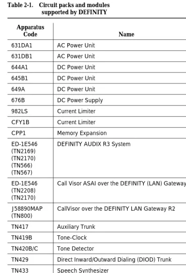
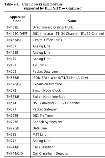
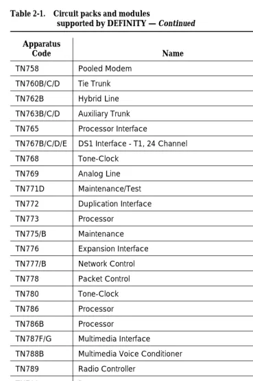
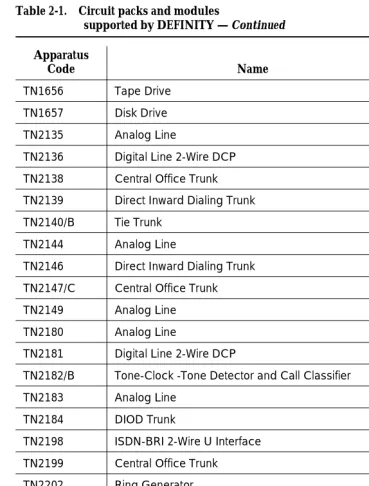
■ Chapter 2, ‘‘Circuit Packs and Power’’ describes DEFINITY circuit
packs. It also explains how power is supplied to the system.
■ Chapter 3, ‘‘Management Terminals’’ describes the various
management terminals that can be used on the system and how to set up the terminals.
■ Chapter 4, ‘‘Initialization and Recovery’’ describes the various reset
and reboot processes, and discusses how these processes are used to perform maintenance and to recover systems or subsystems that are out of service.
■ Chapter 5, ‘‘Routine Maintenance Procedures’’ discusses common
maintenance tasks, including: removing and installing circuit packs, removing and restoring power, performing system backups, upgrading software, and various testing and troubleshooting procedures.
■ Chapter 6, ‘‘Reliability Systems: A Maintenance Aid’’ provides detailed
hardware and functional descriptions as well as additional repair strategy (in addition to the procedures provided in this document) for Standard, High, and Critical Reliability systems.
■ Chapter 7, ‘‘LED Interpretation’’ is a quick reference to interpreting
circuit pack LEDs.
■ Chapter 8, ‘‘Maintenance Commands and Trouble-Clearing Aids’’ has
the maintenance commands, and explains how to use these commands using the management terminal. Specific command syntax plus typical forms and display output are also given in the chapter.
■ Chapter 9, ‘‘Packet Bus Fault Isolation and Correction’’ describes
Pack Bus maintenance and the interactions of the bus with Packet circuit packs. The chapter also discusses how Packet Bus faults are isolated and corrected.
■ Chapter 10, ‘‘Maintenance Object Repair Procedures’’ has specific
Maintenance for R6vs/si 555-230-127 August 1997 About This Book
Page xxiv Safety Precautions
run the tests are given and a brief description of each test. Explanations of error codes associated with each test are given, as are specific
maintenance procedures to be used to resolve each problem.
Each MO is described in a separate section of Chapter 10, ‘‘Maintenance Object Repair Procedures’’. The individual sections are labeled with the name of the MO exactly as the name appears in the Alarm Log; for example, MAINT (for
Maintenance circuit pack). The only exception is the MO name for Common Port Circuit Pack maintenance which is XXX-BD. The XXX-BD section contains a set of common tests used by certain circuit packs listed in the section. The common portion of these circuit packs is the generic hardware that interfaces with the Time Division Multiplex (TDM) Bus.
Lucent Technologies listens carefully to its readers. The organization of this book is a direct result of user feedback. Your feedback is important. Use the feedback form at the back of this book to send your comments to Lucent Technologies.
Safety Precautions
When performing maintenance or translation procedures on the system, users must observe certain precautions. Observe all caution, warning, and danger statements to prevent loss of service, possible equipment damage, and possible personal injury. In addition, the following precautions regarding electromagnetic interference (EMI) and static electricity must be observed:
Electromagnetic Interference
This equipment generates, uses, and can radiate radio frequency energy. Electromagnetic fields radiating from the switch may cause noise in the
customer’s equipment. If the equipment is not installed and used in accordance with the instruction book, radio interference may result.
!
WARNING:
To maintain the EMI integrity of the system, maintenance personnel must ensure that all cabinet panels, covers, and so forth, are firmly secured before leaving the customer’s premises.
Static Electricity
To prevent or reduce electrostatic discharge (ESD), always attach wrist grounding straps before working on switch components or handling circuit packs.
!
CAUTION:
Maintenance for R6vs/si 555-230-127 August 1997 About This Book
Page xxv Class 1 Laser Device
The ESD wrist strap, cable assembly, and spare fuses are packed in a plastic bag and placed in the top of the system cabinet. Use the ESD wrist strap when troubleshooting, performing maintenance, or handling any circuit packs associated with the system.
Class 1 Laser Device
The DEFINITY ECS contains a Class 1 Laser device if single-mode fiber optic cable is connected to a remote Expansion Port Network (EPN). The LASER device operates within the following parameters:
Power Output: -5 dBm Wavelength: 1310 nm
Mode Field Diameter: 8.8 microns
!
DANGER:
Use of controls or adjustments or performance of procedures other than those specified herein may result in hazardous radiation exposure.
Contact your Lucent Technolgies representative for more information.
Security Issues
A number of matters concerning maintenance are affected by security issues. For details, be sure to consult the GBCS Products Security Handbook, Release 6, 555-025-600.
!
CAUTION:
Login security is an attribute of the DEFINITY® Enterprise Communications Server (ECS) Release 5 software.
Standards Compliance
The equipment presented in this document complies with the following (as appropriate):
■ ITU-T (Formerly CCITT)
■ ECMA
■ ETSI
■ IPNS
■ DPNSS
■ National ISDN-1
Maintenance for R6vs/si 555-230-127 August 1997 About This Book
Page xxvi Electromagnetic Compatibility Standards
■ ISO-9000
■ ANSI
■ FCC Part 15 and Part 68
■ EN55022
■ EN50081
■ EN50082
■ CISPR22
■ Australia AS3548 (AS/NZ3548)
■ Australia AS3260
■ IEC 825
■ IEC950
■ UL 1459
■ UL1950
■ CSA C222 Number 225
■ TS001
Electromagnetic Compatibility
Standards
This product complies with and conforms to the following:
■ Limits and Methods of Measurements of Radio Interference
Characteristics of Information Technology Equipment, EN55022 (CISPR22), 1993
■ EN50082-1, European Generic Immunity Standard
■ FCC Parts 15 and 68
■ Australia AS3548
NOTE:
The system conforms to Class A (industrial) equipment. Voice terminals meet Class B requirements.
■ Electrostatic Discharge (ESD) IEC 1000-4-2
■ Radiated radio frequency field IEC 1000-4-3
■ Electrical Fast Transient IEC 1000-4-4
■ Lightning effects IEC 1000-4-5
■ Conducted radio frequency IEC 1000-4-6
Maintenance for R6vs/si 555-230-127 August 1997 About This Book
Page xxvii Trademarks and Service Marks
■ Low frequency mains disturbance
The system conforms to the following:
■ Electromagnetic compatibility General Immunity Standard, part 1;
residential, commercial, light industry, EN50082-1, CENELEC, 1991
■ Issue 1 (1984) and Issue 2 (1992), Electrostatic discharge immunity
requirements (EN55024, Part 2) IEC 1000-4-2
■ Radiated radio frequency field immunity requirements IEC 1000-4-3
■ Electrical fast transient/burst immunity requirements IEC 1000-4-4
European Union Standards
Lucent Technologies Business Communications Systems declares that the DEFINITY equipment specified in this document bearing the “CE” mark conforms to the European Union Electromagnetic Compatibility Directives.
The “CE” (Conformité Europeénne) mark indicates conformance to the European Union Electromagnetic Compatibility Directive (89/336/EEC) Low Voltage Directive (73/23/EEC) and Telecommunication Terminal Equipment (TTE) Directive (91/263/EEC) and with i-CTR3 Basic Rate Interface (BRI) and i-CTR4 Primary Rate Interface (PRI) as applicable.
The “CE” mark is applied to the following Release 5 products:
■ Global AC powered Multi-Carrier Cabinet (MCC)
■ DC powered Multi-Carrier Cabinet (MCC) with 25-Hz ring generator
■ AC powered Single-Carrier Cabinet (SCC) with 25-Hz ring generator
■ AC powered Compact Single-Carrier Cabinet (CSCC) with 25-Hz ring
generator
■ Enhanced DC Power System
Trademarks and Service Marks
The following are trademarks or registered trademarks of Lucent Technologies:
■ 5ESS
™,
4ESS™
■ AUDIX®
■ Callvisor®
■ Callmaster®
■ CentreVu™
■ CONVERSANT®
Maintenance for R6vs/si 555-230-127 August 1997 About This Book
Page xxviii Related Documents
■ DIMENSION®
■ MERLIN®
■ VOICE POWER®
The following are trademarks or registered trademarks of AT&T:
■ ACCUNET®
■ DATAPHONE®
■ MEGACOM®
■ MULTIQUEST®
■ TELESEER®
The following are trademarks or registered trademarks of other companies:
■ Ascend®(registered trademark of Ascend, Inc.)
■ Audichron® (registered trademark of the Audichron Company)
■ MS-DOS® (registered trademark of the Microsoft Corporation)
■ MicroChannel® (registered trademark of IBM Systems)
■ MULTIQUEST® (registered trademark of Telecommunications Service)
■ PagePac® (trademark of the Dracon Division of the Harris Corporation)
■ UNIX®
(
trademark of the Novell Corporation)Related Documents
The following books are useful for system-related information:
DEFINITY ECS Release 6.1.0 — Change Description, Issue 1, 555-230-474
Gives a high-level overview of what is new in DEFNITY ECS Release 6. Describes the hardware and software enhancements and lists the problem corrections for this release.
DEFINITY ECS Release 6 — System Description Pocket Reference, Issue 1,
555-230-211
Provides hardware descriptions, system parameters, listing of hardware required to use features, system configurations, and environmental requirements. This compact reference combines and replaces Release 6 System Description and Specifications and Release 6 Pocket Reference.
Maintenance for R6vs/si 555-230-127 August 1997 About This Book
Page xxix Related Documents
Provides descriptions of system features. Also provides step-by-step procedures for preparing the screens that are required to implement the features, functions, and services of the system. Includes the applications and benefits, feature interactions, administration requirements, hardware requirements, and procedures for voice terminal, data module, and trunk group administration.
DEFINITY ECS Release 5 — System Monitoring and Reporting, Issue 4,
555-230-511
Provides detailed descriptions of the measurement, status, security, and recent change history reports available in the system and is intended for administrators who validate traffic reports and evaluate system performance. Includes
corrective actions for potential problems. Issue 2 of this document was titled Traffic Reports. The Release 5 version of this document applies to Release 6 as well.
DEFINITY Communications System Generic 3 Planning and Configuration, Issue 2, 555-230-601
This document was written for Generic 3 Version 2 software, but still contains relevant information for the ECS.
Provides step-by-step procedures for the account team in determining the customer’s equipment and hardware requirements to configure a system according to the customer specifications. Includes detailed requirements and block diagrams.
DEFINITY ECS Release 5 — Installation and Test for Single-Carrier Cabinets, Issue 3, 555-230-894
Provivdes procedures and information for hardware installation and initial testing of single-carrier cabinets.The Release 5 version of this document applies to Release 6 as well.
This document is available in the following languages: English, German (DE), Dutch (NL), Brazilian Portuguese (PTB), European French (FR), Castillian Spanish (SP), Italian (IT), Russian (RU), and Japanese (JA). To order, append the language suffix to the document number; for example, 555-230-894DE for German. No suffix is needed for the English version.
DEFINITY ECS Release 5 — Installation and Upgrades for R5vs, Issue 1, 555-230-124
Provivdes procedures and information for hardware installation, upgrades, and initial testing of compact single-carrier cabinets. The Release 5 version of this document applies to Release 6 as well.
DEFINITY ECS Release 6 — Installation and Test for Multi-Carrier Cabinets, Issue 3, 555-230-112
Maintenance for R6vs/si 555-230-127 August 1997 About This Book
Page xxx Related Documents
DEFINITY ECS Release 6 — Installation for Adjuncts and Peripherals, Issue 2, 555-230-125
Provides procedures and information for hardware installation and initial testing of ECS adjunct and peripheral systems and equipment.
DEFINITY Communications System Generic 3vs/si — Upgrades and Additions, Issue 1,555-230-108
Provides procedures for an installation technician to convert an existing DEFINITY Communications System earlier than Generic 3 Version 4 to Generic 3vs/si Version 4.
DEFINITY ECS Release 6 — Upgrades and Additions for R6vs/si, Issue 3, 555-230-120
Provides procedures for an installation technician to convert an existing DEFINITY Communications System Generic 3 Version 4 to DEFINITY ECS and from DEFINITY ECS Release 5 to DEFINITY ECS Release 6.
Included are upgrade considerations, lists of required hardware, and
step-by-step upgrade procedures. Also included are procedures to add control carriers, switch node carriers, port carriers, circuit packs, auxiliary cabinets, and other equipment.
DEFINITY ECS Release 6— Maintenance for R6r, Issue 1,555-230-126
Provides detailed descriptions of the procedures for monitoring, testing, troubleshooting, and maintaining the R6r ECS. Included are maintenance commands, step-by-step trouble-clearing procedures, the procedures for using all tests, and explanations of the system’s error codes.
BCS Products Security Handbook, Issue 6,555-025-600
Provides information about the risks of telecommunications fraud and measures for addressing those risks and preventing unauthorized use of BCS products. This document is intended for telecommunications managers, console operators, and security organizations within companies.
DEFINITY ECS Release 5 — Terminals and Adjuncts Reference, Issue 8, 555-015-201
Provides descriptions of the peripheral equipment that can be used with System 75, System 85, DEFINITY Communications System, and DEFINITY ECS. This document is intended for customers and Lucent Technologies account teams for selecting the correct peripherals to accompany an ECS. The Release 5 version of this document applies to Release 6 as well.
DEFINITY Wireless Business System Users Guide, 555-232-105
DEFINITY Wireless Business System Installation and Test Guide,
Maintenance for R6vs/si 555-230-127 August 1997 About This Book
Page xxxi Federal Communications Commission Statement
DEFINITY Wireless Business Systems System Interface, 555-232-108
AT&T Network and Data Connectivity Reference, 555-025-201
Federal Communications Commission
Statement
Part 68: Statement
Part 68: Answer-Supervision Signaling. Allowing this equipment to be operated in a manner that does not provide proper answer-supervision signaling is in violation of Part 68 rules. This equipment returns answer-supervision signals to the public switched network when:
■ Answered by the called station
■ Answered by the attendant
■ Routed to a recorded announcement that can be administered by the CPE
user
This equipment returns answer-supervision signals on all DID calls forwarded back to the public switched telephone network. Permissible exceptions are:
■ A call is unanswered
■ A busy tone is received
■ A reorder tone is received
This equipment is capable of providing users access to interstate providers of operator services through the use of access codes. Modification of this
equipment by call aggregators to block access dialing codes is a violation of the Telephone Operator Consumers Act of 1990.
This equipment complies with Part 68 of the FCC Rules. On the rear of this equipment is a label that contains, among other information, the FCC registration number and ringer equivalence number (REN) for this equipment. If requested, this information must be provided to the telephone company.
The REN is used to determine the quantity of devices which may be connected to the telephone line. Excessive RENs on the telephone line may result in devices not ringing in response to an incoming call. In most, but not all areas, the sum of RENs should not exceed 5.0. To be certain of the number of devices that may be connected to a line, as determined by the total RENs, contact the local telephone company.
NOTE:
Maintenance for R6vs/si 555-230-127 August 1997 About This Book
Page xxxii Federal Communications Commission Statement
Means of Connection
Connection of this equipment to the telephone network is shown in the following table.
If the terminal equipment (DEFINITY® System) causes harm to the telephone network, the telephone company will notify you in advance that temporary discontinuance of service may be required. But if advance notice is not practical, the telephone company will notify the customer as soon as possible. Also, you will be advised of your right to file a complaint with the FCC if you believe it is necessary.
The telephone company may make changes in its facilities, equipment,
operations or procedures that could affect the operation of the equipment. If this happens, the telephone company will provide advance notice in order for you to make necessary modifications to maintain uninterrupted service.
If trouble is experienced with this equipment, for repair or warranty information, please contact the Technical Service Center at 1-800-248-1234. If the equipment is causing harm to the telephone network, the telephone company may request that you disconnect the equipment until the problem is resolved.
It is recommended that repairs be performed by Lucent Technologies certified technicians.
The equipment cannot be used on public coin phone service provided by the telephone company. Connection to party line service is subject to state tariffs. Contact the state public utility commission, public service commission or corporation commission for information.
This equipment, if it uses a telephone receiver, is hearing aid compatible. Manufacturer’s Port
Identifier FIC Code
SOC/REN/
A.S. Code Network Jacks
Off/On Premises Station OL13C 9.0F RJ2GX, RJ21X,
RJ11C
DID Trunk 02RV2-T 0.0B RJ2GX, RJ21X
CO Trunk 02GS2 0.3A RJ21X
CO Trunk 02LS2 0.3A RJ21X
Tie Trunk TL31M 9.0F RJ2GX
1.544 Digital Interface 04DU9-B,C 6.0P RJ48C, RJ48M
1.544 Digital Interface 04DU9-BN,KN 6.0P RJ48C, RJ48M
Maintenance Architecture
Page 1-1 Maintenance Objects
1
Maintenance for R6vs/si 555-230-127 August 1997
1
1Maintenance Architecture
The maintenance subsystem is a part of the software that initializes and maintains the system. The software continuously monitors system health, and keeps a record of errors detected in the system. The maintenance subsystem also provides a user interface for on-demand testing.
This chapter provides a brief description of the Release 5 maintenance strategy and the background information on the system’s overall functions. For detailed descriptions of components and subsystems, refer to related topics in Chapter 10, ‘‘Maintenance Object Repair Procedures’’.
Maintenance Objects
The system is partitioned into separate entities called Maintenance Objects (MOs). Each MO is referred to by an upper-case, mnemonic-like name that serves as an abbreviation for the MO. For example, “CO-TRK” stands for “Central Office TRunK”. Each MO is monitored by the system and has its own
maintenance strategy. Most MOs are individual circuit packs. Some MOs are hardware components that reside on part of a circuit pack. For example, the TDM bus Clock circuits reside on the Tone/Clock circuit pack. Other MOs, such as cabinet environmental sensors, represent larger subsystems or sets of monitors. Finally, some MOs, such as SYNChronization, represent processes or a combination of processes and hardware.
Maintenance for R6vs/si 555-230-127 August 1997 Maintenance Architecture
Page 1-2 Alarm and Error Reporting
1
Alarm and Error Reporting
During normal operations, software or firmware may detect error conditions relevant to specific MOs. The system attempts to fix or circumvent these problems automatically. However, if a hardware component incurs too many errors, an alarm is raised. Errors are detected in two ways:
■ For “in-line” errors, firmware on the component detects the
occurrence of an error during ongoing operations.
■ For other types of errors, a “periodic test” or a “scheduled test”
started by the software detects the error. The technician can run these tests on demand by using the maintenance commands described in Chapter 8, ‘‘busyout journal-printer’’, and Chapter 10, ‘‘Maintenance Object Repair Procedures’’.
Software puts the error in the error log, and increments the error counter for that error. When an error counter is “active,” (greater than zero), there is a
maintenance record for the MO.
Alarms are classified as MAJOR, MINOR, or WARNING, depending on the effect on system operation. They are also classified as ON-BOARD or OFF-BOARD.
— MAJOR alarms identify failures that cause a critical degradation of service. These alarms require immediate attention.
— MINOR alarms identify failures that cause some service degradation but that do not render a crucial portion of the system inoperable. MINOR alarms require attention. However, typically a MINOR alarm affects only a few trunks or stations or a single feature.
— WARNING alarms identify failures that cause no significant degradation of service or equipment failures external to the switch. These failures are not reported to INADS or to the attendant console.
— ON-BOARD problems originate in the circuitry on the alarmed circuit pack.
— OFF-BOARD problems originate in a process or component that is external to the circuit pack.
Alarms are discussed further in Chapter 10, ‘‘Maintenance Object Repair Procedures’’.
Maintenance Testing
Most troubles are reduced to the circuit pack level and can be identified by LEDs on the circuit packs and software reports generated by the system. The
maintenance tests in the system are divided into three groups:
Maintenance for R6vs/si 555-230-127 August 1997 Maintenance Architecture
Page 1-3 Protocols
1
Background tests are performed by software maintenance, usually on an hourly basis. These tests are nondestructive and can be run during high traffic periods without interfering with calls.
■ Scheduled
Background tests performed by software maintenance, usually on a daily basis, are generally more thorough than periodic testing. The tests are considered destructive and are run only during off-hours so as not to interfere with calls.
■ Fixed interval
Background tests performed by software maintenance at regular time intervals (these intervals cannot be administered). These tests run concurrently with periodic maintenance. The following table lists the MOs that run fixed interval testing.
Demand tests are also run by the system when it detects a need or by maintenance personnel in trouble-clearing activities. Demand tests include periodic tests plus other tests required only when trouble occurs. Some nonperiodic demand tests may disrupt system operation. In this book, destructive (service-disrupting) tests are identified in boldface type.
Maintenance personnel can use the management terminal to initiate the same tests that the system initiates. The terminal screen displays the test results.
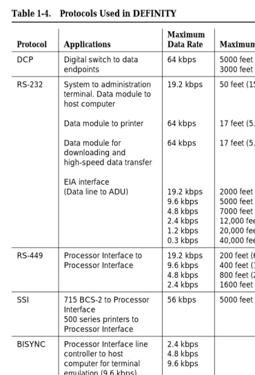
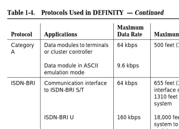
Protocols
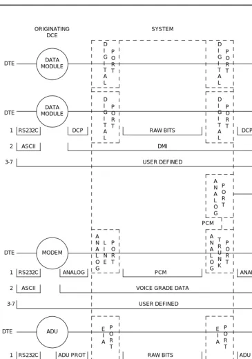
This section describes the protocols handled by the system and the points where these protocols change. Figure 1-1 is a pictorial guide through data-
transmission state changes. Figure 1-1 illustrates the flow of data from DTE equipment, like a terminal or host, through DCE equipment, like a modem or data module, into a communications port on the system. The data flow is shown by solid lines. Below these lines are the protocols used at particular points in the data stream.
Not shown in the Figure 1-1 is the treatment of D-channels in ISDN-PRI and ISDN-BRI transmissions. PRI and BRI D-channels transport information elements
Maintenance Object
Interval (minutes)
POWER 60
SPE-SELEC 60
STBY-SPE 120
TDM-BUS 10
Maintenance for R6vs/si 555-230-127 August 1997 Maintenance Architecture
Page 1-4 Protocols
1
that contain call-signaling and caller information. These elements conform to ISDN level-3 protocol. In the case of BRI, the elements are created by the terminal or data module; for the PRI, the elements are created by the system, which inserts them into the D-channel at the DS1 port.
For ISDN transmissions, therefore, BRI terminals and data modules, and DS1 ports insert, interpret, and strip both layer-2 DCE information and layer-3 elements. Also, the DS1 port passes layer-3 elements to the system for processing.
Layers
The Open System Interconnect (OSI) model for data communications contains seven layers, each with a specific function. Communications to and through the system concern themselves only with layers 1 and 2 of the model.
Layer 1, or the physical layer, covers the physical interface between devices and the rules by which bits are passed. Among the physical layer protocols are RS-232, RS-449, X.21, DCP, DS1, and others.
Layer 2, or the data-link layer, refers to code created and interpreted by the DCE. The originating equipment can send blocks of data with the necessary codes for synchronization, error control, or flow control. With these codes, the destination equipment checks the physical-link reliability, corrects any transmission errors, and maintains the link. When a transmission reaches the destination equipment, it strips any layer-2 information the originating equipment may have inserted. The destination equipment only passes to the destination DTE equipment the information sent by the originating DTE equipment. The originating DTE equipment can also add layer-2 code to be analyzed by the destination DTE equipment. The DCE equipment treats this layer as data and passes it along to the destination DTE equipment as it would any other binary bits.
Maintenance for R6vs/si 555-230-127 August 1997 Maintenance Architecture
Page 1-5 Protocols
1
Figure 1-1. Data Transmission States DCE
ORIGINATING
DCE DESTINATION SYSTEM
RS232C DCP RAW BITS DCP RS232C
1 DTE
2 ASCII DMI ASCII
3-7 USER DEFINED
D I G I T A L P O R T D I G I T A L P O R T D I G I T A L P O R T D I G I T A L P O R T DATA MODULE DATA MODULE DATA MODULE DATA MODULE DTE DTE DATA MODULE DS1 PORT 1 D I G I T A L P O R T RAW BITS
RS232C DCP DS1 FORMAT
DMI ASCII 2 P O R T D S 1 DTE T R U N K P O R T A N A L O G ADU ADU DTE E I A P O R T E I A P O R T DTE DMI
ASYNCH ASCII ASYNCH ASCII
2
3-7 USER DEFINED
RS232C ADU PROT ADU PROT RS232C
1 RAW BITS
3-7 USER DEFINED
VOICE GRADE DATA
ASCII ASCII
2
ANALOG ANALOG
1 RS232C PCM RS232C
P O R T A N A L O G L I N E A N A L O G P O R T DTE DTE MODEM POOLING CABLE MODEM MODEM MODEM PCM
Maintenance for R6vs/si 555-230-127 August 1997 Maintenance Architecture
Page 1-6 Protocols
1
Usage
The following is a list of the protocols when data is transmitted to and through the system. The list is organized by protocol layers. Refer to Figure 1-1.
Layer-1 Protocols
Layer-1 protocols are used between the terminal or host DTE and the DCE, used between the DCE equipment and the system port, and used inside the system.
The following layer-1 protocols are used between the DTE equipment and the DCE equipment. DCE equipment can be data modules, modems, or Data Service Units (DSUs). A DSU is a device that transmits digital data to a particular digital endpoint over the public network without processing the data through any intervening private network switches.
■ RS-232 — A common physical interface used to connect DTE to DCE.
This protocol is typically used for communicating up to 19.2 kbps
■ RS-449 — Designed to overcome the RS-232 distance and speed
restrictions and lack of modem control
■ V.35 — A physical interface used to connect DTE to a DCE. This protocol
is typically used for transmissions at 56 or 64 kbps
The following protocols are used at layer 1 to govern communication between the DCE equipment and the port. These protocols consist of codes inserted at the originating DCE and stripped at the port. The DS1 protocol can be inserted at the originating, outgoing trunk port and stripped at the destination port.
■ Digital Communications Protocol (DCP) — A standard for a 3-channel
link. This protocol sends digitized voice and digital data in frames at 160 kbps. The channel structure consists of two information (I) channels and one signaling (S) channel. Each I-channel provides 64 kbps of voice and/or data communication and the S-channel provides 8 kbps of
signaling communication between the system and DTE equipment. DCP is similar to ISDN-BRI
■ Basic Rate Interface (BRI)
—
An ISDN standard for a 3-channel link,consisting of two 64-kbps bearer (B) channels and one 16-kbps signaling (D) channel. For the implementation of this standard, see DEFINITY Communications System and System 75 and System 85 ISDN BRI Reference, 555-025-103
■ Primary Rate Interface (PRI)
—
An ISDN standard that sends digitizedvoice and digital data in T1 frames at 1.544-Mbps or, for countries outside the United States, in E1 frames at 2.048-Mbps. Layer 1 (physical), layer 2 (link), and layer 3 (network) ISDN PRI protocols are defined in AT&T System 75 and 85 — DS1/DMI/ISDN-PRI — Reference Manual,
Maintenance for R6vs/si 555-230-127 August 1997 Maintenance Architecture
Page 1-7 Protocols
1
The maximum user rate is 64 kbps for voice and data. The maximum distances are based on T1 limitations. At 2.048 Mbps, each E1 frame consists of 32 64-kbps channels
■ Analog
—
A modulated voice-frequency carrier signal■ ADU Proprietary
—
A signal generated by an ADU. The signal is forcommunication over limited distances and can be understood only by a destination ADU or destination system port with a built-in ADU
■ Digital Signal Level 1 (DS1) — A protocol defining the line coding,
signaling, and framing used on a 24-channel line. Many types of trunk protocols (for example, PRI and 24th-channel signaling) use DS1 protocol at layer 1
■ European Conference of Postal and Telecommunications rate 1 (CEPT1)
—
A protocol defining the line coding, signaling, and framing used on a 32-channel line. Countries outside the United States use CEPT1 protocolInside the system, data transmission appears in one of two forms:
1. Raw digital data, where the physical layer protocols, like DCP, are stripped at the incoming port and reinserted at the outgoing port.
2. Pulse Code Modulation (PCM)-encoded analog signals (analog transmission by a modem), the signal having been digitized by an analog-to-digital coder/decoder (CODEC) at the incoming port.
Layer-2 Protocols
Layer-2 protocols are given below:
■ 8-bit character code — Between the DTE equipment and the DCE
equipment. Depending on the type of equipment used, the code can be any proprietary code set.
■ Digital multiplexed interface proprietary
—
Family of protocols betweenthe originating DCE and the destination DCE for digital transmission. See DEFINITY Communications System and System 75 and System 85 DS1/DMI/ISDN PRI Reference, 555-025-101; and Digital Multiplexed Interface [DMI] Technical Specification, 555-025-204
■ Voice-grade data
—
Between the originating DCE and the destinationMaintenance for R6vs/si 555-230-127 August 1997 Maintenance Architecture
Page 1-8 Protocols
1
Protocol States
Table 1-1 summarizes the protocols used at various points in the data transmission stream. See Figure 1-1.
NOTE:
OSI means Open Systems Interconnect PCM means Pulse Code Modulated DMI means Digital Multiplexed Interface
Both the physical-layer protocol and the Digital Multiplexed Interface (DMI) mode used in the connection are dependent upon the type of 8-bit code used at layer 2 between the DTE equipment and DCE equipment, as listed in Table 1-2 and
Table 1-3.
Table 1-1. Protocol States for Data Communication
Transmiss-ion Type
Incoming DTE to
DCE
OSI Layer
Protocols DTE to DCE
DCE to System
Port Inside System
Analog Modem 1 RS-232, RS-449,
or V.35
analog PCM
2 8- or 10-bit code voice-grade data voice-grade data
ADU 1 RS-232 ADU proprietary raw bits
2 asynchronous 8-bit code
asynchronous 8-bit code
DMI
Digital Data
Module
1 RS-232, RS-449, or V.35
DCP or BRI raw bits
2 8-bit code DMI DMI
Digital Signal Level 1 (DS1)
1 any DS1 PCM or raw bits
2 8-bit code DMI or voice-
grade data
DMI or voice- grade data
Table 1-2. Physical-Layer Protocol Versus Character Code
Protocol Code
RS-232 Asynchronous 8-bit ASCII, and synchronous
RS-449 Asynchronous 8-bit ASCII, and synchronous
Maintenance for R6vs/si 555-230-127 August 1997 Maintenance Architecture
Page 1-9 Protocols
1
Connectivity Rules
Figure 1-1 implies the following connectivity rules:
■ Only the DS1 port and the analog trunk port are trunking facilities (all other
ports are line ports). For communication over these facilities, the
destination DCE equipment can be a hemisphere away from the system, and the signal can traverse any number of intervening switching systems before reaching the destination equipment.
■ Data originating at any type of digital device, whether DCP or BRI, can exit
the system at any type of digital port — BRI, digital-line, PRI, DS1, and others; as long as the call destination is equipped with a data module using the same DMI mode used at the call origin. This is because once the data enters the system through a digital port, its representation is uniform (raw bits at layer 1, and DMI at level 2), regardless of where it originated.
■ Although data entering the system through an EIA port has not been
processed through a data module, the port itself has a built-in data module. Inside the system, port data is identical to digital line data. Data entering the system at a DCP line port can exit at an EIA port. Conversely, data entering the system at an EIA port can exit at any DCP line port. The destination data module must be set for Mode-2 DMI communication.
■ Voice-grade data can be carried over a DS1 facility as long as the
destination equipment is a modem compatible with the originating modem
■ If a mismatch exists between the types of signals used by the endpoints in
a connection (for example, the equipment at one end is an analog modem, and the equipment at the other end is a digital data module), a modem-pool member must be inserted in the circuit. When the endpoints are on different switches, it is recommended that the modem-pool member be put on the origination or destination system. A modem-pool Table 1-3. Digital Multiplexed Interface (DMI) Mode Versus
Character Code
DMI Mode Code
0 Synchronous (64 kbps)
1 Synchronous (56 kbps)
2 Asynchronous 8-bit ASCII (up to 19.2 kbps), and
synchronous
Maintenance for R6vs/si 555-230-127 August 1997 Maintenance Architecture
Page 1-10 Protocols
1
member is always inserted automatically for calls to off-premises sites via analog or voice-grade trunking. For internal calls, however, the systems are capable of automatically inserting a modem-pool member.
■ Data cannot be carried over analog facilities unless inside the system it is
represented as a Pulse Code Modulation (PCM)-encoded analog signal. To do this for data originating at a digital terminal, the signal enters the system at a digital port and exits the system at a digital port. The signal then reenters the system through a modem-pool connection (data-module to modem to analog-port) and exits the system again at an analog port.
■ Although DS1 is commonly called a trunk speed, here it names the
protocol used at layer 1 for digital trunks. Some trunks use different signaling methods but use DS1 protocol at layer 1 (for example, PRI and 24th-channel signaling trunks).
Disconnect Supervision
Disconnect supervision means the CO has the ability to release a trunk when the party at the CO disconnects, and the system is abl