Issue 3
January 2001
This document was printed from the Intuity Messaging Solutions Release 5.1 Documentation CD (585-313-803, Issue 3) or the Intuity Messaging Solutions Release 5.1 for Technicians CD (585-313-807, Issue 3). For an electronic version of this information or for additional information, see either
Documentation CD.
was complete and accurate at the time of printing. However, information is subject to change.
Disclaimer
Intellectual property related to this product (including trade-marks) and registered to Lucent Technologies Inc. has been transferred or licensed to Avaya Inc.
Any reference within the text to Lucent Technologies Inc. or Lucent should be interpreted as references to Avaya Inc. The exception is cross references to Avaya Inc. or to books pub-lished prior to April 1, 2001, which may retain their original Lucent tittles.
Avaya Inc. formed as a result of Lucent’s planned restructuring, design builds and delivers voice, converged voice and data, cus-tomer relationship management, messaging, multi-service net-working and structured cabling products and services. Avaya Labs is the research and development arm for the company.
Preventing Toll Fraud
“Toll fraud” is the unauthorized use of your telecommunications system by an unauthorized party (for example, a person who is not a corporate employee, agent, subcontractor, or working on your company’s behalf). Be aware that there may be a risk of toll fraud associated with your system and that, if toll fraud occurs, it can result in substantial additional charges for your telecommu-nications services.
Avaya Inc. Fraud Intervention:
If you suspect that you are being victimized by toll fraud and you need technical assistance or support, call the Technical Service Center’s Toll Fraud Intervention Hotline at 1-800-643-2353.
Providing Telecommunications Security
Telecommunications security (of voice, data, and/or video com-munications) is the prevention of any type of intrusion to (that is, either unauthorized or malicious access to or use of your com-pany’s telecommunications equipment) by some party.
Your company’s “telecommunications equipment” includes both this Avaya product and any other voice/data/video equipment that could be accessed via this Avaya product (that is, “net-worked equipment”).
An “outside party” is anyone who is not a corporate employee, agent, subcontractor, or working on your company’s behalf. Whereas, a “malicious party” is anyone (including someone who may be otherwise authorized) who accesses your telecommuni-cations equipment with either malicious or mischievous intent. Such intrusions may be either to/through synchronous (time-multiplexed and/or circuit-based) or asynchronous (char-acter-, message-, or packet-based) equipment or interfaces for reasons of:
• Utilization (of capabilities special to the accessed equip-ment)
• Theft (such as, of intellectual property, financial assets, or toll-facility access)
• Eavesdropping (privacy invasions to humans)
• Mischief (troubling, but apparently innocuous, tampering) • Harm (such as harmful tampering, data loss or alteration,
regardless of motive or intent)
Be aware that there may be a risk of unauthorized intrusions associated with your system and/or its networked equipment. Also realize that, if such an intrusion should occur, it could result in a variety of losses to your company (including but not limited to, human/data privacy, intellectual property, material assets, financial resources, labor costs, and/or legal costs).
Your Responsibility for Your Company’s Telecommunica-tions Security
The final responsibility for securing both this system and its net-worked equipment rests with you – a Avaya customer’s system administrator, your telecommunications peers, and your manag-ers. Base the fulfillment of your responsibility on acquired knowl-edge and resources from a variety of sources including but not limited to:
• Installation documents
• System administration documents • Security documents
• Hardware-/software-based security tools • Shared information between you and your peers • Telecommunications security experts
• Any other equipment networked to your Avaya products. Avaya Inc. does not warrant that this product or any of its net-worked equipment is either immune from or will prevent either unauthorized or malicious intrusions. Avaya Inc. will not be responsible for any charges, losses, or damages that result from such intrusions.
Federal Communications Commission Statement
Part 15: Class A Statement. This equipment has been tested
and found to comply with the limits for a Class A digital device, pursuant to Part 15 of the FCC Rules. These limits are designed to provide reasonable protection against harmful interference when the equipment is operated in a commercial environment. This equipment generates, uses, and can radiate radio-fre-quency energy and, if not installed and used in accordance with the instruction manual, may cause harmful interference to radio communications. Operation of this equipment in a residential area is likely to cause harmful interference, in which case the user will be required to correct the interference at his/her own expense.
Part 68: Network Registration Number. This equipment is
reg-istered with the FCC in accordance with Part 68 of the FCC Rules. It is identified by FCC registration number
AS593M-13283-MF-E. Refer to “Federal Communications Com-mission Statement” in “About This Book” for more information regarding Part 68.
Canadian Department of Communications (DOC) Interference Information
This digital apparatus does not exceed the Class A limits for radio noise emissions set out in the radio interference regula-tions of the Canadian Department of Communicaregula-tions. Le Présent Appareil Nomérique n’émet pas de bruits radioélec-triques dépassant les limites applicables aux appareils numériques de la class A préscrites dans le reglement sur le brouillage radioélectrique édicté par le ministére des Communi-cations du Canada.
Ordering Information
Call: Avaya Publications Center
Voice 1-800-457-1235 International Voice 317-361-5353
Fax 1-800-457-1764 International Fax 317-361-5355
Write: Avaya Publications Center 2855 North Franklin Road Indianapolis, IN 46219
Order: Document No. 585-310-748 Comcode 108671405 Issue 2, January 2001
For additional documents, refer to the section in "About This Book" entitled "Related Documents."
You can be placed on a standing order list for this and other doc-uments you may need. Standing order will enable you to auto-matically receive updated versions of individual documents or document sets, billed to account information that you provide. For more information on standing orders, or to be put on a list to receive future issues of this document, contact the Avaya Publi-cations Center.
European Union Declaration of Conformity
The "CE" mark affixed to the DEFINITY ONE equipment described in this book indicates that the equipment conforms to the following European Union (EU) Directives:
• Electromagnetic Compatibility (89/336/EEC) • Low Voltage (73/23/EEC)
• Telecommunications Terminal Equipment (TTE) i-CTR3 BRI and i-CTR4 PRI
The “CE” mark affixed to the equipment means that it conforms to the above directives.
For more information on standards compliance, contact your local distributor.
Comments
Contents
Purpose ix
Intended Audiences ix
Release History ix
How to Use This Book x
Conventions Used in This Book x
Terminology x
Keyboard and Telephone Keypad
Representations xiii
Screen Displays xiii
Data Entry Conventions xiv
Safety and Security Alert Labels xv
Trademarks and Service Marks xv
Related Resources xvi
Documentation xvii
Training xvii
Technical Assistance xvii
How to Comment on This Book xviii
1
System 25 Integration Overview 1-1Overview 1-1
Purpose 1-1
Intuity AUDIX Features 1-2
Switch Integration Concepts 1-3
Intuity AUDIX Feature Operation 1-6
INTUITY AUDIX Voice Mail Services 1-6
Call Answer 1-6
Voice Mail 1-6
Automated Attendant 1-7
Bulletin Board Service 1-8
General Call Handling by the
Intuity AUDIX System: Routing Table 1-8
Incoming Called Number 1-9
Business Schedule 1-10
Holiday Schedule(s) 1-11
2
Planning the Integration 2-1Overview 2-1
Purpose 2-1
System 25 Switch Integration Planning 2-2
Completing the Worksheets 2-2
Coverage Options/Maintenance Access
(Worksheet A) 2-3
Voice Messaging Systems
(Worksheet B) 2-5
Floating Personal Dial Code List
(Worksheet C) 2-9
System Dial Plan
(Worksheet D) 2-11
SMDR Parameters for CAS
(Worksheet E) 2-13
Direct Group Calling Groups (DGC Groups)
(Worksheet F) 2-15
Voice Station Records
(Worksheet G) 2-17
Voice Stations – Single Line Generic Example
(Worksheet H) 2-21
Voice Stations – Multiline Generic Example
(Worksheet I) 2-23
Intuity AUDIX System Integration Planning 2-25
Completing the Worksheets 2-25
INTUITY AUDIX System Parameter Features:
Transfer Considerations (Worksheet J) 2-27
Assigning Extension Ranges on the
Intuity AUDIX (Worksheet K) 2-29
Channel Information for Installation
(Worksheet L) 2-31
Assign Services to Called Numbers
(Worksheet M) 2-35
Automated Attendants,
(Worksheets N, O, and P) 2-37
Automated Attendants,
(Worksheets N, O, and P) 2-39
Automated Attendants,
3
Implementing the Integration 3-1Overview 3-1
Purpose 3-1
Perform the Initial Intuity AUDIX System Installation 3-2
Perform the Initial System 25 Administration 3-2
Intuity AUDIX System Initial Administration and Test 3-3
Intuity AUDIX System Initial Administration Checklist 3-4
Perform Acceptance Tests 3-5
Administer/Test Optional Intuity AUDIX Packages 3-6
Test Automated Attendants 3-7
Perform Cut-to-Service Administration 3-7
Test for Validating the Port Connectivity 3-8
Test Busy Extensions 3-8
Test Call No Answer 3-8
Test for Validating Transfers 3-9
Test for Validating Call Disconnection 3-9
Test for Validating MWI Updates 3-9
Test for Validating the Automated Attendant 3-9
Test for Validating the Outcalling Feature 3-10
Test for Validating the Fax Transmission 3-10
Test for Validating MWI Updates 3-10
Test for Viewing the System Monitor 3-11
Perform Networking Administration and Test 3-12
4
Connectivity 4-1Overview 4-1
Purpose 4-1
System 25 Voice Port Requirements 4-2
Intuity AUDIX System Connections 4-3
IVC6 Connections 4-3
Connecting IVC6 Cards Using an 885A Adapter 4-3
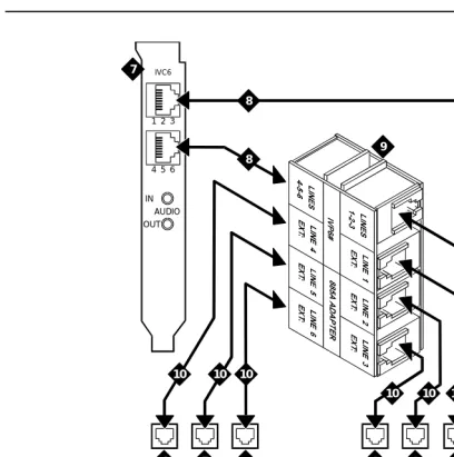
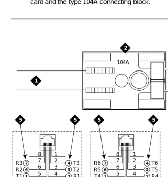
ConnectingIVC6 Cards Using a
104A Connecting Block 4-4
Connecting Serial (COM/tty) Ports 4-6
Connectivity Based on Distance Between
Connecting Serial (COM/tty) Ports Within 50 feet,
Same Power Outlet 4-7
Connecting Serial (COM/tty) Ports More
than 50 Feet, Different Power Outlet 4-10
Connecting CAS via SMDR Ports More Than
50 Feet, Different Power Outlet 4-11
Networking 4-13
Remote Access 4-15
Dedicated Line Access 4-16
Remote Access (Dial) Connections 4-22
5
System 25 Switch Administration 5-1Overview 5-1
Purpose 5-1
Logging in to System 25 5-2
Modifying a User Station to a Consistent Dial Plan 5-4
Modifying Multiple User Extension
Numbers to a Consistent Dial Plan 5-6
Setting Coverage Options 5-7
Administering Tip/Ring Ports for
Use with the INTUITY AUDIX Application 5-8
Assigning Personal Lines to Phantom Extensions 5-10
Send Special Disconnect Code 5-11
Administer CAS Features 5-12
Creating a DGC for the INTUITY AUDIX Application 5-13
Assigning Members to Group Coverage 5-15
Assigning Station Coverage 5-17
Administering Multi-Line Features 5-19
Allowed/Disallowed Lists 5-21
Saving Switch Changes to File 5-22
6
Intuity AUDIX System Administration 6-1Overview 6-1
Purpose 6-2
Administering the Intuity AUDIX
System for Switch Integration 6-2
Intuity AUDIX Main Menu 6-2
Setting the Message Waiting Indicator (MWI)
Device Assignments 6-4
Setting the Dial Plan Translations 6-6
Examples 6-9
Setting MWI Parameters 6-10
Stopping and Starting the Voice System 6-13
Administering the Routing Table 6-15
Access the INTUITY AUDIX Screen 6-16
Entering the Mailboxes for Schedules 6-17
Entering the Business Schedules 6-17
Entering the Holiday Schedules 6-18
Entering the Routing Table 6-20
7
Integration Validation and Troubleshooting 7-1Overview 7-1
Purpose 7-1
Before You Begin 7-2
Integration Validation 7-2
Validating the Tip/Ring Mapping 7-2
Viewing the Switch Integration Logs 7-2
Switch Integration Log Entries 7-6
CHDIP — Raw Data 7-7
SWINDIP — Parsed and Translated Data 7-8
MWIDIP— MWI Updates 7-9
Integration Troubleshooting 7-10
GL
Glossary GL-1About This Book
Purpose
This book, Issue 3, contains the information necessary to integrate an Intuity AUDIX™ system with a System 25 Switch.
Intended Audiences
This book is for the installer who will integrate the Intuity AUDIX system with a System 25 switch.
Secondary audiences include:
■ The project manager who is planning for the installation
■ Remote services personnel.
Release History
How to Use This Book
Installers should use:
■ Chapter 1, ‘‘System 25 Integration Overview’’, to get an overview of the system
■ Chapter 2, ‘‘Planning the Integration’’, to identify information required for the installation
■ Chapter 3, ‘‘Implementing the Integration’’, as an overview of the installation process and as an installation guide
■ Chapter 4, ‘‘Connectivity’’, for connectivity information specific to the System 25 switch
■ Chapter 5, ‘‘System 25 Switch Administration’’, for administering the System 25 switch
■ Chapter 6, ‘‘Intuity AUDIX System Administration’’, for administering the Intuity AUDIX system for the integration
■ Chapter 7, ‘‘Integration Validation and Troubleshooting’’, for integration validation and troubleshooting
Conventions Used in This Book
This section describes the conventions used in this book.
Terminology
■ The word “subscriber” is used in this document when referring to a person administered on the Intuity AUDIX system. Subscriber appears on most of the screens and is the command word you must type at the command line, for example, change subscriber “Jane Doe”.
■ The word “administrator” is used in this document when referring to the system administrator.
■ The word “type” means to press the key or sequence of keys specified. For example, an instruction to type the letter “y” is shown as
Type y to continue.
■ The word “enter” means to type a value and then press . For example, an instruction to type the letter “y” and press is shown as
Enter y to continue.
■ The word “select” means to move the cursor to the desired menu item and then press . For example, an instruction to move the cursor to the Start Test option on the Voice Equipment screen and then press is shown as
Select Start Test.
ENTER
ENTER
ENTER
■ The Intuity AUDIX system displays windows, screens, and menus. Windows show and request system information (Figure 1 and Figure 2, respectively). Screens request that you enter a command at the enter command: prompt (Figure 3). Input is either a value or other specific information you must input through a field (Figure 2) or a command you must enter from the enter command: prompt (Figure 3). Menus (Figure 4) present options from which you can choose to view another menu, or a screen or window.
Figure 1. Example of an Intuity AUDIX Window
Figure 3. Example of an Intuity AUDIX Screen with a Command Line
Keyboard and Telephone Keypad
Representations
■ Keys that you press on your terminal or PC keyboard are represented as rounded boxes. For example, an instruction to press the enter key is shown as
Press .
■ Two keys that you press at the same time on your terminal or PC keyboard (that is, you press and hold down the first key and then press the second key) are represented as a series inside a rounded box. For example, an instruction to press and hold while typing the letter “d” is shown as
Press .
■ A combination keystroke is a series of keystrokes that combines the two key functions described above plus a third key. That is, you press and hold down the first key, then press the second key, then release those keys and press a third key. For example, an instruction to press and hold while typing the letter “d” and then typing the number “1” is shown as
Press .
■ Function keys on your terminal, PC, or system screens, also known as soft
keys, are represented as rounded boxes followed by the function or value
of that key enclosed in parentheses. For example, an instruction to press function key 3 is shown as
Press (Save).
■ Keys that you press on your telephone keypad are represented as square boxes. For example, an instruction to press the first key on your telephone keypad is shown as
Press to record a message.
Screen Displays
■ Values, system messages, field names, and prompts that appear on the screen are shown in typewriter-style Courier type, as shown in the following examples:
Example 1:
Enter the number of ports to be dedicated to outbound traffic in the Maximum Simultaneous Ports: field.
Example 2:
The system displays the message Alarm Form Update was successful.
ENTER
ALT
ALT–D
ALT
ALT–D 1
F3
■ The sequence of menu options that you must select to display a specific screen or submenu is shown as follows:
Start at the Intuity AUDIX main menu and select
:
In this example, you access the main menu and select the line item Customer/Service Administration. From the
Customer/Service Administration menu that the system then displays, you select the line item Alarm Management.
■ Screens shown in this book are examples only. The screens you see on your computer will be similar, but not exactly the same in all cases.
Data Entry Conventions
■ Commands and text you type in or enter appear in bold type, as in the following examples:
Example 1:
Enter change-switch-time-zone at the enter command: prompt.
Example 2:
Type high or low in the Speed: field.
■ Command variables are shown in italic type when they are part of what you must type in, for example:
Enter ch ma machine_name, where machine_name is the name of the call delivery machine you just created.
> Alarm Management
Safety and Security Alert Labels
This book uses the following symbols to call your attention to potential problems that could cause personal injury, damage to equipment, loss of data, service interruptions, or breaches of toll fraud security:
!
CAUTION:
Indicates the presence of a hazard that if not avoided can or will cause minor personal injury or property damage, including loss of data.
!
WARNING:
Indicates the presence of a hazard that if not avoided can cause death or severe personal injury.
!
DANGER:
Indicates the presence of a hazard that if not avoided will cause death or severe personal injury.
!
SECURITY ALERT:
Indicates the presence of a toll fraud security hazard. Toll fraud is the unauthorized use of a telecommunications system by an unauthorized party.
Trademarks and Service Marks
The following trademarked products are mentioned in the books in the Intuity AUDIX library:
■ AT is a trademark of Hayes Microcomputer Products, Inc.
■ AUDIX is a registered trademark of Ayaya, Inc.
■ BT-542B is a trademark of BusLogic Inc.
■ COMSPHERE is a registered trademark of Paradyne Corp.
■ CONVERSANT is a registered trademark of Ayaya, Inc.
■ DEFINITY is a registered trademark of Ayaya, Inc. in the U.S. and throughout the world.
■ Dterm is a trademark of NEC Telephones, Inc.
■ Equinox is a trademark of Equinox Systems, Inc.
■ 5ESS is a registered trademark of Avaya Inc..
■ INTUITY is a trademark of Ayaya, Inc.
■ MEGAPLEX is a trademark of Equinox System, Inc.
■ MEGAPORT is a trademark of Equinox Systems, Inc.
■ Meridian is a trademark of Northern Telecom Limited.
■ MERLIN LEGEND is a registered trademark of Ayaya, Inc.
■ Microcom Networking Protocol is a registered trademark of Microcom, Inc.
■ Microsoft is a registered trademark of Microsoft Corporation.
■ MS is a registered trademark of Microsoft Corporation.
■ MS-DOS is a registered trademark of Microsoft Corporation.
■ NEAX is a trademark of NEC Telephone, Inc.
■ NEC is a registered trademark of NEC Telephones, Inc.
■ Netware is a registered trademark of Novell, Inc.
■ Netware Loadable Module is a trademark of Novell, Inc.
■ NLM is a registered trademark of Novell, Inc.
■ Northern Telecom is a registered trademark of Northern Telecom Limited.
■ Novell is a registered trademark of Novell, Inc.
■ ORACLE is a trademark of Oracle Corporation.
■ Paradyne is a registered trademark of Paradyne Corporation.
■ Phillips is a registered trademark of Phillips Screw Company.
■ Rolm is a registered trademark of International Business Machines.
■ SL-1 is a trademark of Northern Telecom Limited.
■ softFAX is a registered trademark of VOXEM, Inc.
■ TMI is a trademark of Texas Micro Systems, Inc.
■ UNIX is a registered trademark of Novell in the United States and other countries, licensed exclusively through X/Open Company Limited.
■ VOXEM is a registered trademark of VOXEM, Inc.
■ VT100 is a trademark of Digital Equipment Corporation.
■ Windows is a trademark of Microsoft Corporation.
Related Resources
Documentation
The Intuity Messaging Solutions Release 5.1 Documentation contains information about installing the Intuity AUDIX system:
■ Concepts and Features, for general descriptions of the applications available with the Intuity AUDIX system, hardware available, and connectivity
■ Alarms and Events, for alarm and administrative log information
■ Assembling the System (MAP/5P and MAP/5PV3)
■ Assembling the MAP/40P
■ Assembling the Deskside MAP/100P
■ Assembling the Rack-Mounted MAP/100P
Training
The following training class is available for Release 2 Intuity AUDIX Lodging and earlier administration:
■ Course No. BTT506H Ayaya Intuity Messaging Solutions Installation and Maintenance
For more information on Intuity AUDIX training, call the Avaya University and Training Center at one of the following numbers:
■ Organizations within Avaya call: (904) 636-3261
■ Avaya customers call: (800) 255-8988
Technical Assistance
The following resources are available for technical assistance with Avaya products and services:
■ For Avaya technicians only:
Call 1-800-628-8888, and when prompted to do so, enter extension 33715.
■ For customers only:
Call 1-800-242-1212, and when prompted to do so, enter extension 82475.
■ Within Canada:
— For all systems, call 1-800-242-1234.
■ Within any other country:
How to Comment on This Book
We are interested in your suggestions for improving this book. Please complete and return the reader comment card that is located behind the title page.
If the reader comment card has been removed, send your comments to:
Avaya, Inc.
Product Documentation Room D1B53
1300 West 120th Avenue Denver, Co 80234
1
1
System 25 Integration Overview
Overview
This chapter explains how the Intuity AUDIX™ system, the Intuity AUDIX messaging applications, and the System 25 switch work together.
Purpose
Intuity AUDIX Features
The Intuity AUDIX system uses the following messaging packages to provide business- oriented, computerized voice and fax messaging services in support of a telecommunication system:
■ INTUITY AUDIX messaging system
The INTUITY AUDIX voice messaging software application offers the means to record and exchange voice messages with telephone recipients.
The application contains stored voice prompts that guide subscribers in creating, sending, retrieving, answering, saving, or forwarding spoken messages. It also answers calls for subscribers who are busy or unavailable.
The INTUITY AUDIX application can be used as a personal answering service, a messenger to individuals or groups, an information service, an office receptionist, and as an automated attendant service.
■ INTUITY FAX Messaging
The fax messaging application gives the ability to handle faxes using Intuity AUDIX messaging capabilities.
Besides sending, receiving, and printing a fax over the telephone, a subscriber can also forward a fax, annotate a fax with a voice message, send a fax, broadcast a fax to multiple telephone subscribers, and otherwise handle a fax message just as they would a voice message.
Additionally, there are optional software applications that provide expanded or enhanced feature capability for the end user and the system and switch administrators:
— Avaya Communications INTUITY Message Manager 4.5 Message Manager is a software application that runs on a Windows-based PC and connects with the INTUITY AUDIX application through a TCP/IP LAN.
The program uses a graphical interface to enable customers to view a list of their messages on the screen of their PC.
Subscribers can choose messages in any order and, by selecting icons with a mouse, perform all messaging tasks. This is everything that can be done using the telephone keypad.
Message Manager 4.5.6 is the current release. It is compatible with Win98, WinNT, and Windows 2000. Message Manager R4.3 is also available for customers using Win95.
— Intuity AUDIX Call Accounting System
— Intuity AUDIX Lodging
Intuity AUDIX Lodging is a voice mail system designed especially for lodging establishments such as hotels. It supplies guests with electronic mailboxes that store voice messages. Lodging is like having private answering machines that take messages for guests when they are unavailable.
— Internet messaging for INTUITY AUDIX allows subscribers to send and receive voice, fax, text (e-mail), and file attachments to individuals over the internet.
Switch Integration Concepts
Switch integration is the sharing of information between a voice messaging
system and a switch to provide services to callers and subscribers.
A fully integrated messaging system uses information sent from the switch to determine how to process each incoming telephone call.
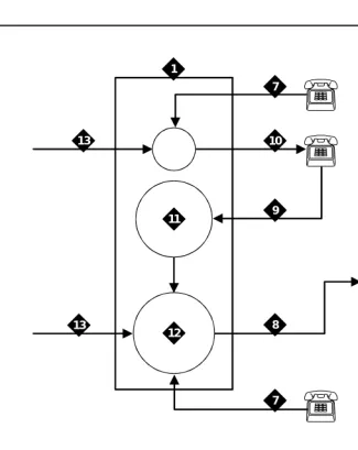
The System 25 switch sends call information by touch-tones over the same voice circuits used for call processing (see Figure 1-1).
Figure 1-1. Call Routing with Switch Integration
cyinovrv RPY 082197
1 2
3
4
5
6 7
7
8 9 10
11
12 13
13
1. System 25 switch
2. Intuity AUDIX system
3. Coverage,#02, local mode code
4. Coverage,#03, outside mode code
5. Direct, #01, outside mode code
6. Direct, #00, local mode code
7. Local call
8. Tip/Ring station line
9. Coverage path
10. Station
11. Coverage group
12. Integrated VMI calling group
The Intuity AUDIX system also interprets switch-hook flashes and call progress tones.
The following information may help you to understand how Intuity AUDIX system applications are integrated with the System 25 switch. More detailed definitions are provided with the System 25 Switch):
■ Coverage path
When a call is not answered because the called station is busy or because the called station did not answer within a specified number of rings, the call is sent to the next point in the coverage path. This may be a secretary, an attendant, etc. The last, or possibly only, coverage point is a calling group that sends calls to the INTUITY AUDIX application.
■ The INTUITY AUDIX calling group
An INTUITY AUDIX calling group has the following characteristics: — When calls arrive, the system searches for an available calling
group member starting with the port after the last port to receive a call. This is called linear hunt.
— Trunks can be set to “ring in” to the calling group so that an incoming trunk call goes directly to the next available port.
— Each member of a calling group is administered as a voice messaging port.
— The calling group can be administered as the receiver for coverage calls so that unanswered calls automatically go to the first available port for coverage.
— An INTUITY AUDIX calling group provides call information to the voice port receiving each call. The call information allows the Intuity AUDIX system to determine if the:
■ Call being processed is a direct call or a coverage call
■ Call is a direct inside call (to the calling group number) or a direct outside call (on any of the trunks assigned to ring into the calling group)
■ Coverage is for one extension calling another, or for a call made from an outside (trunk) to an extension
Coverage for calls is provided by assigning a direct call calling group (or INTUITY
AUDIX calling group) as the last point of each extension’s coverage path.
NOTE:
For complete information on the Intuity AUDIX system, see Avaya INTUITY
Messaging Solutions Release 4, 585-310-235.
Intuity AUDIX Feature Operation
This section describes the operation of the features of most interest for customers integrating a System 25 switch with an Intuity AUDIXsystem.
I
NTUITYAUDIX Voice Mail Services
The INTUITY AUDIX application can be administered to provide the kinds of
services described below.
Call Answer
When callers dial an extension that is busy or does not answer, the INTUITY AUDIX Call Answer feature allows them to leave a message, transfer to another
extension, or transfer to an attendant. System subscribers may record a personal greeting to inform their callers that he or she is unavailable, or select a standard system greeting that callers will hear. Subscribers can record up to nine different greetings for different call types, for example, a call received after business hours or when a subscriber is out of the office.
Subscribers set up a password to protect against unauthorized access to their messages. With this password, messages can be picked up from the office or from an outside telephone.
An optional INTUITY AUDIX feature known as outcalling allows the INTUITY AUDIX application to call a subscriber when a new message arrives. The subscriber can specify the telephone or pager number to be called.
The call is passed from the System 25 switch to the Intuity AUDIX system with call information. This information indicates the covered extension number and whether the call was from an internal station or received on a trunk from outside. Based on this information and on caller actions indicated by pressing touchtone buttons, the Intuity AUDIX system can accept a message for the called
extension’s voice mailbox or provide other special processing.
The system administrator can decide, for security or other reasons, to disable the outcalling feature on a system-wide basis or for selected subscribers.
Voice Mail
left messages. Subscribers can create and edit group lists and send messages to one or more groups. Voice mail services also allow the system manager to send broadcast messages to everyone on the system.
When subscribers receive voice messages in their mailbox, voice mail turns on the message waiting indicator (MWI) on their telephone.
Voice mail can be accessed from internal telephones by dialing the extension for the calling group that contains the Intuity AUDIX system voice ports. From outside, subscribers call in on a trunk that is administered to ring at the Intuity AUDIX system voice port calling group.
Automated Attendant
An automated attendant is an interactive telephone answering system that answers incoming calls with a prerecorded announcement and routes them based on the caller’s response to menus and prompts.
An automated-attendant is set up so that callers hear a menu of options. Callers then press the button on their telephone keypad that corresponds to the menu option they want and the automated-attendant executes the selected option. Callers who do not have touchtone telephones are typically told that they can hold or call another number to speak with a live attendant.
You can design an automated-attendant menu system, or menu tree, to contain subordinate layers of menus or bulletin boards. These sub-menus, or nested
menus, play additional options that can include a choice leading to another nested
menu.
The voiced menu options that callers hear are actually personal greetings that the INTUITY AUDIX system administrator records for the automated-attendant’s extension. The message can be changed as easily as a personal greeting. The Multiple Personal Greetings feature can also be used to provide different menus and options for different types of calls (for example, non-English-language menu options).
The automated-attendant feature can be implemented as a single attendant, that is, as a single extension. A business can also use multiple automated-attendants to handle a variety of call destinations (for example, sales department, accounting department, etc.) and call times (for example, during business hours, during lunch, and after hours).
A phantom multi-button extension has to be created for the automated attendant feature. If you do not want the telephone to ring, and want all calls to be directly transferred to the automated attendant, remove the system-access buttons from the telephone station and give the telephone an automated-attendant class of service.
■ In primary call handling mode, the incoming calls are answered directly by the automated-attendant. A receptionist backs up the automated-attendant by handling overflow calls and calls from people needing assistance (for example, time-outs and dial 0).
■ In secondary call handling mode, a receptionist answers as many calls as possible and the automated-attendant handles any overflow calls.
Bulletin Board Service
Bulletin Board service (also called Information service) is a mailbox used as a call-in information facility. The caller hears a prerecorded, informational message and is then disconnected. As with an automated-attendant, the informational message is the personal greeting that the INTUITY AUDIX system administrator records for the bulletin board’s extension. The message can be changed as easily as a personal greeting.
The call is passed from the System 25 switch to the Intuity AUDIX system with call information. This information allows the Intuity AUDIX system to provide
information service processing based on the covered extension on which the call is received.
Alternately, Bulletin Board service can provide multiple messages by using a menu within an automated-attendant.
General Call Handling by the
Intuity AUDIX System: Routing Table
Calls for the INTUITY AUDIX application are processed through DNIS_SVC. The INTUITY AUDIX application then processes the call based on the called number as follows. If the called number is defined as a(n):
■ Regular voice mailbox, call answer service is provided.
■ Bulletin Board extension, bulletin board service is provided.
■ Auto-attendant mailbox, automated-attendant service is provided.
To expand upon the possibilities for incoming calls, a special table is used. The following discussion describes the process illustrated in Figure 1-2.
■ Routing Table
The routing table is provided to:
— Specify automated-attendant menus for calls on trunks or specified covered extensions
— specify different call handling by automated-attendants based on a business, holiday, or alternate service schedule
The routing table can have up to 25 entries. Each entry has the following columns:
■ Incoming Called Number (or range)
■ Business Schedule
■ Holiday Schedule
■ Alternate Service Mailbox
Incoming Called Number
Each incoming call is matched to the Incoming Called Number column in the routing table. The called number is either the telephone extension of the covered extension number of the automated-attendant, a direct trunk (999). The called number is analyzed as follows:
1. If an incoming call is to one of the numbers in the table, further examination is made of the Business Schedule and Holiday Schedule columns.
Otherwise, the call is passed directly to the INTUITY AUDIX application. 2. If the specific tag login is found in the Business Schedule column, the call
receives INTUITY AUDIX login service.
3. The current date is matched against the Date column of the holiday schedule, if any, specified in the Holiday Schedule column of the routing table. If the date matches a holiday, the automated-attendant extension specified in the Mailbox column of the holiday schedule is substituted for the original called number. The call is then passed to the INTUITY AUDIX application.
NOTE:
The substitution is from the holiday schedule.
4. If a holiday match is not found, the current time is matched against the Alternate Service Hours columns for the current day of the week in the business schedule, if any, specified in the Business Schedule column of the routing table. If the current time is within the specified range, the automated-attendant extension specified in the Alternate Service Mailbox column of the routing table is substituted for the original called number. The call is then passed to the INTUITY AUDIX application.
NOTE:
5. Finally, if the current time is during the day service hours, if any, specified in the Business Schedule column of the routing table, the
automated-attendant extension specified in the Day Service Mailbox column of the routing table is substituted for the original called number. The call is then passed to the INTUITY AUDIX application.
NOTE:
The substitution is based on the business schedule, but it is from the routing table, and not from the business schedule.
Business Schedule
A maximum of four business schedules can be defined. The name or number of one of these business schedules is placed in the Business Schedule column of the routing table. This associates the particular business schedule with a called number or range specified in the Incoming Called Number column of the routing table.
Each business schedule has the following fields and columns:
■ Business Schedule (name)
■ Day of Week
■ Day Service Hours Start
■ Day Service Hours End
■ Alternate Service Hours Start
■ Alternate Service Hours End
NOTE:
These fields and columns are used for matching only. The automated -attendant extensions associated with a match are taken from the routing table.
The Business Schedule name is arbitrary and can be changed to indicate the use of the specific schedule. It can contain up to eight letters or digits. The default names are “bus1” through “bus4”.
The Day of Week column is fixed. To specify night service 24 hours a day, leave the start and end times blank. To specify day service 24 hours a day, use 00:00 as the start time and 23:59 as the end time.
The Alternate Service Hours feature allows the automated-attendant to play a different menu or handle calls slightly differently during lunch time and to
Holiday Schedule(s)
A maximum of four holiday schedules can be defined. Each holiday schedule can have up to 26 entries. The name or number of one of these holiday schedules is placed in the Holiday Schedule column of the routing table. This associates the particular holiday schedule with a called number or range specified in the Incoming Called Number column of the routing table.
Each holiday schedule has the following fields and columns:
■ Holiday Schedule (name)
■ Holiday Name
■ Date
■ Mailbox
NOTE:
The Date column is used for matching. The automated-attendant extension associated with a match is taken from the Mailbox column of this same table. The Holiday Name column is for documentation only.
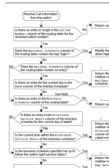
Figure 1-2. Call-processing Flow Chart
AUDIX
Note: The Business Schedule and
Holiday Schedule columns of the routing table cannot both be blank.
Return the automated attendant mailbox number specified in the
Day Service Mailbox column of the routing table as the called number
No
Yes
Does the Business Schedule column of the routing table contain the tag "login"? Is there an entry or range in the Called Number column of the routing table for the received called number?
Yes Modify the Call Type to provide direct login to Voice Mail
Does the Holiday Schedule column of the routing table contain an entry?
Is there an entry for the current day in the
Date column of the Holiday Schedule?
Yes No
Return called number as received
AUDIX
AUDIX No
Yes Return the automated attendant mailbox number specified in the
Mailbox column of the holiday schedule as the called number
AUDIX No
Is there an entry in the Business Schedule column of the routing table?
Return called number as received
AUDIX No
Yes
Is there an entry in the Alternate Service Hours column of the business schedule for the current day of week?
Return the automated attendant mailbox number specified in the
Alternate Service Mailbox
column of the routing table as the called number
AUDIX Yes
Yes
Is the current time within the Alternate Service Hours of the business schedule?
Yes No
No
Is the business schedule specified set up to follow the switch night service status?
Return the automated attendant mailbox number specified in the
Day Service Mailbox or
Night Service Mailbox
column of the routing table depending on the switch night service status as the called number
AUDIX Yes
No
Is the current time in the day service range? No
Return the automated attendant mailbox number specified in the
Night Service Mailbox
column of the routing table as the called number
AUDIX Yes
See Note Receive Call Information
from the switch
P
P
P
P
Functionality Differences for the
System 25 Switch
The process of integrating the Intuity AUDIX system with the System 25 switch differs from integrations with other switches in the following ways:
■ The System 25 switch does not differentiate between busy and no answer. Therefore, it is not possible to play different greetings based on whether the person is out of their office or just on another call.
■ High-speed digital networking is not supported.
■ DCS networking is not supported.
2
2
Planning the Integration
Overview
Before you integrate the Avaya System 25 switch with the Intuity AUDIX™ system, you must plan the process. This chapter provides information about the information needed to integrate the two systems, including the settings on the System 25 switch and the settings on the Intuity AUDIX system.
Purpose
System 25 Switch Integration Planning
To plan for the System 25 switch side of the integration, complete the following worksheets:
■ Worksheet A: Coverage Options/Maintenance Access
■ Worksheet B: Voice Messaging Systems
■ Worksheet C: Floating Personal Dial Code List
■ Worksheet D: System Dial Plan
■ Worksheet E: SMDR Parameters for CAS
■ Worksheet F: DGC Groups
■ Worksheet G: Voice Station Records
■ Worksheet H: Voice Stations – Single Line Generic Example
■ Worksheet I: Voice Stations – Multiline Generic Example
!
CAUTION:
Planning and administering toll restrictions options, such as Automatic Route Selection (ARS) and allowed/disallowed lists, is beyond the scope of this document. However, to successfully integrate the System 25 switch with the Intuity AUDIX system, these items must be addressed.
Completing the Worksheets
Coverage Options/Maintenance Access
(Worksheet
A
)
Write in a number that is compatible with your business needs.Normally, three or four rings are allowed before a call is sent to coverage.
NOTE:
Coverage is set on a system-wide basis. This affects station coverage and automated-attendants.
Typically, coverage ringing on internal calls should be left at its default setting of Yes.
Worksheet A:
Coverage
Options/Maintenance Access
Customer:
Prepared by:
Telephone Number:
Date:
Intuity AUDIX Location/Name:
DEFAULT MODIFY
Allow coverage ringing on internal calls (scroll)? Yes
Number of rings before calls are sent to coverage (0 – 31): 2
Voice Messaging Systems
(Worksheet
B
)
Voice ports used for communication between the System 25 switch and the Intuity AUDIX system must be assigned on a Tip/Ring or Analog Line Module (ZTN78, TN742, or TN746B). Write the Carrier/Slot/Port and the PDC in the appropriate columns.
The VMS port is typically dial accessible. Write Yes in the Make VMS Port Dial Accessible? column. Dial accessibility allows the technician to dial a specific port and is useful for testing.
Write No in the Make Port an Extended Station? column.
Typically, the display ID is AUDIX and a port number. Write this in the Display ID column.
Typically, outward toll calls are restricted and you would write Yes in the Toll Outward Call Restriction column. However, if your site has outcalling, AMIS Analog networking, or fax messaging, write No in the appropriate row.
The toll restriction class depends on how ARS is implemented at your site. Write the applicable class in the Toll Restriction Class column.
Write the ARS facility restriction level in the far right column.
!
CAUTION:
Me ssa ging Solut ions Rele ase 5.1 ion w ith Syst em 2 5 Is su e 3 J a n uar y 2 001 Inte gra tion Page 2-6 2 5 Sw itch Int egra tio n Pl ann ing
e
t B:
V
o
ice M
e
ss
a
g
in
g
e
m
s
C/SS/PP PDC Board
Me ssa ging Solut ions Rele ase 5.1 ion w ith Syst em 2 5 Is su e 3 J a n uar y 2 001 Inte gra tion Page 2-7 2 5 Sw itch Int egra tio n Pl ann ing V o ic e Messa g ing Sy st em – Co nt inu ed .
Accessible? Station? ID Call Restrict Class Level
Floating Personal Dial Code List
(Worksheet
C
)
Floating Personal Dial Codes (FPDCs) are used primarily to implement
automated attendants on systems that have DID trunks. If you do not plan to use automated-attendants, skip the Floating Personal Dial Code List worksheet.
FPDCs are virtual extensions that can be logged into any station set. FPDCs can be assigned to DID numbers but cannot terminate trunks. An FPDC does not have its own coverage; it follows that of the station to which the FPDC is logged on.
To use FPDCs with the INTUITY AUDIX application effectively, the FPDC must be logged onto an unused host extension that covers to the INTUITY AUDIX
Worksheet C:
Floating Personal
Dial Code List
Customer: _______________________________________________________
Prepared by: _____________________________________________________
Phone Number: ___________________________________________________
Date: ___________________________________________________________
Intuity AUDIX Location/Name: ______________________________________
:
NOTE:
If DID trunks are used, we recommend that the PDCs be less than or equal to the number of digits sent by the central office.
System Dial Plan
(Worksheet
D
)
Fill out the worksheet according to your System 25 switch parameters, using the following integration-specific discussion.
Worksheet D:
System Dial Plan
Customer: __________________________________________________
Prepared by: ________________________________________________
Phone Number: ______________________________________________
Date: ______________________________________________________
Intuity AUDIX Location/Name: _________________________________
PDCs used to access parked calls (1–9999 or 0 for “None”)
Table 2-1. System Dial Plan
DEFAULT MODIFY
ARS access code (1–9999 or 0 for “None”): 9
Central office trunk pool access code (0–9999): 100
Night service access code (0–9999):
Modem request code (1–9999 or 0 for “None”):
Number of DID digits used by PDCs (scroll): 3
Disallow busy of ground start trunks (scroll): No
Allow incoming LS trunks transferred out (scroll): No
Name for attendant: Attendant
Name for DID trunks: Outside
Name for no DID trunks: No DID in
Dial tone for incoming tie trunks (scroll): Yes
Return time (seconds) for parked calls (0–240) 120
Send special disconnect code ##99 to VMS port (scroll) Yes No
DEFAULT: 1:800 2:801 3:802 4:803 5:804 6:805 7:806 8:807
SMDR Parameters for CAS
(Worksheet
E
)
Call Accounting System (CAS) is an optional application. If your configuration includes CAS, fill out the worksheet according to your System 25 parameters. If your site does not have CAS, skip this worksheet.
Intuity AUDIX serial ports need a multi-port serial card.
To ensure that the System 25 switch collects the required call information and formats it in a manner that CAS can use:
Write yes to send SMDR records to the SMDR port
Write 10 as the minimum number of seconds the call must last before
incrementing the peg count. This setting allows the System 25 switch to reject calls to busy numbers or calls resulting from a misdialed number.
Worksheet E:
SMDR Parameters
for CAS
Customer: __________________________________________________
Prepared by: ________________________________________________
Phone Number: ______________________________________________
Date: ______________________________________________________
Intuity AUDIX Location/Name: _________________________________
DEFAULT MODIFY
Allow SMDR records to be sent to SMDR port (scroll)? Yes Yes
Minimum duration of call (in seconds) before recording: 40 15
Number of digits used for account codes (1–15): 15
Direct Group Calling Groups (
DGC Groups
)
(Worksheet
F
)
Fill out the worksheets according to your System 25 parameters, using the following integration-specific discussion.
You must have at least one calling group and possibly several calling groups that contain the voice ports that connect the System 25 switch to the Intuity AUDIX system. To define each calling group, assign available numbers.
Typically, DGC group 10 is used for the INTUITY AUDIX calling group. Write the number for the calling group in the Group # field. (If using DGC group 10, 110 would be the group coverage number for extensions covered by the INTUITY
AUDIX application.)
The AUDIX Access # should be defined by the INTUITY AUDIX system administrator.
Typically, the Name of this DGC group is AUDIX.
Worksheet F:
DGC Groups
Customer: __________________________________________________
Prepared by: ________________________________________________
Phone Number: ______________________________________________
Date: ______________________________________________________
Intuity AUDIX Location/Name: _________________________________
Group # Access # Name Location Disable Q Msg
Waiting
(Use what has been defined on the Voice Messaging Systems worksheet.)
GROUP MEMBER S
Voice Station Records
(Worksheet
G
)
NOTE:
The Voice Station Records worksheet has been customized to facilitate the integration of a System 25 switch with an Intuity AUDIX system.
Fill out the worksheet according to your System 25 parameters, using the following integration-specific discussion.
PDCs must be three or four digits, but not both. Write this in the PDC/DDC column.
If this station is to be covered by the INTUITY AUDIX application, write Yes in the Covered by AUDIX? column.
NOTE:
Worksheet G:
Voice Station Records
Customer: __________________________________________________
Prepared by: ________________________________________________
Phone Number: ______________________________________________
Date: ______________________________________________________
Intuity AUDIX Location/Name: _________________________________
Employee Name
Terminal Location
Terminal Type
PCD/ DDC
Port Assigned1
Jack Number 2
SIP Number1
Covered by AUDIX?
(Sheet 1 of 2) NOTE: Write the
telephone extension of the remote
1.From System 25 Installer 2.From Wiring Installer
Voice Stations – Single Line Generic Example
(Worksheet
H
)
Fill out the worksheet according to your System 25 parameters, using the following integration-specific discussion.
Write:
■ 100 + the DGC group number for the INTUITY AUDIX application (typically 10) for the group coverage number
■ Yes to allow call coverage ring on no answer
Worksheet H:
Voice Stations –
Single Line Generic Example
Customer: __________________________________________________
Prepared by: ________________________________________________
Phone Number: ______________________________________________
Date: ______________________________________________________
Intuity AUDIX Location/Name: _________________________________
PDC (1-9999) PORT # (1-3/1-12/1-8): / /
NAME (LAST, FIRST) LOC
TYPE (scroll): SINGLE LINE
BUTTONS CLASS OF SERVICE
Class of Service: _________________ DEFAULT MODIFY
Group coverage number (1-32, 101-132, 0 for “None”) 1 110 Allow call coverage ring on no answer (scroll)? Yes Yes Allow call coverage ring on busy (scroll)? Yes No Extended, out-of-building for off-promises station (scroll) No
PDC to hunt to next (1-9999, 0 for “None”) 0 DDCs that can dial for this station (RETURN key)
Call Waiting (scroll)? No
F7 (NEXT)
Restrict access to CO trunk pool (scroll)? No Restrict access to all other trunk pools (scroll)? No Force account code entry administration (scroll)? 0
Number of internal retries (0-15) 2
Number of rings per try for internal calls (2-15) 3
Number of outgoing retries (0-15) 2
Number of rings per try for outgoing calls (2-15) 3 Automatic queueing for internal call (scroll)? No Automatic queueing for outgoing call (scroll)? Yes Member of call pickup group number (1-16, 0 for none) 0 Total outward call restriction (scroll) No
Toll restriction class (scroll) None
Voice Stations – Multiline Generic Example
(Worksheet
I
)
One generic multiline worksheet is included with this book. If your site has more than one type of multiline set, make copies of this worksheet and fill out as required.
Fill out the worksheets according to your System 25 parameters, using the following integration-specific discussion.
Write:
■ 100 + the DGC Group Number for the INTUITY AUDIX application (typically 10) for the Group Coverage Number
■ Yes to allow call coverage ring on no answer
Worksheet I:
Voice Stations –
Multiline Generic Example
Customer: __________________________________________________
Prepared by: ________________________________________________
Phone Number: ______________________________________________
Date: ______________________________________________________
Intuity AUDIX Location/Name: _________________________________
PDC (1-9999) PORT # (1-3/1-12/1-8): / /
NAME (LAST, FIRST) LOC
TYPE (scroll): MULTI LINE
BUTTONS CLASS OF SERVICE
Class of Service: _________________ DEFAULT MODIFY
Group coverage number (1-32, 101-132, 0 for “None”) 1 110 Allow call coverage ring on no answer (scroll)? Yes Yes Allow call coverage ring on busy (scroll)? Yes No Extended, out-of-building for off-promises station (scroll) No
PDC to hunt to next (1-9999, 0 for “None”) 0 DDCs that can dial for this station (RETURN key)
Call Waiting (scroll)? No
F7 (NEXT)
Restrict access to CO trunk pool (scroll)? No Restrict access to all other trunk pools (scroll)? No Force account code entry administration (scroll)? 0
Number of internal retries (0-15) 2
Number of rings per try for internal calls (2-15) 3
Number of outgoing retries (0-15) 2
Number of rings per try for outgoing calls (2-15) 3 Automatic queueing for internal call (scroll)? No Automatic queueing for outgoing call (scroll)? Yes Member of call pickup group number (1-16, 0 for none) 0 Total outward call restriction (scroll) No
Toll restriction class (scroll) None
Intuity AUDIX System Integration
Planning
To plan for the Intuity AUDIX system side of the integration, complete the following Intuity AUDIX system planning worksheets:
■ Worksheet J: INTUITY AUDIX System Parameter Features: Transfer Considerations
■ Worksheet K: Assigning Extension Ranges on the Intuity AUDIX
■ Worksheet L: Channel Information for Installation
■ Worksheet M: Assign Services to Called Numbers
NOTE:
Worksheet L: Channel Information for Installation and Worksheet M:
Services for Assign Services to Called Number are numbered in the
order that the information must be entered into the Intuity AUDIX system. They are discussed in reverse order because it makes the explanation easier.
The remaining three worksheets deal with planning for automated-attendants on systems that have DID trunks.
If you do not plan to use auto-attendants, skip the following worksheets:
■ Worksheet N: Business Schedule
■ Worksheet O: Holiday Schedule
■ Worksheet P: Routing Table
Completing the Worksheets
I
NTUITYAUDIX System Parameter Features:
Transfer Considerations (Worksheet
J
)
The Intuity AUDIX system features required for the System 25 switch are recorded on Worksheet J. The following parameters should be set:
■ Digits in Dial Plan – The Intuity AUDIX system requires a fixed length dial plan. You can use either a three-digit or four-digit dial plan, but not both.
■ Transfer Type = basic
■ Transfer Restriction = subscribers
Worksheet J:
I
NTUITY
AUDIX System
Parameter
Features: Transfer Considerations
Customer: __________________________________________________
Prepared by: ________________________________________________
Phone Number: ______________________________________________
Date: ______________________________________________________
Intuity AUDIX Location/Name: _________________________________
Parameter Valid Values Installer’s Entry
Number of digits in dial plan
3 or 4
(This value is entered in the extension length field on the
Switch Interface
Administration screen)
Transfer considerations:
Transfer type none, basic,
enhanced_no_cover_0, enhanced_0
basic
Transfer restriction subscribers, digits subscribers
Covering extension system console or
operator extension Announcement sets:
System Administration
Rescheduling increments: Days Hours Minutes Days Hours Minutes
Increment 1 Default 0 Default 0 Default 5
Increment 2 Default 0 Default 0 Default
15
Increment 3 Default 0 Default 0 Default
30
Increment 4 Default 0 Default 1 Default 0
Increment 5 Default 0 Default 2 Default 0
Increment 6 Default 0 Default 6 Default 0
Increment 7 Default 0 Default 6 Default 0
Increment 8 Default 0 Default 6 Default 0
Increment 9 Default 0 Default 6 Default 0
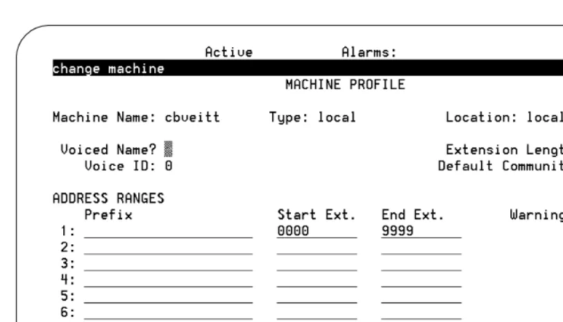
Assigning Extension Ranges on the
Intuity AUDIX
(Worksheet
K
)
You will have to administer the extension ranges on the Intuity AUDIX that are valid extensions for your site. Use the following guidelines when filling out Worksheet K.
■ Prefix
Prefixes can be used on the local machine, but they limit the functionality and are not recommended.
■ Starting extension
These are the starting extensions for the ranges of telephone numbers used on the local system (a block of switch extensions that can be used at the local system when assigning subscribers). For example, if your system uses extensions between 2000 and 3000, enter 2000 in the Starting Extension field.
Up to 10 different ranges can be specified to pinpoint the exact set of extension blocks used by the local system. The length of the starting and ending extension must agree with the Extension Length field.
■ Ending extension
Worksheet K:
Assigning Extension
Ranges on the Intuity AUDIX
Customer: __________________________________________________
Prepared by: ________________________________________________
Phone Number: ______________________________________________
Date: ______________________________________________________
Intuity AUDIX Location/Name: _________________________________
Digits in Dial Plan
Address Ranges Notes
Prefix Starting Extension Ending Extension
1.
2.
3.
4.
5.
6.
7.
8.
9.
Channel Information for Installation
(Worksheet
L
)
For Intuity AUDIX to operate properly, it must know what extension has been assigned to each of its channels (voice ports) and how incoming calls on that channel are to be processed. Worksheet L provides columns for Channel Number, Extension, Initial Service, and Optional Dedicated Service.
For each channel, you must fill in the extension number. All channels that are part of an INTUITY AUDIX calling group should be assigned DNIS_SVC.
Worksheet L:
Channel Information
for Installation
Customer: __________________________________________________
Prepared by: ________________________________________________
Phone Number: ______________________________________________
Date: ______________________________________________________
Intuity AUDIX Location/Name: _________________________________
Use this worksheet to assign the extension numbers to the channel. The initial service will be *DNIS_SVC.
Channel
Number Extension Initial Service
Optional Dedicated Service
1 *DNIS_SVC
2 *DNIS_SVC
3 *DNIS_SVC
4 *DNIS_SVC
5 *DNIS_SVC
6 *DNIS_SVC
7 *DNIS_SVC
8 *DNIS_SVC
9 *DNIS_SVC
10 *DNIS_SVC
11 *DNIS_SVC
12 *DNIS_SVC
13 *DNIS_SVC
14 *DNIS_SVC
15 *DNIS_SVC
16 *DNIS_SVC
17 *DNIS_SVC
18 *DNIS_SVC
19 *DNIS_SVC
Channel
Number Extension Initial Service
Assign Services to Called Numbers
(Worksheet
M
)
All calls not assigned to a specific INTUITY IVR (Introactive Voice Response) application directly are processed by the *DNIS_SVC. In order for *DNIS_SVC to function with both INTUITY AUDIX and INTUITY IVR applications defined in a shared port group, the installer must fill out a table in the system that tells the DNIS_SVC which called number should receive a particular service.
Worksheet M provides a Service Name column and a Called Number column. The worksheet should contain an initial entry with AUDIX in the Service Name column and ANY in the Called Number column.
Worksheet M:
Assign Services to
Called Numbers
Customer: __________________________________________________
Prepared by: ________________________________________________
Phone Number: ______________________________________________
Date: ______________________________________________________
Intuity AUDIX Location/Name: _________________________________
Instructions
:The service name is either AUDIX, AUDIX+Ldgn (if Lodging is installed), or a unique INTUITY
Introactive Voice Response application name. The IVR application names are for planning purposes only. They may not be assigned as a service until after the IVR application is loaded onto the system.
The called number is either the word ANY or the specific extension number that has been assigned to support a particular service.
Field Service Name Called Number
1 AUDIX ANY
Automated Attendants,
(Worksheets N, O, and P)
An automated attendant is an interactive telephone answering system that answers incoming calls with a prerecorded announcement and routes them based on the caller’s response to menus and prompts.
An automated-attendant is set up so that callers hear a menu of options. Callers then press the button on their telephone keypad that corresponds to the menu option they want and the automated-attendant executes the selected option. Callers who do not have touchtone telephones are typically told that they can hold or call another number to speak with a live attendant.
If your configuration does not include automated-attendants, skip Worksheets N,
<