System 75
Console Operation
Addendum 1, Dated
November 1990 for
555-200-700
Issue 5, June 1990
Write: AT&T Customer Information Center 2855 North Franklin Road
P.O. Box 19901
Indianapolis, IN 46219-1385
While reasonable efforts were made to ensure that the information in this document was complete and accurate at the time of printing, AT&T can assume no responsibility for errors. Changes or corrections to the information in this document may be incorporated into future reissues.
Published by
The AT&T Documentation Development Organization
Attendant Console Selector Console Functional Areas
Attendant Console Tones
CHAPTER 3. OPERATING THE CONSOLE
Activating and Deactivating the Console Answering Calls Placing Calls Releasing Calls Holding Calls Splitting Calls Extending CallsCHAPTER 4. USING THE FEATURES
Abbreviated Dialing (V2, V3, and Generic 1 Systems) Attendant Auto-Manual Splitting
Attendant Call Waiting Attendant Conference
Attendant Control of Trunk Group Access Attendant Direct Trunk Group Selection Attendant Lockout
Attendant Recall
Automatic Alternate Routing (V2, V3, and Generic 1 Systems) and Automatic Route Selection
Automatic Circuit Assurance (V2, V3, and Generic 1 Systems)
Busy Verification of Terminals and Trunks (V2, V3, and Generic 1 Systems) Call Coverage
-i-Facility Test Call 4-19 Individual Attendant Access (V2, V3, and Generic 1 Systems) 4-19
Integrated Director 4-20
Integrated Services Digital Network (lSDN)—Primary Rate Interface (PRI)
(Generic) 4-23
Inter-PBX Attendant Calls (V2, V3, and Generic 1 Systems) 4-26
Leave Word Calling 4-28
Loudspeaker Paging Access (V1, V2, V3, and Generic 1 Systems) 4-29 Loudspeaker Paging Access—Deluxe (Generic 1 Only) 4-31
Message Retrieval 4-34
Multiple Listed Directory Numbers 4-36
Network Access-Private 4-36
Network Access—Public Night Service
SMDR Account Code Dialing Straightforward Outward Completion Time-of-Day Routing (Generic 1 Only) Timed Reminder
Through Dialing
Trunk Group Busy/Warning Indicators to Attendant
4-36 4-36 4-37 4-38 4-38 4-41 4-42 4-42 Trunk Identification (V2, V3, and Generic 1 Systems) 4-42 Trunk-to-Trunk Transfer 4-43
CHAPTER 5. USING THE DCS FEATURES (V2, V3, AND GENERIC 1
SYSTEMS)
DCS Attendant Call Waiting 5 - 1
DCS Attendant Control of Trunk Group Access 5 - 1
DCS Attendant Display 5 - 1
CHAPTER 6. CENTRALIZED ATTENDANT SERVICE (CAS) (V3 AND
GENERIC 1 SYSTEMS)
Description
Tones Associated With CAS Calls Display
Operating Procedures CAS Backup Service
CAS Night Service Operations
CHAPTER 7. ROUTINE MAINTENANCE
TestingCare and Cleaning Power Failure
CHAPTER 8. USING THE CONSOLE TO TROUBLESHOOT THE
SYSTEM
Trouble Reporting
Console Alarm Indicators
Features Used in Troubleshooting Other Maintenance Tips
CHAPTER 9. SYSTEM SUMMARY
List of Dial CodesSystem and Console Parameters
CHAPTER 10. REFERENCES
CHAPTER 11. GLOSSARY
CHAPTER 12. INDEX
6-1 6-1 6-2 6-3 6-4 6-7 6-8 7-1 7-1 7-1 7-2 8-1 8-1 8-1 8-2 8-9 9-1 9-1 9-4 10-1 11-1 12-1
-Figure 2-4.
Figure 2-5.
Figure 2-6.
Figure 2-7.
Figure 2-6.
Figure 2-9.
Figure 2-10.
Figure 2-11.
Figure 2-12.
Figure 2-13.
Figure 2-14.
T a b l e 2 - A .
Enhanced Selector Console (27AI-A-03)
Trunk Group Select Buttons and Lamps, Basic Console
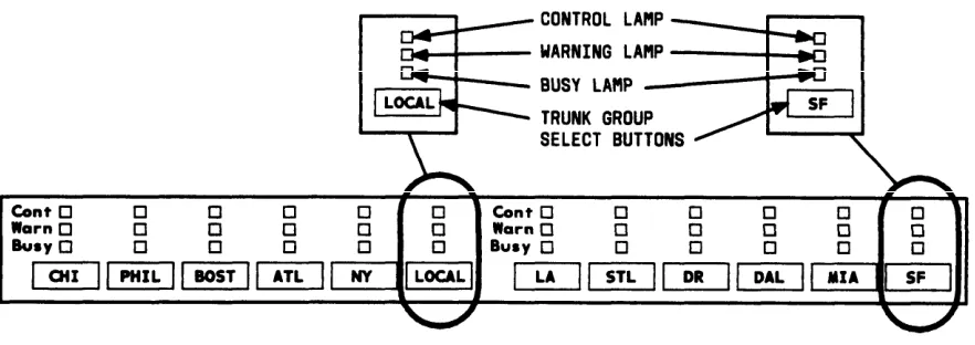
Trunk Group Select Buttons and Lamps, Enhanced Console
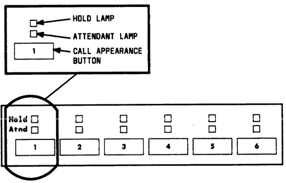
Call Appearance Buttons and Lamps
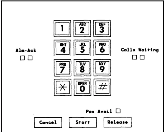
Call Processing Area, Basic Console
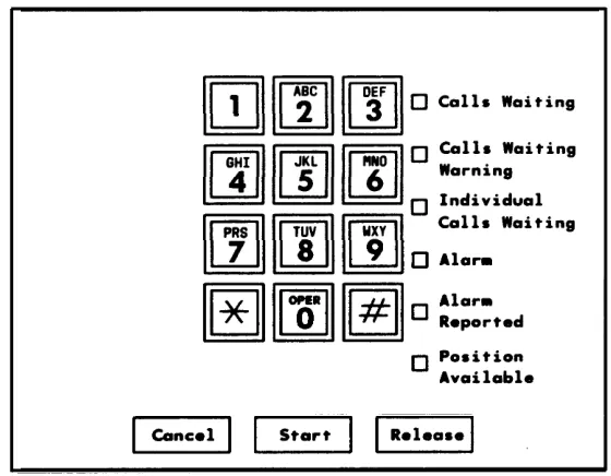
Call Processing Area, Enhanced Console
Fixed Feature Buttons
Alphanumeric Display, Basic Console
Alphanumeric Display, Enhanced Console
Basic Selector Console Area
Enhanced Selector Console Area
2-4
2-5
2 6
2-8
2-9
2-10
2-14
2-21
2-21
2-31
2-32
Tables
CHAPTER 1. INTRODUCTION
This guide to the operations of the system attendant console is for use by console attendants after training is completed. It provides detailed step-by-step instructions for each operation accompanied by descriptions of the possible system responses.
Note: This guide does not cover operations associated with Hospitality Services and Automatic Call Distribution (ACD). Information on these groups of features can be found in the following documents:
• DEFINITY® Communications System Generic 1 and System 75— Hospitality Operations, 555-200-723
• AT&T System 75—Automatic Call Distribution (ACD)—Agent Instructions, 555-200-722
• AT&T System 75—Automatic Call Distribution (ACD)—Supervisor Instructions, 555-200-724.
This issue replaces all previous issues of this document. Reasons for reissue include the f o l l o w i n g :
• To include information on enhanced DEFINITY Communications System Generic 1 • To include information on an additional attendant console model called the enhanced
attendant console
• To include information on an additional selector console model called the enhanced selector console
• To include the Loudspeaker Paging Access—Deluxe feature
• To include information on hundreds group numbers for systems that handle more than 800 lines
• To clarify some existing information to make the guide easier to use.
This guide contains terms that specifically apply to the system attendant console; they are defined in the text where they are first used and are also entered in the Glossary. Terms associated with communications systems in general are listed and defined in the Glossary.
The information contained in this guide applies to:
• DEFINITY Communications System Generic 1 • System 75 (Version 1, Version 2, and Version • System 75 XE (Version 2 and Version 3)
(single and multi-carrier cabinet)
3 )
The following should be noted:
• The abbreviation Generic 1, or G1, shown in the remainder of the DEFINITY Communications System Generic 1 multi-carrier cabinets.
document refers to and single-carrier
• The abbreviation V1 shown in the remainder of the document refers to System 75 Version 1.
• The abbreviations V2 and V3 shown in the remainder of the document refer to System 75 and System 75 XE Version 2 and Version 3.
Features specified as V2 or V3 are not operational with earlier versions. For example, V2 features are not operational with V1 systems but are operational with V2 and later systems, and V3 features are not operational with V1 and V2 systems but are operational with V3 and Generic 1 systems.
The rest of this guide is divided as follows:
• Chapter 2. Description— Describes and illustrates the two console models and the two optional selector console models. Also describes the information presented on the console’s alphanumeric display and the tones heard at the console.
• Chapter 3. Operating the Console— Contains step-by-step instructions on how to place, release, split, hold, and extend calls.
• Chapter 4. Using the Features —Contains descriptions of features associated with the console and, where applicable, the procedures for activating and using them. The features are listed alphabetically.
• Chapter 5. Using the DCS Features (V2, V3, and Generic 1 Systems)—Provides an alphabetical listing of attendant features that operate transparently in a Distributed Communications System (DCS) environment.
• Chapter 6. Centralized Attendant Service (CAS) (V3 and Generic 1 Systems)— Describes the CAS features and provides the procedures for handling CAS calls; also describes CAS night service backup procedures used at a voice terminal.
• Chapter 7. Routine Maintenance—Describes a routine procedure that the attendant can use to check the console; also contains information on the effect of commercial power failure on the console.
• Chapter 8. Using the Console To Troubleshoot the System—Contains useful information on using attendant features to isolate and analyze system troubles; also provides trouble reporting guidelines.
• Chapter 10. References —Lists other switch documents.
• Chapter 11. Glossary—Provides an alphabetical listing and brief definitions of words and terms used with the attendant console and communications systems.
• Chapter 12. lndex—Provides an alphabetical listing of the information within this guide. For ease of use, all key words within a title or term are listed.
CHAPTER 2. DESCRIPTION
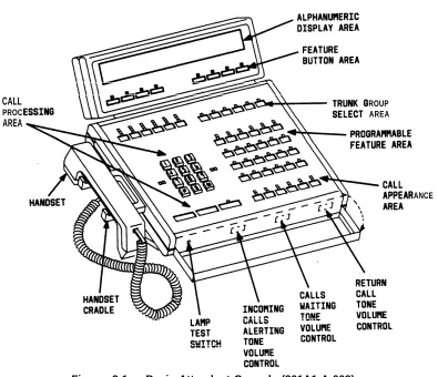
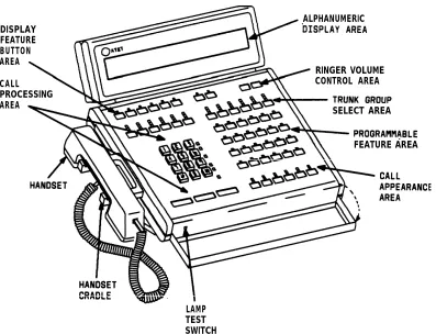
This chapter describes the two attendant console models: the Basic (Figure 2-1 ) and the Enhanced Attendant Console (Figure 2-2), and the
Attendant Console two models of the optional selector console (Figures 2-3 and 2-4). The call information displays and tones associated with console functions are also defined.
The attendant console is used to answer and extend incoming calls, to place outgoing calls, to provide information and assistance to inside and outside parties, and to manage and monitor some
Attendant
system operations.
Console
This desk-top unit is a digital call-handling position with push-button controls and lamps grouped in functional areas as shown in Figures 2-1 and 2-2. The differences in the functional areas between the models are described later in this chapter. The attendant console can be used alone or with the selector console.
The attendant console has jacks on each side for use with the handset supplied with the console or with a headset. The handset cradle, which is not a switchhook, can be mounted on either side. The K-type handset provided with the Enhanced Attendant Console can also be used with the Basic Attendant Console but the R-type handset provided with the Basic Attendant Console cannot be used with the Enhanced Attendant Console. Also, any headset that currently works with the Basic Attendant Console will work with the Enhanced Attendant Console.
Selector Console
Two selector console models are available: Basic Selector Console and Enhanced Selector Console. The Basic Selector Console, if used, can be paired with either the Basic Attendant Console or the Enhanced Attendant Console. The Enhanced Selector Console, if used, can be paired with either the Basic Attendant Console or the Enhanced Attendant Console.
The selector console is an adjunct to the attendant console. It provides the Direct Extension Selection (DXS) With Busy Lamp Field (BLF) feature. This feature provides a visual indication of the busy or idle status of the extension numbers assigned to the system. Calls are placed by pressing a Group Select button and a DXS button.
Functional Areas
This part contains descriptions of the following attendant console functional areas:
• Trunk Group Select Area • Call Appearance Area • Call Processing Area • Feature Area
• Alphanumeric Display Area
• Ringer Volume Control Area (Enhanced Console Only) • Selector Console Area.
CALL ROUP
PROC AREA
AREA
ANCE
Figure 2-1. Basic Attendant Console (301A1-A-003)
ALPHANUMERIC DISPLAY
FEATURE BUTTON AREA
RINGER VOLUME
CALL CONTROL AREA
PROCESSING
SELECT AREA AREA
FEATURE AREA
LAMP TEST SWITCH
Figure 2-2. Enhanced Attendant Console (302A1-A-003)
DXS/BLF TONS
HUNDREDS GROUP SELECTION BUTTONS
E
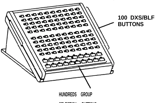
100 DXS/BLF BUTTONS
HUNDREDS GROUP SELECTION BUTTONS
Figure 2-4. Enhanced Selector Console (27A1-A-03)
Trunk Group Select Area
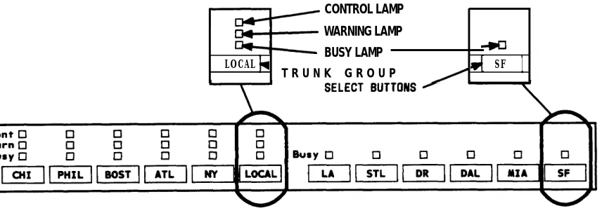
The Trunk Group Select buttons and associated lamps (see Figure 2-5, Basic Console, and Figure 2-6, Enhanced Console) function as follows:
• Trunk Group Select Button
Provides direct selection of an outgoing trunk group. Each button can be labeled to show the assigned trunk group. A Trunk Group Select button can also be used for direct selection of a code calling or loudspeaker paging zone.
• Busy Lamp
Lights when all trunks in the associated trunk group are busy.
• Warn (Warning) Lamp
Lights when a preset (by the System Manager) number of trunks are busy in the associated trunk group.
• Cont (Control) Lamp
Lights when the Attendant Control of Trunk Group Access feature is activated for the associated trunk group.
CONTROL LAMP WARNING LAMP BUSY LAMP
LOCAL SF
T R U N K G R O U P
1
NOTE : BUTTONS ARE LABELED AS AN EXAMPLE ONLY.
NOTE: BUTTONS ARE LABELED AS AN EXAMPLE ONLY.
Call Appearance Area
The call appearance buttons and associated Iamps (see Figure 2-7) function as follows:
• Call Appearance Button
Press to answer and originate calls.
Calls always come in on the leftmost idle call appearance button.
The call appearance is idle when both status lamps are dark.
• Atnd (Attendant) Lamp
Lights when the attendant is using the associated call appearance.
Flashes when an incoming was not answered and has • Hold Lamp
call needs answering or when an attendant-extended call returned to the console for further assistance.
Lights when a call is held on the associated call appearance
Flashes when time expires for the following held calls, and the call returns to the console for further assistance:
— Single-party call
— Attendant-extended call that was not answered.
Call Processing Area
This area (see Figure 2-8, Basic Console, or Figure 2-9, Enhanced Console) has buttons, lamps, and a touch-tone dial. The Cancel, Start, and Release buttons are used to process calls and activate features. The lamps show console status and system alarm status.
Figure 2-9. CalI Processing Area, Enhanced Console The buttons and lamps function as follows:
Buttons
• CancelCancels an attempt to extend a call to a busy or misdialed extension number or trunk, silences the tone, and automatically reconnects any parties that have been split (separated) from the connection. If only the attendant is active on the call, dial tone is returned after Cancel is pressed.
Disconnects the last party the attendant added to a conference call or the only party on a connection.
• Start
Obtains dial tone automatically and allows a call to be originated or extended.
When Start is pressed, any parties on the call are split from the connection, and the Split lamp lights. To reconnect the split parties,
Buttons.”
• Release
Releases the attendant from a call and readies other parties on the call remain connected.
refer to the Split button in “Feature
the console for the next call. Any
Lamps
• Alarm and Alarm Reported (Enhanced) or Alm-Ack (Alarm-Acknowledge) (Basic). The Alarm or Alm lamp (left lamp) lights when a system alarm is detected. Both lamps light when the Customer Support Service Organization (CSSO) is notified. The Alarm Reported lamp or the Ack lamp flashes if the system was unable to notify the remote maintenance center. Both lamps go dark when the alarm condition is cleared or when there is no alarm.
• Calls Waiting (Enhanced and Basic) and Calls Waiting Warning (Enhanced)
The Calls Waiting lamp lights when calls made to the attendant group number (0) or the listed directory number are waiting in the attendant group queue to be answered. The Calls Waiting (Enhanced) lamp and the lamp on the left (on the Basic) lights when at least one call is waiting to be answered. The Calls Waiting Warning (Enhanced) lamp and the lamp on the right (on the Basic) lights when the calls waiting exceed the limit preset (by the System Manager) for the system.
Calls waiting in the queue of the attendant’s individual extension number are indicated by the top lamp over the Forced Release button (all system versions of basic console except V1) or the Individual Calls Waiting lamp (enhanced console o n l y ) .
• Individual Calls Waiting (Enhanced Console Only)
The Individual Calls Waiting lamp lights when calls made to the attendant’s individual extension number are waiting in queue to be answered. The Individual Calls Waiting lamp lights when at least one call is waiting to be answered.
• Pos Avail (Position Available)
The Pos Avail lamp lights when the console is available for calls to the attendant group. This lamp does not indicate whether or not the console is available for individual attendant (Version 2, Version 3, and Generic 1 ) calls.
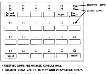
Feature Area
Feature buttons provide access to many of the system’s features and make call handling e a s i e r . Five buttons, one each for Split, Hold, Forced Release, Night, and Position Busy appear on every attendant console. The location of these feature buttons is the same on the attendant consoles used in V1, V2, and V3 systems. For Generic 1 systems only, the location of Split and Forced Release is the same. The location of the Hold, Night, and Position Busy buttons can be changed; however, they must appear in the Feature Area of the attendant console of ail Generic 1 systems. The System Manager can assign the remaining 19 buttons as optional feature buttons on attendant consoles used in all systems or as Hundreds Group Select (HGS) buttons in Generic 1 systems only, based on the needs of the individual
attendant. .
The location of the fixed feature buttons within the Feature Area of the attendant console is shown in Figure 2-10. Figure 2-10 also shows where the software locates the Night, Position Busy, and Hold buttons on the attendant console. The buttons and associated lamps function as follows:
Feature Buttons
• Split
Calls are split from the console when the attendant, active on a call, wants to talk to another party privately and presses the desired button to originate another call on the same call appearance. The original party is split away and the attendant can talk to the new party without the original party hearing the conversation. If the attendant presses the Split button, the original party and the attendant are conference together.
• Hold
Places a call on hold. The Hold lamp associated with the call appearance button lights steadily. The Hold lamp is described in “Call Appearance Button Area. ”
• Forced Release
Releases the attendant and disconnects all parties on an active trunk-to-trunk connection established by the attendant.
With all system versions except V1, the top lamp associated with the Forced Release button (Basic Console only) lights when a call is waiting in the attendant’s individual queue. For Enhanced Consoles, the Individual Calls Waiting lamp located in the Call Processing Area lights.
.
• Night
Places switch in night service. Then only the console administered as the “night” console will receive calls to the attendant group. Also, trunk group calls (other than calls on trunk groups with individual Trunk Group Night Service) will go to their assigned night destination.
The primary and daytime consoles are placed in the Night Service mode when the attendants go off duty. This makes the night console available for calls.
When the daytime attendants return to duty, the Night button is pressed to d e a c t i v a t e t h e N i g h t S e r v i c e m o d e . T h e N i g h t b u t t o n m u s t b e activated/deactivated at the principal’s console.
The lamp associated with the Night button lights at all consoles and voice terminals when the Night Service feature is activated and goes dark when the feature is deactivated.
• Pos Busy (Position Busy)
Places the console in a busy mode. Incoming calls to the attendant group cannot be received; however, calls can be originated. With V1 systems, Position Busy is denied if all other attendant positions are in the busy mode. With all other system versions, all attendants can be in the Position Busy mode at the same time. If all other attendants are in the Position Busy mode and the last available attendant activates Pos Busy, the top lamp (or the only lamp of a single-lamp button) of the Pos Busy button will flash at all the in-service attendant consoles in the attendant group.
* RESERVED LAMPS ARE ON BASIC CONSOLE ONLY.
† LOCATION SHOWN APPLIES TO
NOTE: UNLABELED BUTTONS ARE
VI, V2, AND V3 SYSTEMS ONLY. AVAILABLE FOR ASSIGNMENT.
Assigned Hundreds Group Select (HGS) Buttons (Generic 1 Only)
Should your console handle calls for an 800 line or greater system or a system with more than 8 hundreds groups and you do not have the Enhanced Selector Console, the System Manager may assign as many as 12 HGS buttons on the Feature Area of the Basic Attendant Console used with the Generic 1 system (Figure 2-1 O). The HGS buttons work the same way on the attendant console as they do on the selector console. Regardless of the location of the HGS buttons, a selector console must be used.
Note: With the Basic Attendant Console, 12 HGS buttons are located on the attendant console and 8 are located on the selector console. With the Enhanced Selector Console, all HGS buttons should be located on the selector console to make the feature buttons free for other features. All HGS buttons are assigned on the Attendant Console form.
The HGS buttons are labeled with the hundreds numbers used for the system dial plan. For example, for a 4-digit extension number system, these buttons can be labeled 21, 22, 34, and so on. On the other hand, these buttons can be labeled 1, 2, 3, and so on for a 3-digit system. The lamp associated with the HGS button lights when the button is pressed and remains lighted until a different HGS button is pressed. To use the Direct Extension Selection (DXS) buttons on the selector console, see “Using the DXS Buttons” in this chapter.
Assigned Feature Buttons
TYPICAL
BUTTON LABEL
Table 2-A. Attendant C o n s o l e F e a t u r e B u t t o n s
WHAT THE
BUTTON DOES
Activates Automatic Circuit Assurance referral.
Provides Abbreviated Dialing of a number or an access code.
Removes an agent from ACD call distribution in order for the agent to complete ACD-related activities such as forms completion.
Lamp flashes when the number of Attendant Queued Calls for the attendant group reaches an administered threshold; pressing the button displays the queue status.
Lamp flashes when the oldest call in the attendant group reaches an administered Attendant Queued Time threshold; pressing the button displays the queue status.
Places a call to a split supervisor.
Makes the user automatically available for new ACD calls upon completion of an ACD call.
Allows the attendant to enter a wakeup call for a guest (Hospitality Services feature) (V3 and G1).
Makes the console in a hunt group unavailable to incoming calls to the group (V3 and G1).
Lamp shows busy/idle status of the assigned trunk or extension number; button places a call to that facility (Facility Busy Indication feature).
Activates Busy Verification of Terminals and Trunks.
Associated lamp indicates that backup service is in effect. For V2, V3, and G1 only.
Cancels outward calling restriction for the voice terminal of a guest room when the room is occupied (Hospitality Services feature) (V3 and G1).
Table 2-Attendant Console Feature Buttons (Contd)
TYPICAL
BUTTON LABEL
WHAT THE
BUTTON DOES
Activates outward calling restriction for the voice terminal of a guest room when the room is vacated (Hospitality Services feature) (V3 and G1).
Displays an internal caller’s Class of Restriction.
. Changes the active routing plan to another routing plan on a specified day and time (Time-of-Day Routing feature, Generic 1 systems only).
Connects the covering party to the called party (principal) for private consultation (Call Coverage feature).
Activates Attendant Control of Trunk Group Access.
Deactivates Attendant Control of Trunk Group Access.
Associated lamp identifies an incoming call directed to a Coverage Answer Group.
Leaves a message for the principal to call the calling party.
Displays messages left for system users.
Silences Call Waiting ringback tone.
Displays the current date and time of day.
Deletes currently displayed message.
Allows the attendant to activate Do Not Disturb for an extension number (Hospitality Services feature) (V3 and G1).
Table
TYPICAL BUTTON LABEL
2-A. Attendant Console
Associated status lamp
Feature Buttons (Contd)
WHAT THE BUTTON DOES
lights if an off-board major, minor, or warning alarm is active on a DS1 circuit pack.
Associated lamp identifies an incoming Emergency Access to the Attendant call. For V3 and G1 only.
Associated status lights when a successful Facility Test Call ( F T C ) h a s o c c u r r e d .
Sends a call directly to coverage.
Identifies a specific trunk being used on a call.
Immediately changes the currently active routing plan to another routing plan (Time-of-Day Routing feature, G1 s y s t e m s o n l y ) .
Silences ringing associated with incoming calls.
Displays call-related information for a call on hold.
Accesses the Integrated Directory.
Allows the attendant to access local trunk groups on system (G1 only).
Activates Leave Word Calling; leaves a message for a called party to return a call.
Cancels a LWC message.
Associated lamp indicates that the assigned System Communication Interface link has failed.
Associated lamp indicates that a major alarm in the system is active.
Makes the console in a hunt group unavailable to incoming calls to the group (V1 and V2).
Table 2-A. Attendant Console Feature Buttons (Contd)
TYPICAL WHAT THE
BUTTON LABEL BUTTON DOES
Places a call to an extension number associated with a displayed message or Integrated Directory listing.
Prevents the user from becoming available for new ACD calls upon completion of an ACD call by automatically placing the agent in the after call work mode.
Associated lamp indicates that a message is left for another user and also turns on Msg Waiting lamp at another voice terminal.
Turns on the message indicator at a specified voice terminal (Hospitality Services feature) (V3 and G1).
Turns off the message indicator at a specified voice terminal (Hospitality Services feature) (V3 and G1).
Displays the next message or next name in directory.
Puts hunt group in night service.
Puts trunk group in night service.
Displays call-related information for the active call
appearance; pressing the button causes the user to exit the Message Retrieval, the Directory mode, or all other display modes and completes the Immediate Manual Override and Clocked Manual Override procedures.
Associated status lamp flashes if a call warning threshold has been reached.
Associated status lamp flashes if a time warning threshold has been reached.
Table
TYPICAL BUTTON LABEL
2-A. Attendant Console Feature Buttons (Contd)
WHAT THE BUTTON DOES
Activates AP Demand Print.
-
Associated lamp indicates a priority call.
Silences the Timed Reminder tone.
Releases an agent from an ACD call.
Allows the attendant to access trunk groups on remote system (G1 only).
Displays the number assigned to a button administered through the Facility Busy Indication feature.
Associated status lamp lights if the System has a problem that escalates beyond a warm start.
Displays elapsed time.
Displays the name of the trunk group being used on a CAS call and can also display the name of a trunk group
(administered for “no outgoing display”) used for an outgoing call (V3 and G1).
Lights when the interface to the primary SMDR output device has a problem.
Lights when the interface to the secondary SMDR output device has a problem (V3 and G1).
Associated status lamp is used to indicate that a System Printer interface failure has occurred.
Lights when the interface to the PMS Auto Wake printer has a problem (V3 and G1).
Lights when the PMS printer interface has a problem (V3 and G1).
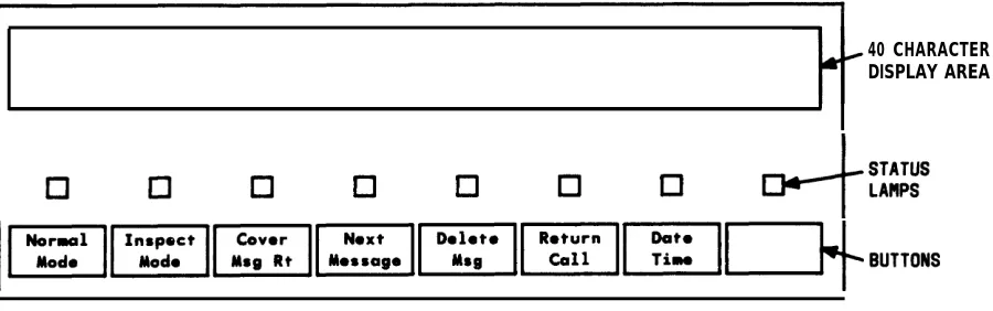
Alphanumeric
Display Area
The alphanumeric display area (Figure 2-11, Basic Console and Figure 2-12, Enhanced Console) contains a 40-character display. The Basic Console also has eight control buttons with their associated lamps located just below the display. The enhanced console has the equivalent buttons located at the top of the main faceplate.
40 CHARACTER DISPLAY AREA
NOTE : BUTTONS ARE LABELED AS AN EXAMPLE ONLY.
Figure 2-11. Alphanumeric Display, Basic Console
40 CHARACTER D I S P L A Y A R E A
Display Area
The 40-character display shows call-related information. Other information, such as messages left for voice terminal users, can also be displayed. The displayed information is described below.
Note: If your system has Integrated Services Digital Network (lSDN)—Primary Rate Interface (PRI) capability, refer to Chapter 4 for a description of the display information associated with the ISDN-PRI feature.
Call-related information includes the following:
• Call Appearance Identification
The six attendant call appearance buttons are labeled
a
through f. The display shows, for example,a=
for a call incoming on the first call appearance button,b=
for a call incoming on the second call appearance button, and so on.• Calling —
—
Party Identification
V1 Systems
When the call is from a system user, the display shows the caller’s extension number, the caller’s name, or a unique identification administered for the voice terminal being used. When the call is from outside the system, the display shows the trunk identification, such as CHICAGO, assigned to the trunk group used for the call.
Generic 1, V2, and V3 Systems
When the call is from a system user, the display shows the caller’s name or a unique identification administered for the voice terminal being used, along with the calling party’s extension number. When the call is from outside the system, the display shows the trunk identification, such as CHICAGO, and the trunk access code assigned to the trunk group used for the call.
• Called Party Identification — V1 Systems
On calls to a system user, the display shows the digits as they are dialed. After the dialing is complete, the display shows the called party’s name. If no name is assigned, the called party’s extension number is displayed.
On outgoing trunk calls, the display shows the digits as they are dialed, followed by the name assigned to the trunk group being used. The System Manager can suppress the name of any trunk group. If such a trunk group is accessed, the called party portion of the display is blank.
— Generic 1, V2, and V3 Systems
On calls to a system user, the display shows the digits as they are dialed. After the dialing is complete, the display shows the called party’s name and extension number. If no name is assigned, only the called party’s extension number is displayed.
On outgoing trunk calls, the display shows the digits as they are dialed, followed by the name and trunk access code assigned to the trunk group being used. The System Manager can suppress the name of any trunk group. If such a trunk group is accessed, the name portion of the display is blank.
• System User’s Class of Restriction (COR)
All system users have a COR to define their calling privileges. The COR is a 2-digit number followed immediately by a hyphen and a 4-character identifier.
With V1 systems, the display shows a user’s COR whenever the attendant places or answers an internal call. With all other system versions, the attendant must press the COR button to display a user’s COR. The COR information can be obtained from the System Manager.
The restriction identifiers are as follows: ORIG—Origination restriction OTWD—Outward restriction TOLL—Toll restriction CODE—Code restriction NONE—No restriction. • Call Purpose
This refers to calls that are directed, redirected, or returning to the console through an interaction with a feature. The call purpose identifiers are as follows:
co—Controlled Outward Restriction Call (V3 and Generic 1 systems)— Indicates that a call from an internal user has been redirected to the attendant because the user has Controlled Outward Restriction and has attempted to make an outgoing call.
es—Controlled Station-to-Station Restriction systems)—indicates that a call from an internal the attendant because the user has Controlled and has tried to make a station-to-station call.
ct—Controlled Termination Restriction Call (V3 and Generic 1 systems)— Indicates that a call has been redirected to the attendant because a user has Controlled Termination Restriction and the calling party has tried to call that user.
f—Call Forwarding —Shows that a system user has forwarded his or her incoming calls to the attendant.
hc—Held Call—Indicates that the preset time limit has expired for a call on hold at the console (applies only to V1).
ic—intercept Call—Indicates that the incoming call has been redirected to the attendant as a result of Intercept Treatment.
ld—DID LDN Call—Indicates that the incoming call is a Listed Directory Number (LDN) call on a Direct Inward Dialing (DID) trunk.
rc—Recall Call—Shows that a system user, active on a call held on the console, is requesting attendant assistance.
rt—Return Call—Shows that an attendant-extended call was not answered within the preset time and has returned to the console.
tc—Trunk Control—Shows that a system user tried to place an outgoing call, the Attendant Control of Trunk Group Access feature is active for that particular trunk group, and the call has been redirected to the console.
When the Call Coverage feature is active and the attendant is a covering user, the following call purpose identifiers will be displayed:
b—Busy— Indicates that the called voice terminal user is active on a call, and the called voice terminal user has a temporary bridged appearance of the call.
B—Busy— Indicates that the called voice terminal user is active on a call, and the called voice terminal user does not have a temporary bridged appearance of the call.
d—Don’t Answer or Cover—Indicates that the called voice terminal was not answered or that the calling system user has sent the call to coverage, or the called voice terminal user is not available. This identifier also indicates that the called voice terminal has a temporary bridged appearance of the call.
s—Send All Calls—Shows that the called system user is temporarily sending all calls to coverage.
Some typical displays are as follows:
• i n t e r n a l
• I n t e r n a l
call originated by the attendant (VI systems):
I
a=3602 .then
a = TOM BROWN 04-NONE I
or
a = EXT 3602 04-OTWD
a= TOM BROWN
3602
• Outgoing
Where
call originated by the attendant (V2, V3, and Generic 1 systems):
a = 3 6 0 2
then
3602
or
I
a = EXT 3602trunk call originated by the attendant (V1 systems):
b=87843541
8 is the trunk access code and 784-3541 is the number dialed.
then
b= OUTSIDE CALL
or
•
•
•
Outgoing trunk call originated by the attendant (V2, V3, and Generic 1 systems):
b=87843541
Where 8 is the trunk access code and 784-3541 is the number dialed.
then
b = OUTSIDE CALL 8
or
b= WATS 101
Where 101 is the trunk access code of the outgoing trunk group.
Incoming trunk call to the attendant (VI systems):
a= OUTSIDE CALL
Incoming trunk call to the attendant (V2, V3, and Generic 1 systems):
a = OUTSIDE CALL 102
Where 102 is the trunk access code of the incoming
Call from an inside user to the attendant (V1l systems)
trunk group.
•
a = PEARSON 04-OTWD
Where the calling user has Class of Restriction 04 and cannot place outgoing calls.
• Call from an inside user to the attendant (V2, V3, and Generic 1 systems)
a = PEARSON 5402
• Incoming trunk call extended to an inside voice terminal, now returning to the console:
I
e= OUTSIDE CALL to EXT 4328 r t• Conference call originated by the attendant:
b= CONFERENCE 4
Where 4 is the number of conferees, not including the attendant.
• Internal call redirected to coverage:
b= E X T 3 1 7 4 t o E X T 3 0 7 7 d
or
b = BOB SMITH to ANN JONES d
Where d indicates that the call was not answered and was redirected due to the Don’t Answer criterion of the Call Coverage feature.
• Incoming trunk call redirected to coverage:
b= OUTSIDE CALL to DON SMITH S
• Coverage Message Retrieval
IN PROGRESS
I
then
M E S S A G E S F O R B E T T Y R . S I M S
then
JOE JONES 10/16 11:40a 2 CALL 3124
This display means that Joe Jones called Betty R. Sims the morning of October 16. The second message was stored at 11:40 a.m. Joe wants Betty to call his extension number, 3124.
• Integrated Directory mode:
CARTER, ANN 3408 3 I
This display shows the name and extension number as administered in the system. The 3 indicates that three buttons were pressed to search for and display this particular directory listing.
Buttons and Lamps (Basic and Enhanced Consoles)
The eight buttons and associated status lamps on the Basic and Enhanced Consoles indicate the display mode. On the Basic Attendant Console, these buttons and lamps are located on the display module. On the Enhanced Attendant Console, these buttons and lamps are located on the main console. When the status lamp associated with the Normal Mode button is lighted, the alphanumeric display is in the Normal mode. When the Inspect Mode button is pressed, the Inspect Mode button status lamp lights, the Normal Mode button status lamp goes dark, and the alphanumeric display is in the Inspect mode. To return to the Normal mode, the attendant presses the Normal Mode button again.
The following display functions are available on the buttons. The function of each button may be changed by the System Manager.
• Normal Mode (Required Button)
• Inspect Mode
Displays call-related information on held calls when the attendant is active on a call. The attendant can press this button at any time. For example, the attendant is active on call appearance button b, and a call is held on call appearance button a. T h e attendant can press the Inspect Mode button and call appearance button a to display the information associated with the call on button a.
• Date Time
Displays the current time of day and date. The display will return to the previous information after 5 seconds. For example, the attendant presses the button, and the display shows the following:
10:23 am FRIDAY NOVEMBER 30, 1989
• Timer (Elapsed Time)
Displays elapsed time in hours, minutes, and seconds. The timing starts when the button is pressed and stops when the button is pressed again. The second button press also removes the elapsed time from the display.
The Timer button can be used any time the attendant wants to record the time spent on a particular call or operation. An example of the display is as follows:
a = OUTSIDE CALL :1:03
This example shows that the attendant has been active on an outside call on call appearance button a for 1 minute and 3 seconds.
• Cover Msg Rt (Coverage Message Retrieval)
Retrieves Leave Word Calling (LWC) messages for voice terminal users.
• Next
Displays the next stored LWC message or displays END OF MESSAGES, NEXT TO REPEAT when in the Cover Msg Rt mode. Displays the next name in the directory when in the Integrated Directory mode.
• Delete Msg (Message)
Deletes the displayed message.
• Make Call
• lntgrtd Directory (integrated Directory)
Displays names and extension numbers from system directory.
Ž Stored Number
.
Displays the trunk access code or the extension number of the facility being monitored by a Busy (Facility Busy Indication) button. This is accomplished by pressing the Stored Number button followed by the Busy button.
Ringer Volume Control Area (Enhanced Console Only)
The ringer volume control area on the Enhanced Attendant Console is shown in Figure 2-12a. This area consists of an Up button (labeled with an up arrow), a Down button (labeled with a down arrow), and a Select button. Three different ringer volumes can be adjusted. These are the incoming calls, calls waiting, and timed reminder tone volumes. These are the same volumes that are adjusted by the three slide switches located on the front panel of the Basic Attendant Console. Ringer volume can be adjusted for each of these tones in either of the following two conditions:
• While the ringer is on (tone is present).
Pressing and releasing the Up or Down button, while the appropriate tone is present, varies the volume of the tone. When this is done, a bar graph appears on the attendant display, along with the name of the tone. The bar graph shows the volume level of the tone being heard. To change a tone volume, push one of the volume control buttons several times while the tone is present. As this is done, the volume and the bar graph will change. Holding the button after pushing does not affect tone volume any more than a quick push and release.
• While the ringer is off.
To change the ringer volume while a tone is not present, simply press and release the Up or Down button. When this is done, a bar graph appears on the attendant display, along with the name of the tone. The bar graph shows the volume level of the tone indicated on the display. The volume of that tone can be changed by pressing and releasing the Up or Down button the required number of times. As this is done, the bar graph will change.
The first ringer volume that is displayed when the Up or Down button is pressed is the “incoming calls” ringer volume. The display will show “incoming call volume” along with the bar graph. While the incoming calls volume is displayed, the volume of the other two tones may be changed by first pressing the Select button (once for the Timed Reminder tone or twice for the the Call Waiting tone) and then pressing the Up or Down button the appropriate number of times.
The Select button is used to select the tone for which you wish to change the volume. As this button is pressed, the display is updated with the tone name and the volume level bar graph. However, this button only functions as the Select button while ringer volume information is displayed. Otherwise, the Select button serves as
one of the eight display buttons. When one of the Up or Down buttons is pressed, the volume level information is displayed for 5 seconds. It is during this time that the Select button can be used. The volume adjust mode can be deactivated before the 5-second time limit expires, by pressing any other button on the console.
* “TIMER” IS THE DEFAULT VALUE FOR THIS BUTTON. HOWEVER, THIS VALUE MAY BE CHANGED VIA SYSTEM ADMINISTRATION , RESULTING IN A DIFFERENT BUTTON NAME.
Figure 2-1 2a. Ringer Volume Control Area
Selector Console Area
The selector console consists of:
• Hundreds Group Select (HGS) Buttons and Associated Lamps
The HGS buttons (8 buttons on the Basic model [Figure 2-13] and 20 buttons on the Enhanced model [Figure 2-14]) are labeled with different hundreds group numbers used for the system. For example, for a 4-digit extension number system, these
buttons can be labeled 21, 22, 34, and so on. On the other hand, these buttons can be labeled 1, 2, 3, and so on for a 3-digit system. The lamp associated with the HGS
button lights when the button is pressed and remains lighted until a different HGS button is pressed.
Additional group select buttons may be assigned to feature buttons. This allows a console with a Basic Selector Console to access 20 hundreds groups.
• Direct Extension Selection (DXS) With Busy Lamp Field (BLF)
DIRECT EXTENSION SELECTION ( DXS) BUTTONS
FIELD (BLF) LAMPS
Direct
NOTE: GROUP SELECT BUTTONS ARE LABELED AS AN EXAMPLE ONLY.
Figure 2-14. Enhanced Selector Console Area
Extension SELECTION
(Dxs) BUTTONS
BUSY LAMP F I E L D ( B L F ) L A M P S
Using the DXS Buttons
The attendant presses the appropriate HGS and DXS buttons to extend and originate calls to system users.
An extension number has two, three, four, or five digits:
• A 2-digit extension number has a 2-digit DXS number but does not have a select number. For example, the extension number 21 has a 21 DXS number.
group
• A 3-digit extension number has a 1-digit group select number and a 2-digit DXS number. For example, the extension number 321 has a 3 group select number and a 21 DXS number.
• A 4-digit extension number has a 2-digit group select number and a 2-digit DXS number. For example, the extension number 4321 has a 43 group select number and a 21 DXS number.
• A 5-digit extension number has a 3-digit group select number and a 2-digit DXS number. For example, the extension number 54321 has a 543 group select number and a 21 DXS number.
Determining Extension Number Status
The attendant determines the idle or active status of extension 4321 or 321 by pressing Group Select button 43 or 3 and looking at the lamp to the left of DXS button 21. If the lamp is dark, the extension is idle. A call can be extended or originated to that number.
If the lamp is lighted, the call can still be extended. The extension number may be active, but another answering group member may be available or another call appearance may be idle on a multi-appearance voice terminal. Also, the Attendant Call Waiting feature can be activated for a single-line voice terminal. (Attendant Call Waiting is described in Chapter 4.)
When the number represented by the DXS button is assigned to a group, such as a terminating extension group or trunk group, the lamp lights only when all members of the group are busy and the queue, if provided, is full.
If all available call appearances on a multi-appearance voice terminal are active or if the Attendant Call Waiting feature cannot be activated, the attendant hears busy tone.
Attendant Console Tones
Tones Heard Through Handset or Headset
While operating the console, the following tones may be heard through the handset or headset:
Ringback Tone
Busy
A low-pitched tone repeated 15 times a minute; the electronic version of the conventional ringing heard when the number dialed is being rung.
Tone
Confirmation Tone
Three short bursts of tone; indicates that the feature operation requested (activated or deactivated) has been accepted.
Coverage Tone
One short burst of tone; indicates that a call to an extension number will be answered at another extension number by a covering user.
Dial Tone
A continuous steady tone; indicates that the system will accept dialing or that a feature can be activated.
Intercept Tone
An alternating high and low siren-type tone; indicates either that the number was dialed incorrectly or that a feature request is denied.
Reorder Tone
A fast busy tone repeated 120 times a minute; indicates either that all trunks within a particular trunk group are busy or that the feature requested is not currently available. After hearing reorder tone, the call or feature request can be attempted again later.
Call Waiting Ringback Tone
A low-pitched tone identical to the ringback tone except that the volume decreases during the last 0.2 second of tone. Indicates that the Attendant Call Waiting feature is activated and that the called voice terminal user is aware of the waiting call.
Tones Generated at Console The attendant console
handset:
Ringing
An on-off,
also generates the following tones that are not
low-pitched tone; indicates that an incoming call
Calls
console call appearance button and is waiting to be answered.
heard through the
is connected to a
Waiting Tone
An on-off, medium-pitched tone; indicates that one or more incoming calls are waiting in queue to be answered.
Timed Reminder Tone
A high-pitched tone, on for about 1/3 second and off for about 1 second; indicates that a single-party call has been on hold at the console for longer than the preset time. This tone is also heard when the Attendant Recall feature is activated and when an unanswered attendant-extended call returns to the console.
Emergency Access Tone (V3 and Generic 1)
CHAPTER 3. OPERATING THE CONSOLE
This chapter contains the procedures that you must use to answer, place, release, split, extend, and hold calls. You will also apply these procedures, in whole or in part, to other call-handling tasks such as activating some of the attendant and system features.
Activating and Deactivating the Console
Activate (turn on) the console by plugging in the handset or the headset. If the Night lamp is lighted and you are the primary attendant, press (Night) to put the primary console and any other daytime consoles into normal day service.
Deactivate (turn off) the console by pressing (Night) or by unplugging the handset or the headset. (Night Service is described in Chapter 4.)
Answering Calls
An incoming call is identified by 1-burst repetitive ringing, flashing Atnd lamp above one of the six call appearance leftmost idle call appearance button.
a dark Pos Avail lamp, and a buttons. Calls come in on the
The console’s alphanumeric display provides calling party information as described in “Alphanumeric Display Area” in Chapter 2. The display clearly distinguishes between calls from users inside the system and calls from outside.
Emergency Calls
A special type of incoming call that requires immediate attention is an emergency call from an inside voice terminal user (Generic 1 and V3 systems).
Always answer an emergency call as soon as it arrives.
You will be alerted to an emergency call by the following special indications:
• The Emergency lamp in the assigned feature button area flashes. • A special emergency tone sounds (normal ringing on older consoles).
• The display identifies the calling party and shows the abbreviated word EMRG. The procedures for answering an emergency call are the same as those used to answer other incoming calls.
all
To answer an incoming call:
1. Press the call appearance button where the Atnd lamp is flashing. Ž Ringing stops.
• Atnd lamp lights steadily. • Pos Avail lamp remains dark. Ž Console is connected to the caller.
2. Answer the call and assist the caller as necessary.
• The incoming call can now be extended (see Extending Calls), held (see Holding Calls), or ended (Step 3).
3. To end the call, press (Release).
• Console is disconnected from the caller. Ž Display and the Atnd lamp go dark. • Pos Avail lamp lights.
• Console is now ready to answer or place another call.
Placing Calls
You can place calls to extension numbers inside your system and calls to outside numbers through trunks. The steps for placing these types of calls are distinctly different and are described in the following two procedures. Called party information is displayed as described in Chapter 2.
Calls to Inside Extension Numbers
You can place a call to any extension number in the system. You may use the selector console if you have one; otherwise, select an idle call appearance and dial the number.
To call an extension number inside the system:
1. If you have a selector console, place the call using Steps 2 and 3 or Steps 4 and 5. If you do not have a selector console, place the call using Steps 4 and 5.
• If the DXS lamp is dark, the extension is idle; go to Step 3.
• If the DXS lamp is lighted, the extension is active; you can still place the call, but it may wait or go to a covering party.
3. Press the DXS button for the desired extension number; observe the lamps, and listen for call progress tone.
• The Atnd lamp at the idle call appearance button lights. • Pos Avail lamp goes dark.
• Ringback; if call is answered, go to Step 6. If call is not answered, go to Step 7 or 8.
Ž Call waiting ringback; wait for answer, go to Step 6.
• Busy tone; go to Step 7 or 8.
• Intercept tone— unassigned number dialed; go to Step 7 or 8.
• Dial tone. 4. Press (Start).
• Atnd lamp at idle call appearance lights. • Pos Avail lamp goes dark.
5. Dial the desired extension number and listen for call progress tone. • Tones same as Step 3.
6. Talk to the called party; when the conversation is finished, press (Release). • Atnd lamp and the display go dark.
• Pos Avail lamp lights. • Procedure complete.
7. To try to call the same number again or place another call immediately, press (Cancel); return to Step 1.
3-3 • Call progress tone stops.
8. To abandon the call attempt, press (Release). • Call progress tones stop.
• Atnd lamp and the display go dark. • Pos Avail lamp lights.
• Procedure complete.
Calls to Outside Numbers
An outside call requires an outgoing trunk as well as dialing of the distant number. You can access a trunk in two ways:
1. Dial an access code for a Private Network, Automatic Alternate Routing (V2, V3, and Generic 1 systems), Automatic Route Selection, or a specific trunk group.
2. Press the Trunk Group Select button for the desired trunk.
To call an outside number:
1. Decide whether to access an outgoing trunk by dialing a code (Steps 2 and 3) or by using a Trunk Group Select button (Steps 4 and 5).
2. Press (Start). • Dial tone.
• Atnd lamp at idle call appearance button lights. • Pos Avail lamp goes dark.
3. Dial the trunk access code, and listen for call progress tone. • Second dial tone—valid code; go to Step 6.
• Reorder tone—no outgoing trunk available; go to Step 8 or 9. • Intercept tone —invalid code; go to Step 8 or 9.
4. Check the status of the Trunk Group Select lamps. • No lamps lighted—trunk available; go to Step 5.
• Busy lamp lighted—all trunks in the group are busy; try again later.
5. Press Trunk Group Select button.
• Atnd lamp at idle call appearance button lights. • Pos Avail lamp goes dark.
• Dial tone; go to Step 6.
6. Dial the outside number, and listen for call progress tone.
• Ringback; if call is answered, go to Step 7. If call is not answered, go to Step 8 or 9.
• Busytone; go to Step 8 or 9.
• Intercept tone—call cannot be completed as dialed; go to Step 8 or 9.
7. Talk to the called party; when the conversation is finished, press (Release). • Atnd lamp and the display go dark.
• Pos Avail lamp lights. • Procedure complete.
8. To try to call the same number again or place another call immediately, press (Cancel); return to Step 1.
• Call progress tone stops. • Dial tone starts.
9. To abandon the call attempt, press (Release.) • Call progress tone stops.
• Atnd lamp and the display go dark. • Pos Avail lamp lights.
• Procedure complete.
Releasing Calls
As the previous procedures have shown, you press (Release) to end a call. The following results always occur:
• Console is disconnected from the called or calling party (or both if they are connected together).
• Atnd lamp and the display go dark.
• Pos Avail lamp lights (unless another call is coming to the console). • Call progress tones stop.
• No dial tone heard.
• Console is ready for answering or placing another call.
In the rest of this guide, the normal results of releasing a call listed above will not be specified again.
Holding Calls
Single-party and multi-party calls can be put on hold at the console. It is possible to have a held call at each of the six call appearances. You should hold a call if the party (or parties) may need assistance later or if you expect to reenter the call with information.
To hold a call on the console:
1. With the call active on a call appearance, press (Hold). • Hold lamp at the hold button lights.
• Hold lamp at the call appearance button lights. • Atnd lamp and the display go dark.
• Pos Avail lamp lights.
To reenter a single-party call held on the console:
1. Press the call appearance button where the call is on hold.
• Hold lamp goes dark. .
• Atnd lamp lights.
• Pos Avail lamp goes dark.
• Held party is reconnected to the console. 2. Talk to the other party.
You can manually reenter a single-party held call at any time using the last procedure. However, a single-party call on hold returns to the console automatically when the preset timed reminder interval expires. (Refer to Timed Reminder feature in Chapter 4.)
When the timed reminder interval expires for a call, the Hold lamp at the call appearance button flashes, timed reminder tone sounds, and the alphanumeric display identifies the call. Answer the returning call in the same way that you answer any incoming call, and assist the caller as necessary.
If the held call has two or more parties, the Attendant Lockout feature prevents you from directly reentering the call. One of the parties on the call must call you for assistance (the Attendant Recall feature). Multi-party calls held at the console are not timed; therefore, timed reminder does not apply to them. (Attendant Lockout and Attendant Recall are described in Chapter 4.)
Splitting Calls
The Attendant Auto-Manual Splitting feature lets you temporarily disconnect from a caller, place a call to another party, and then connect the two parties together. Splitting is a procedure that you must always perform in order to extend an incoming call to an inside or outside number. Splitting allows you to take the following steps:
1. Either talk with the second party to announce the waiting call or drop out of the call before the second party answers.
2. Connect the two calls together.
3. Join the calling and called parties in a 3-way connection from which you can later drop out.
4. Return to the split caller if the called party does not answer or declines to enter the call.
This feature is activated automatically when you perform any one of the following actions after answering an incoming call:
1. Press the Start button.
2. Call an extension number using the Selector Console. 3. Call an extension number using Start and dialing. 4. Press a Trunk Group Select button.
While the caller is split from the console, the Split lamp is lighted. The split condition is canceled, and the Split lamp goes dark when you do one of the following procedures:
1. Press the Release button to connect the split party to the called party and disconnect the console.
2. Press the Split button to establish a 3-way connection with you, the caller, and the called party. If the called
returns you to the caller.
3. Press the Cancel button to caller.
party has dropped off, pressing the Split button simply
cancel the outgoing call attempt and reconnect you to the
All the steps for activating and deactivating the split condition are integrated into the next procedure, “Extending Calls.”
Extending Calls
Extending a call means, basically, to transfer a call from the console to another destination. Calls can be extended to an inside extension number or to an outside number through a trunk. Extending a call consists of answering an incoming call, splitting, placing another call, and then connecting the two calls together. Once a call is extended, you can release from the call or remain connected.
The following procedures for extending calls combine the basic call-handling steps already presented in this chapter. In all cases, calls that have been extended can be held at the console rather than released.
You will extend calls for the following reasons:
• A party on an incoming call requests to be connected to an extension number inside the system. The incoming call will normally be a trunk call from outside the system,
but it can be from an inside extension number.
• A party on an incoming trunk call requests to be connected to an outside number on another trunk.
To extend an incoming call to an inside extension number:
1. After answering the incoming call, tell the caller that you are going to break the connection temporarily (split) while you call the other party.
2. Call the desired party using the normal procedures for placing a call to an inside extension number.
• Split lamp lights.
3. Use one of the following steps, 4 through 7, to complete the call.
4. If you are not going to announce the call, press (Release) as soon as the call starts ringing.
• Calling party is connected to the ringing line. • Split lamp goes dark.
• Procedure complete (unless the call is unanswered and returns to the console; refer to Timed Reminder feature in Chapter 4 for details).
5. If you are going to announce the call, wait for the called party to answer. If the called party accepts the call, press (Release).
• Caller is connected to the called party.
• Split lamp goes dark. • Procedure
If the called party hangs up.
• Console is
complete.
declines to talk to the caller, press (Split) after the called party
connected to the caller again.
• Split lamp goes dark.
Explain to the caller that the called party is not available. Take a message, or ask the caller to try again later; then press (Release).
• Procedure complete.
6. If the called party is busy or does not answer, press (Cancel). • Outgoing call is canceled.
• Call progress tone stops.
• Console is connected to the caller again. • Split lamp goes dark.
Explain to the caller that the called party cannot be reached. Take a message, or ask the caller to try again later; then press (Release).
• Procedure complete.
7. To set up a 3-way connection, press (Split) before or after the called party answers. • Console, caller, and called party are connected together.
• Split lamp goes dark.
To drop out of a 3-way connection, press (Release).
• Procedure complete.
To extend a call from an inside extension to an outside number: 1. After answering the incoming call:
• Determine whether the outgoing call can be allowed.
• Find out whether the caller wants to dial the outside number after you access a trunk or wants you to dial the entire call.
2. Tell the caller that you are going to break the connection temporarily (split) while you start the outgoing call.
3. Access an outgoing trunk using a trunk access code or a Trunk Group Select button. • Split lamp lights.
• Dial tone.
If a trunk is not available, again later.
4. If the caller wants to dial the outside number, press (Release). • Caller hears dial tone and can now dial the outside number. • Split lamp goes dark.
• Procedure complete.
5. If the caller wants you to complete the entire call, dial the outside number. 6. Use one of the following steps, 7 through 10, to complete the call.
7. If you are not going to announce the call, press (Release) as soon as the call starts ringing.
• Calling party is connected to the ringing line. • Split lamp goes dark.
• Procedure complete.
8. If you are going to announce the call, wait for the called party to answer. If the called party accepts the call, press (Release).
• Caller is connected to the called party.
• Split lamp goes dark. • Procedure complete.
If the called party declines to talk to the caller, press (Cancel).
• Console is connected to the caller again. • Split lamp goes dark.
Explain to the caller that the called party is not available. Take a message, or ask the caller
to try again later; then press(Release).
• Procedure complete.
9. If the called party is busy or does not answer, press (Cancel). • Outgoing call is canceled.
• Call progress tone stops. . • Console is connected to the caller again.
• Split lamp goes dark.
Explain to the caller that the called party cannot be reached. Take a message, or ask the caller to try again later; then press (Release).
• Procedure complete.
10. To set up a 3-way connection, press (Split) before or after the called party answers. • Console, caller, and called party are connected together.
• Split lamp goes dark.
• Procedure complete.
To extend an incominq trunk call to an outside number:
1. After answering the incoming call, tell the caller that you are going to break the connection temporarily (split) while you call the other party.
2. Call the desired party using the normal procedures for placing an outgoing trunk call. • Split lamp lights.
• If a trunk is not available, reorder tone is heard; press (Split) to reconnect to the caller. Ask the caller to try again later.
3. Use one of the following steps, 4 through 7, to complete the call.
4. If you are not going to announce the call, press (Release) as soon as the call starts ringing.
• Calling party is connected to the ringing line. • Split lamp goes dark.
5. If you are going the announce the call, wait for the called party to answer. If the called party accepts the call, press (Release).
• Caller is connected to the called party. • Split lamp goes dark.
• Procedure complete.
If the called party declines to talk to the caller, press (Split) after the called party hangs up.
• Cons