Report No. 472
COMPUTATIONAL DEVELOPMENT OF COMPOSITE PACKED-BED NANOFILTRATION FOR HIGH-THROUGHPUT DESALINATION
By
Yaroslava G. Yingling and James S. Peerless
Department of Materials Science & Engineering North Carolina State University
UNC-WRRI-472
The research on which this report is based was supported by funds provided by the North Carolina General Assembly and/or the US Geological Survey and the National Oceanic and Atmospheric Administration through the NC Water Resources Research Institute and NC Sea Grant.
Contents of this publication do not necessarily reflect the views and policies of WRRI or Sea Grant, nor does mention of trade names or commercial products constitute their endorsement by the WRRI, Sea Grant, the State of North Carolina, the US Geological Survey or the National Oceanic and Atmospheric Administration.
This report fulfills the requirements for a project completion report of the Water Resources Research Institute of The University of North Carolina and NC Sea Grant. The authors are solely responsible for the content and completeness of the report.
WRRI Project No. 16-12-W Sea Grant Project No. R/MG-1617
INTRODUCTION
Desalination of sea and/or brackish water has become an increasingly important process for the supply of clean municipal water in the U.S. and North Carolina in particular (Mickley 2012). However, there still exist many technical and economic challenges towards the efficient implementation of the dominant desalination technology, reverse-osmosis (RO). Hence, it is in line with the goals of the North Carolina Sea Grant (NCSG) and Water Resources Research Institute (WRRI) to explore alternatives to RO that may result in inexpensive and effective removal of ionic species from water sources. In this report, the results of a study to use atomic-scale computational methods to develop and test a novel packed-bed nano-filtration architecture for the removal of charged species are discussed.
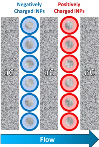
The target architecture, as described in the proposal, consists of layers of commonly available amorphous carbon (aC) as a scaffold for functionalized inorganic nanoparticles (INPs), as shown in Figure 1. The proposed design makes use of well-known absorption properties of aC along with the highly chemically selective functionalization options and high surface area of INPs. For example, the schematic shown in Figure 1 uses INPs with negatively charged functional groups to immobilize positively charged ionic species (e.g. Na+, Ca2+, Pb2+, B3+), and INPs with positively charged
functional groups to adsorb negatively charged ionic species (e.g. Br-, Cl-, F-, NO
3-, CN-).
In the proposal a variety of inorganic materials to comprise the INP cores were discussed including silver, gold, and silica. In the performed work, we first focused on INPs with gold cores given the ease of functionalization, chemical inertness, as well as the well-developed atomistic models previously employed by members of the Yingling Group (Nash, Singh et al. 2015).
The primary goal of the study outlined in the proposal was to develop a computational methodology by which the functionalization chemistry applied to the INPs can be evaluated and adjusted without the difficulties associated with chemical synthesis. During these initial stages we evaluated two sulfonated ligand chemistries: n-hexylamine (HA) and dipropylamine (DPA), shown anchored to gold INPs in Figure 2. The choice of these ligands as test systems was two-fold: a) the ligands have the same chemical formula but are measured to have different affinities for salt rejection in a solvent state, thus testing the sensitivity of the resulting assay, and b) the lack of formal charges (i.e., neither anionic or cationic) eliminates potential errors due to high ligand
ligand repulsion that may occur between like-charged ligands. Anionic and/or cationic ligands can be tested with a variety of ligand chemistries once the assay has proven reliable for moderately charged species such as HA and DPA.
Figure 2. Ligand chemistry for molecular dynamics experiments, a) n-hexylamine (HA) and b) dipropylamine (DPA), shown anchored to gold INP (large yellow spheres). Single ligand colored by element for clarity (yellow = sulfur, gray = carbon, white = hydrog en, blue = nitrogen).
METHODS
All-atom Molecular Dynamics (MD) simulations were employed to probe the atomistic behavior of nanoparticle-ionic solution systems. MD is a deterministic computational method that utilizes parameterized bonded and non-bonded interactions contained within a force field to solve the Newton’s classical equations of motion over a given timestep. The term “all-atom” denotes that each particle in the system represents a single atom, which allows for accurate parameterization of force fields from first-principles ab initio calculations. Hence, all-atom representations such as those in Figure 2 serve not only as schematics, but also an accurate representation of the particles accounted for during the simulation process. The benefits of this simulation method are that the high resolution allows for accurate parameterization and property calculation, all while remaining a high-throughput testing method relative to experimental synthesis and salt rejection assays.
Simulation systems were built and equilibrated utilizing in-house Python scripts and the AMBER 16 molecular dynamics package (Case, Betz et al. 2016). Sulfonated DPA and HA were parameterized using the general AMBER force field (Wang, Wolf et al. 2004) for bonded and van der Waals terms, while partial charges were derived from the restrained electrostatic potential (RESP) method from Gaussian ab initio calculations using the R.E.D. Server (Vanquelef, Simon et al. 2011). The TIP3P rigid water model was employed and the monovalent ion force field parameters by Joung and Cheatham (Joung, Cheatham 2008) were applied to the ionized species in solvent (Na+, Cl-). Force-field parameters for gold atoms were those used by our group in
While AMBER 16 was used for building systems and equilibrium simulations, many of the filtration tests were non-equilibrium simulation protocols such as steered MD that required the use of the NAMD MD package (Phillips, Braun et al. 2005). Thankfully, there are well-established protocols for converting AMBER trajectories and topologies for use in NAMD with AMBER simulation parameters. Post-processing was performed with the AMBER cpptraj program (Roe, Cheatham 2013) and in-house analysis scripts. Visualizations of MD trajectories were rendered with VMD (Humphrey, Dalke et al. 1996).
The primary goal of this project requires the invention of an in silico testing method for the packed-bed architecture described above as a method of salt rejection. Early in the design stages of the experiment, it became apparent that the construction of the aC scaffold in an all-atom simulation is neither a trivial nor well-established protocol (Marks, Bell et al. 2003). Indeed, the incorporation of a randomly structured aC structure on an atomistic length scale would likely introduce a large source of error due to the choice of initial structure. Given that the absorption properties of aC are well known, the choice was made to focus on the more synthetically demanding component of the proposed design, the functionalized INPs.
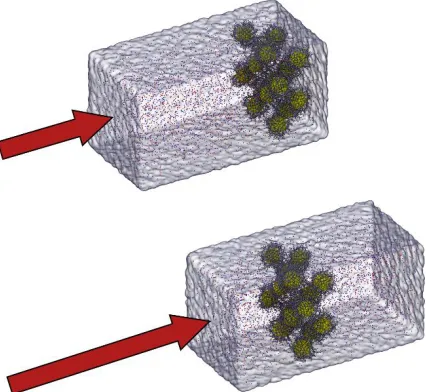
Hence, the following results cover the efforts to test immobilized INPs as a method of salt rejection, temporarily assuming that a) the INPs can be properly grafted to an aC scaffold and b) the functionalized INPs will be the driving force in salt rejection and flow dynamics. The latter assumption is likely as the diameter of the INPs studied (1.6 nm) is orders of magnitude smaller than the typical pore in a porous aC structure. This simplified objective is illustrated in Figure 3. We look to force a salt water solution through a bed of immobilized INPs functionalized with a given ligand chemistry and quantify the ability of the INPs to reject ionic species. Further simulation details specific to each methodology are described in the results and discussion section below.
RESULTS & DISCUSSION
simulations, the coordinates of these compressed INPs after equilibration were translated, rotated, and solvated to construct the initial coordinates for the assay tests.
EQUI LIBRI UM MEMBR ANES
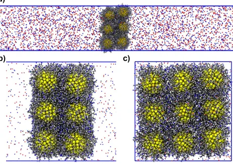
The first test discussed here is not a recreation of the filtration process as depicted in Figure 3. Rather, the following describes equilibrium simulations that serve to show that the force field parameterization is able to reproduce selectivity of salt rejection between INPs functionalized with HA and DPA. The simulation setup is depicted in Figure 4. The compressed INPs were taken directly from the compression simulation described above and solvated in each z-direction to 120 Å, resulting in a total box length of approximately 290 Å total. Given the periodic boundary conditions of the system in all three dimensions, the setup thus simulates an infinite membrane in the xy-plane immersed in water. Water molecules were then randomly replaced with Na+ and Cl
-ions to form a 1M NaCl solution. (Note that seawater is approximately 0.6M NaCl.)
Figure 4. Simulation setup for equilibrium membrane simulations for HA-functionalized INPs. Water not shown for clarity. Gold cores shown as large yellow spheres. Ions shown as small spheres colored by charge (red = negative, blue = positive). Periodic boundaries shown as blue lines. All other atoms colored by atom type. a) Full side view. b) Side view zoomed in on INPs. c) Front view.
the restraints on the INP cores were turned off, thus allowing the membrane to freely swell as water and ions could enter the gaps between the INPs and freely solvate them. However, given that both HA and DPA are hydrophobic, it is unlikely that full solvation would occur even at infinite time scales. The test was instead to highlight the differences in the absorption of water and ions between the two INPs by monitoring the amount of water and ions that penetrate the membrane over a given time – in this case 100 ns.
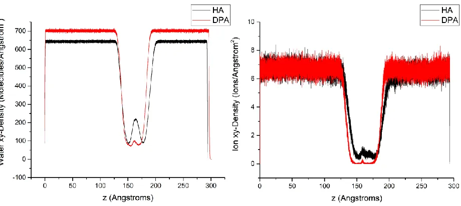
The average planar density of ions and water over the 100 ns production run are shown below in Figure 5. The planar density shows that the HA-functionalized INPs show a higher degree of penetration for both water and ionic species. This is accompanied by an increase in membrane thickness, as indicated by the wider trough in the HA water planar density data. Thus it can be said that the HA-functionalized NPs show a higher affinity for ions in equilibrium conditions, yet the efficacy for salt rejection is still unclear as a higher volume of water is also adsorbed.
Figure 5. Water (left) and ion (right) planar density for HA and DPA functionalized INPs during 100 ns equilibrium membrane simulations.
It should be noted that this result is in agreement with basic assumptions based on the structure of each ligand. Inspection of the ligand structure in Figure 2 reveals that the more polar (and thus more hydrophilic) amine group is at the end of the ligand for HA, while the amine is strongly shielded by propane groups in DPA. This likely accounts for the higher rate of water and ion adsorption by the HA-functionalized INPs. However, this does not preclude DPA from being successful at salt rejection, as in a pressurized-flow situation ions may be forced to penetrate the INP functional layer and be less inclined to release due to the hydrophobicity of the ligands around the amine group.
POR OUS PIST ON
simulation (2x2x1) to increase the computational throughput. A porous piston was constructed of non-physical dummy atoms placed in a square lattice 7.5 Å apart. (Note that this abnormally long bond length requires that the van der Waals cutoff parameter to be increased above the default value of 8 Å to greater than 15 Å.) The dummy atoms had no electrostatic interactions, but were given van der Waals parameters of sp3 carbon, the primary atom type in aC. The bonds between
the dummy atoms making up the porous piston were heavily restrained (300.9 kcal/mol force constant) to enforce the piston remained rigid. The porous piston and INPs are then solvated with 1M NaCl salt solution in the z-direction only, again simulating an infinite membrane in the xy-plane (see Figure 6).
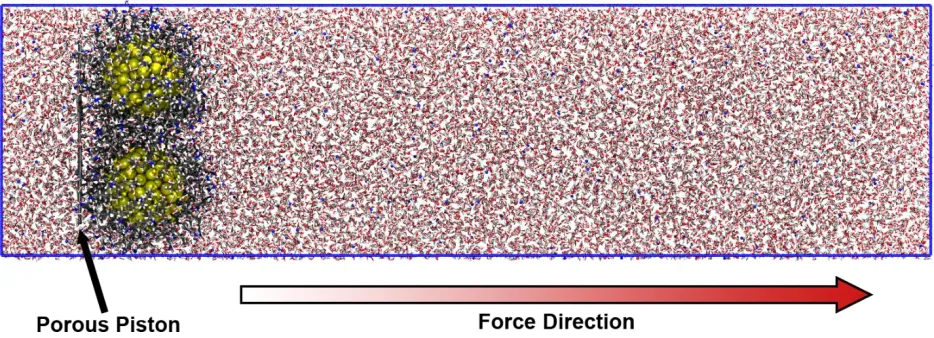
Figure 6. Simulation setup for HA-functionalized INPs with porous piston.
The system was first equilibrated to ensure that the salt water solution reached 300 K and 1 atm while only the INP cores and porous piston were heavily restrained by a harmonic function with a force constant of 100 kcal/mol. After this stage, filtration was simulated in NAMD by applying moving harmonic restraints to the porous piston (and only the piston atoms) during the production stage. In other words, all non-piston atoms are allowed to move freely in the system (though thermostatted to 300 K and 1 atm) while the piston atoms are tied to coordinates with a harmonic function with a high force constant (10 kcal/mol). The coordinates that the piston is tied to move at a constant linear velocity in the positive z direction (see Figure 6) of 1x10⁻⁵ Å/fs, which is
equivalent to 1 m/s or 2.2 mph. Thus, throughout the entire 20 ns production simulations, the porous piston transverses the entire 200 Å simulation box in the z-direction.
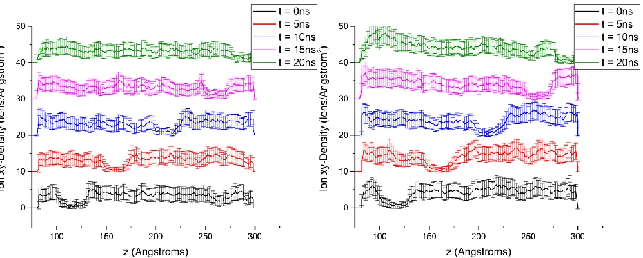
Figure 7. Planar ion density at different simulation times for porous piston simulations of (left) HA- and (right) DPA-functionalized INPs. Each density profile is averaged of 400 ps of simulation time, with error bars representing the standard deviation.
The data shown in Figure 7 has some intrinsic problems if it is to be used to draw conclusions about the macroscopic filtration efficacy of each functionalization. To begin with, one may note the error bars on the planar density data that are quite significant relative to the signals in the data. These error bars represent the standard deviation of these density values over the period for which the density values were averaged (400 ps). Thus, it becomes difficult to say with absolute certainty that the more pronounced peak in the DPA data would lead to experimentally significant improvements in salt rejection.
Moreover, the most clear indication of salt rejection would be a clear difference in planar ion density in front of the moving membrane as compared to behind it. This would show that the water in front of the INP membrane is increasing in ionic concentration while the water the membrane would show a reduced ion concentration, effectively filtering the salt solution. One may be tempted to say this is the case when observing the t = 10 ns data in Figure 7 (blue line), however, it must again be noted that the high standard deviation of planar ion density at each point indicated by the error bars makes any numerical reduction of these density changes insignificant.
GOLD PIST ON – FIXED CO RES
In an effort to address the ion diffusion problem discussed above, the simulation setup depicted in Figure 8 below was constructed. In the filtration experiment, instead of moving the INPs through the solution as described above, the INP cores would be fixed (note that only the cores are fixed; the ligands are free to move while remaining attached to the cores) and a solid non-porous piston would be used to push the salt solution through the membrane.
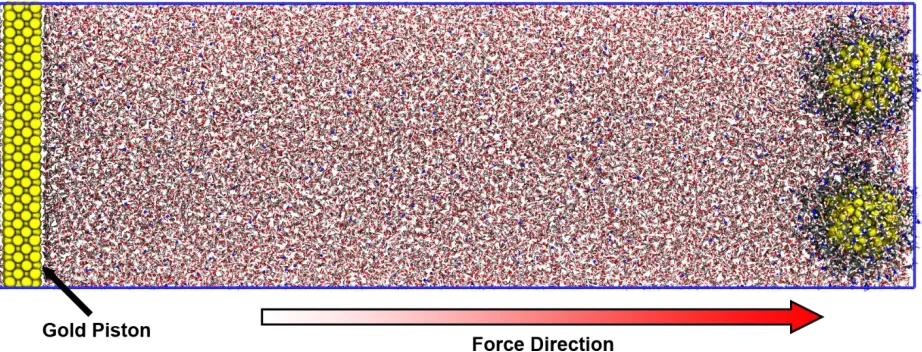
Figure 8. Simulation setup for HA-functionalized INPs with gold piston and fixed INP cores.
As with the above experiment, 4 INPs from the compression simulations were chosen as starting coordinates. Gold was chosen as the piston material as it required no additional parametrization (as the same parameters for the INP cores were used) and is representative of an inert piston material. Again, 1M NaCl solution was used to solvate the system. The system was brought to 300 K and 1 atm with the piston and gold core atoms harmonically restrained so that the solvent could effectively mix.
In the filtration experiment, the INP cores are now fixed. Only the gold atoms in the INPs were fixed, allowing the ligands to freely reorient. The gold piston is now harmonically restrained to moving coordinates in a similar fashion to the atoms in the porous piston in the previous experiment. Again, a harmonic force constant of 10 kcal/mol and a velocity of 1x10⁻⁵ Å/fs (1 m/s)
was used to move the piston through the solution.
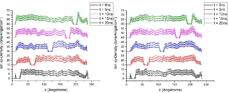
Figure 9. Planar ion density at diffe rent simulation times for porous piston simulations of (left) HA- and (right) DPA-functionalized INPs. Each density profile is averaged of 400 ps of simulation time, with error bars representing the standard deviation.
Although this data is encouraging as salt rejection is observed, there is again the problem of high variability in density values as noted by the error bars at each z value. Moreover, it cannot be clearly distinguished which ligand chemistry, HA or DPA, is more effective at salt rejection. For example, when observing the t = 10 ns data (blue line), it may appear that HA is more effective at salt rejection given the relatively higher peak directly in front of the INP membrane. However, when observing the t = 15 ns data (magenta line), one could reach the opposite conclusion that DPA is indeed more effective.
Furthermore, there is a technical problem to this simulation method that would be necessary to overcome if the results are truly to be trusted. The fact that the INP core coordinates are fixed and thus not allowed to move or rotate introduces a significant non-physical constraint on the system. It has been observed in previous MD filtration experiments where graphene boundaries are held fixed at atomistic distances that non-physical phenomena occur that could not be reproduced on a lab bench (Algara-Siller, Lehtinen et al. 2015). Thus, as the problem of free ion diffusion has been effectively solved and salt rejection was qualitatively observed, an issue of over-constraining the simulation parameters has presented itself.
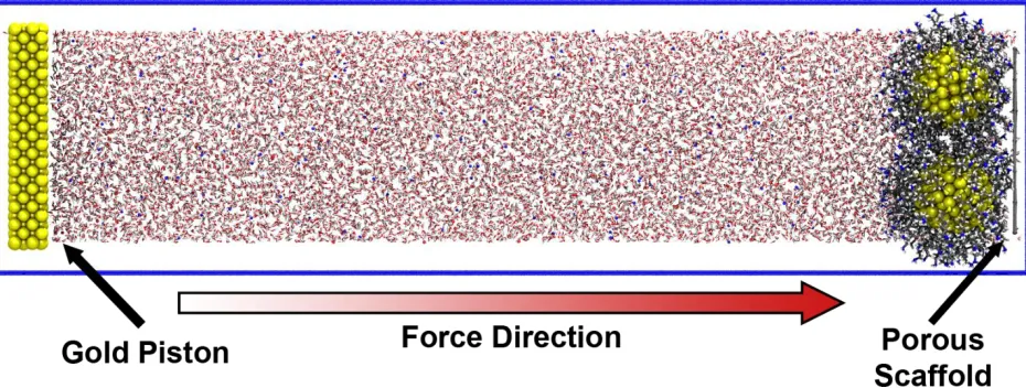
GOLD PIST ON – POR OUS SC AFF OL D
The following experimental setup is similar to a combination of the gold piston and porous piston solutions described above. Once again, 4 INPs from the compression simulations are used as starting coordinates and a piston composed of solid gold atoms is placed approximately 200 Å from the INP membrane. However, a porous scaffold of dummy atoms bonded on a square lattice is placed directly to the positive z side of the INP membrane. The porous scaffold is constructed similar to the porous piston in that experiment; the atoms have van der Waals parameters of an sp3
Figure 10. Simulation setup for HA-functionalized INPs with gold piston and fixed porous scaffold.
This was the last attempt at a filtration assay in the time allotted for this project. Unfortunately, the pressure increase caused by the gold piston on the INP membrane caused the system to become unstable during the filtration experiment. It could be that the scaffold is not porous enough to efficiently allow the water to flow around the INP membrane, thus creating a “clogged grate” effect. It is also possible that further changes in the INP membrane density (i.e. the distance between adjacent INPs) may be necessary to allow efficient water flow. However, at larger INP distances we have encountered similar sensitivity problems in planar ion density as shown above.
OUTREACH ACTIVI TIES
In our original proposal, we discussed outreach opportunities unique to simulation work in that simulations can be visualized in accessible and stimulating ways for general audiences. Some of this is evidenced by the schematics shown in the figures above. Although there is a large amount of physics and chemistry that goes into the development of the model, the resulting visualizations showing water, INPs, and a solid piston can be understood by general audiences. To this end, this research methodology has been summarized in an accessible manner in at video animation, that has recently been posted on our group YouTube channel at
https://www.youtube.com/watch?v=vPVQPwFe7vc&t=0s. The animation highlights the basic methodology of using simulations to investigate nanoparticles as a filtration mechanism for audiences at a wide variety of backgrounds.
CONCLUSIONS
At the conclusion of this project, we had limited success in developing an all atom MD assay that could sensitively predict salt rejection of functionalized INPs. Salt rejection was observed during non-equilibrium filtration assays. However, the large uncertainty associated with the accompanying data led to results that are macroscopically inconclusive.
Fortunately, our group entering the field of water purification has led to exciting collaborations for other remediation mechanisms. We have begun an initial partnership with RTI International to investigate directional solvents for desalination (see Figure 11). We have also performed preliminary simulations with Prof. Jan Genzer’s group here at North Carolina State University investigating materials for cyanide and phosphate removal.
We believe that direct collaboration with experimental researchers, such as in the projects described above, is a more efficient means of applying the computational techniques used by our group. Such collaborations allow a direct iterative approach between physical experiments and computational methodology in which progress in one arena
serves to inform the other. It is our belief that targeted collaborations such as these, made possible by this project, will provide us the most direct avenue to making a real impact on fresh water availability in North Carolina and beyond.