AT&T
AT&T SYSTEM 25
REFERENCE MANUAL
©1986 AT&T
All Rights Reserved Printed in USA
TO ORDER COPIES OF THIS DOCUMENT REFER TO DOCUMENT NUMBER 555-500-200.
Contact: Your AT&T Information Systems Account Team or
Call: 800-432-6600, Monday to Friday between 7:30 am and 6:00 EST, or
Write: AT&T Customer Information Center 2855 North Franklin Road
PO. Box 19901
FCC NOTIFICATION AND REPAIR INFORMATION AT&T SYSTEM 25
.
This telephone equipment is registered with the Federal Communications Commission in accordance with Part 68 of it’s Rules. In compliance with the Rules, be advised
(FCC) of the following:
MEANS OF CONNECTION
Connection of this telephone equipment to the nation-wide telecommunications network shall be through a standard network interface jack USOC RJ21X. Connection to private line network channels requires jack USOC RJ2GX for tie lines or jack USOC RJ21X for off-premises station lines. These can be ordered from your Telephone Company.
NOTIFICATION TO THE TELEPHONE COMPANY
If the system is to be connected to off-premises stations, you must notify the telephone company of the OPS class of service, 0L13C, and the service order code, 9. OF.
Upon the request of the telephone company, you shall inform them of the following
- The Public Switched Network “ lines” (that is, your phone number) and the Private “ lines” to which you will connect the telephone equipment.
- The telephone equipment’s “ registration number” and “ ringer equivalence number” (REN) from the label on the equipment.
- For Private Line Connections, provide the facility interface code; TL31M for tie lines. You must also specify the service order code, 9. OF.
- The quantities and USOC numbers of the jacks required.
- For each jack, provide the sequence in which lines are to be connected; the type lines and the facility interface code and the ringer equivalence number by position when applicable.
This telephone equipment should not be used on coin telephone lines. Connection to party line service is subject to state tariffs.
REPAIR INSTRUCTIONS
If you experience trouble with this telephone equipment, contact the AT&T Business Customer Service Center on 1-800-242-2121. The Telephone Company may ask that you disconnect this equipment from the network until the problem has been corrected or until you are sure that this equipment is not malfunctioning.
RIGHTS OF THE TELEPHONE COMPANY
Your Telephone Company may procedures that could affect the be notified in advance to give service.
make changes in it’s facilities, equipment, operations or proper functioning of your equipment. If they do, you will you an opportunity to maintain uninterrupted telephone
HEARING AID COMPATIBILITY
The voice terminals described in this manual are compatible with inductively coupled hearing aids as prescribed by the FCC.
I
FCC REGISTRATION INFORMATIONRegistration Number AS593M-71565-MF-E
Ringer Equivalence 0.5A
Network Interface RJ21X or RJ2GX
PRIVATE LINE SERVICE
Service Order Code
I
9.0F Facility Interface CodeFCC WARNING STATEMENT
Federal Communications Commission (FCC) Rules require that you be notified of the following:
● This equipment generates, uses, and can radiate radio frequency energy and, if not installed and used in accordance with the instruction manual, may cause interference to radio communications.
● It has been tested and found to comply with the limits for a Class A computing device pursuant to Subpart J of Part 15 of FCC Rules, which are designed to provide reasonable protection against such interference when operated in a commercial environment.
CONTENTS
A T T E N D A N T C O N S O L E 1. OVERVIEW
Organization
System 25 Overview Call Handling Capabilities Safety
System Configuration
2. FEATURES AND SERVICES I N T R O D U C T I O N
ACCOUNT CODE ENTRY ATTENDANT CALL TRANSFER A T T E N D A N T C A M P - O N A T T E N D A N T C A N C E L
Dual Attendant Console Operation
ATTENDANT DIRECT EXTENSION SELECTION ATTENDANT MESSAGE WAITING
ATTENDANT POSITION BUSY A T T E N D A N T R E L E A S E
ATTENDANT RETURN COVERAGE ON BUSY
ATTENDANT RETURN COVERAGE ON DON’T ANSWER ATTENDANT SPLITTING ONE-WAY AUTOMATIC A T T E N D A N T S Y S T E M A L A R M I N D I C A T I O N A U T O M A T I C I N T E R C O M
AUTOMATIC ROUTE SELECTION (ARS) C A L L A C C O U N T I N G S Y S T E M ( C A S ) C A L L C O V E R A G E – G R O U P C A L L C O V E R A G E – I N D I V I D U A L
C A L L F O L L O W I N G ( F O R W A R D I N G ) C A L L P A R K
C A L L P I C K U P
CALL PROGRESS TONES CALLING RESTRICTIONS
F a c i l i t y A c c e s s R e s t r i c t i o n : 2-50
A R S R e s t r i c t i o n : 2-50
COMMAND MODE AND DATA TERMINAL DIALING 2-52 D a t a T e r m i n a l D i a l i n g 2-54
C O N F E R E N C E 2-58
C O N F E R E N C E D R O P 2-60
D A T A C A L L S A N D S E R V I C E S 2-61
Data Endpoints 2-61
Data Endpoint States 2-63
Data Call Processing Modes 2-64
Connecting Configurations Controlling Features DIAL PLAN
DICTATION SYSTEM ACCESS DIRECT GROUP CALLING (DGC)
DIRECT GROUP CALLING DELAY ANNOUNCEMENT D I R E C T I N W A R D D I A L I N G ( D I D )
D I R E C T S T A T I O N S E L E C T I O N ( D S S ) D I S T I N C T I V E R I N G I N G
Abbreviated Alerting END-TO-END SIGNALING E X C L U S I O N
EXTENDED STATIONS EXTERNAL ALERTS
HANDS FREE ANSWER ON INTERCOM (HFAI) HOLD
HOLD RELEASE ON ABANDON
INTERCEPT TREATMENT WITH REORDER TONES INTERDIGIT TIMEOUTS
LINE SELECTION
L I N E S T A T U S A N D I - U S E I N D I C A T I O N S M A N U A L S I G N A L I N G
MESSAGING SERVICES Attendant Message Waiting: Call Coverage Message Waiting: Station-To-Station Message Waiting:
MUSIC-ON-HOLD OR DELAYED ACCESS N I G H T S E R V I C E .
NIGHT SERVICE DELAY ANNOUNCEMENTS O F F - P R E M I S E S S T A T I O N S ( O P S ) O N E - B U T T O N - T R A N S F E R T O D A T A O U T - O F - B U I L D I N G S T A T I O N S PAGING SYSTEM ACCESS
P A U S E
P E R S O N A L D I A L C O D E ( P D C ) P E R S O N A L L I N E S
POOLED FACILITY - BUTTON ACCESS POOLED FACILITY - DIAL ACCESS POWER FAILURE TRANSFER (PFT) P R O G R A M
R E C A L L
REMOTE ADMINISTRATION INTERFACE REPERTORY DIALING
S P E A K E R
S P E A K E R P H O N E A D J U N C T S P E E D D I A L I N G
S y s t e m S p e e d D i a l i n g : Personal Speed Dialing: S T A T I O N H U N T I N G
STATION MESSAGE DETAIL RECORDING (SMDR) C a l l A c c o u n t a b i l i t y :
STATION-TO-STATION MESSAGE WAITING T E S T
TIE TRUNKS
TOUCH-TONE AND DIAL PULSE SERVICES T R A N S F E R
TRUNK GROUPS
TRUNK-TO-TRUNK TRANSFER 3. FUNCTIONAL DESCRIPTION
TDM Bus P o r t C i r c u i t s
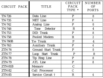
Ground Start Trunk (ZTN-76) Loop Start Trunk [ZTN-77) Tip Ring Line (ZTN-78) A T L L i n e ( Z T N - 7 9 ) Data Line (TN-726) MET Line (TN-735) Analog Line (TN-742) DID Trunk (TN-753) Tie Trunk (TN-760B) Auxiliary Trunk (TN-763) S y s t e m R e s o u r c e s Service Circuit (ZTN-85) Tone Detector (TN-748) Pooled Modem (TN-758) 4. HARDWARE DESCRIPTION
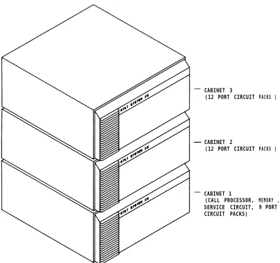
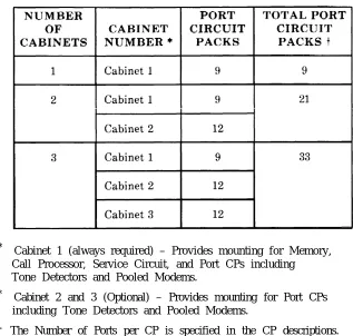
System Cabinets (J58901A1)
Cabinet l (Control and Port Circuits) C a b i n e t A d d r e s s P l u g
Cabinets 2 and 3 (Port Circuits) C i r c u i t P a c k s
Required Circuit Packs O p t i o n a l C i r c u i t P a c k s T e r m i n a l E q u i p m e n t
V o i c e T e r m i n a l s Voice Terminal Adjuncts A t t e n d a n t C o n s o l e s
Asynchronous Data Units (ADUs) P e r i p h e r a l E q u i p m e n t
S y s t e m A d m i n i s t r a t i o n T e r m i n a l D i g i t a l T a p e U n i t
Station Message Detail Recording (SMDR) And Call Accounting System (CAB)
Auxiliary Equipment
D i c t a t i o n E q u i p m e n t
Music Source (Music-On-Hold) P a g i n g E q u i p m e n t
Recorded Delay Announcement Equipment C o n n e c t i v i t y
Trunk Access Equipment (TAE) Station Interconnect Panel (SIP) 10B Emergency Transfer Unit (ETU) Connectivity Figures
Voice Terminal And Adjunct Connections Attendant Console Connections Peripheral Equipment Connections ADU Connections Auxiliary Equipment Connections P a r t s I n f o r m a t i o n
5. SOFTWARE DESCRIPTION G e n e r a l
Switched Services Software Administrative Software Maintenance Software Memory Allocation Real-Time Constraints Software Partitioning Step-By-Step Call Description 6. SYSTEM ADMINISTRATION 7. SYSTEM MAINTENANCE System Errors And Alarms Error Logs Automatic Maintenance Tests 8. TECHNICAL SPECIFICATIONS
Hardware And Software Parameters Unit Loads Cable Distance Limitations T o n e s
Indicator Lamp Signals
9. ENVIRONMENTAL REQUIREMENTS 9-1 Floor Plans And Layouts 9-1 Table Top Space 9-4 Wall Space Requirements 9-4 Temperature and Humidity 9-4 Air Purity 9-5 Lighting 9-5 Electrical Noise (RFI) 9-5 AC Power Requirements 9-6 Grounding 9-8 Lightning Protection 9-8 10. REFERENCE DOCUMENTATION 10-1 Administration Manual (555-500-500) 10-1 An Introduction to AT&T System 25 (555-500-021) 10-1 Implementation Manual (555-500-650) 10-2 Installation And Test Manual (555-500-100) 10-2 Maintenance Manual (555-500-105) 10-2 Planning Manual (555-500-600) 10-2 Reference Manual (555-500-200) 10-2 Terminal Operations Manual (555-500-710) 10-3 User Guides (700 Series) 10-3 11. GLOSSARY 11-1 12.INDEX 12-1
Figure 1-l Figure 2-1 Figure 2-2 Figure 2-3 Figure 2-4 Figure 2-5 Figure 2-6 Figure 3-1 Figure 3-2 Figure 3-3 Figure 3-4 Figure 3-5 Figure 3-6 Figure 3-7 Figure 3-8 Figure 3-9 Figure 3-10 Figure 3-11 Figure 3-12
LIST OF FIGURES
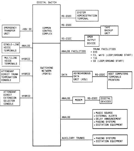
System 25 Block Diagram
Automatic Route Selection Flow Chart (Sheet l of 2) Automatic Route Selection Routing Pattern Asynchronous Data Unit Interface Signals Typical SMDRCall Detail Report SMDR Call Record Format SMDR Call Record Header Format
System 25 Digital Switch Call Processor (ZTN-82) Circuitry Memory (ZTN-8113) Circuitry TDM Bus Time Slot Generation (Not A Timing Diagram)
TDM Bus Diagram - T h r e e C a b i n e t S y s t e m
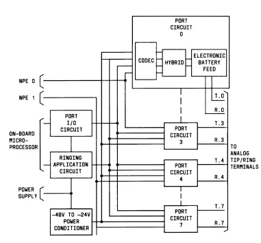
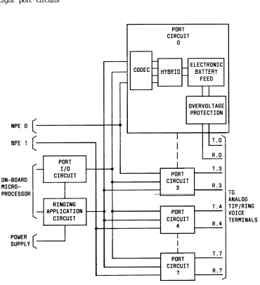
Equipment Connected To System 25 Via The Call Processor And Port C i r c u i t P a c k s ( S h e e t l o f 3 )
Port Circuit Pack Common Circuitry Unique Ground Start Trunk (ZTN-76) Circuitry Unique Loop Start Trunk (ZTN-77) Circuitry Unique Tip Ring Line (ZTN-78) Circuitry U n i q u e A T L L i n e ( Z T N - 7 9 ) C i r c u i t r y U n i q u e D a t a L i n e ( T N - 7 2 6 ) C i r c u i t r y F i g u r e 3 - 1 3 U n i q u e M E T L i n e ( T N - 7 3 5 ) C i r c u i t r y Figure 3-14 Unique Analog Line (TN-742) Circuitry Figure 3-15 Unique DID Trunk (TN-753) Circuitry F i g u r e 3 - 1 6 U n i q u e T i e T r u n k ( T N - 7 6 0 B ) C i r c u i t r y Figure 3-17 Tie Trunk (TN-760B) Circuit Pack Option Switches Figure 3-18 Unique Auxiliary Trunk (TN-763) Circuitry Figure 3-19 Service Circuit (ZTN-85)
F i g u r e 3 - 2 0 T o n e D e t e c t o r ( T N - 7 4 8 ) C i r c u i t Figure 3-21 Pooled Modem (TN-758) Circuit
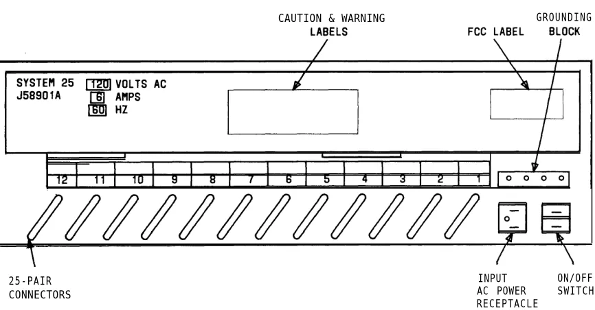
Figure 4-1 System 25 Cabinets (J58901A)–Three Cabinet System F i g u r e 4 - 2 S y s t e m C a b i n e t ( J 5 8 9 0 1 A ) — R e a r V i e w
Figure 4-5 Figure 4-6 Figure 4-7 Figure 4-8 Figure 4-9 Figure 4-10 Figure 4-11 Figure 4-12 Figure 4-13 Figure 4-14 Figure 4-15 Figure 4-16 Figure 4-17 Figure 4-18 Figure 4-19 Figure 4-20 Figure 4-21 Figure 4-22 Figure 4-23 Figure 4-24 Figure 4-25 Figure 4-26 Figure 4-27 Figure 4-28 Figure 4-29 Figure 4-30 Figure 4-31 Figure 4-32 Figure 4-33 Figure 4-34 Figure 4-35 Figure 4-36
M o d e 1 7 1 0 1 A ( A n a l o g ) V o i c e T e r m i n a l F i v e B u t t o n V o i c e T e r m i n a l ( 7 3 0 2 H O l C ) T e n B u t t o n V o i c e T e r m i n a l ( 7 3 0 3 H O l B ) 3 4 - B u t t o n V o i c e T e r m i n a l ( 7 3 0 5 H O l B ) 34-Button Deluxe Voice Terminal (7305H02B) B I S V o i c e T e r m i n a l ( 7 3 0 5 H 0 3 B )
HFAI Voice Terminal (7309HOlA) T e n B u t t o n M E T S e t ( 2 9 9 1 C 0 5 )
Ten Button MET With Built-In Speakerphone (2993C04) T w e l v e B u t t o n M E T S e t ( 7 2 0 3 M )
5 0 0 A / 5 0 2 A H e a d s e t A d a p t e r s 4 A S p e a k e r p h o n e S y s t e m S 1 0 1 A / S 1 0 2 A S p e a k e r p h o n e Attendant Consoles
Model 23A1 Attendant Direct Extension Selector (DXS)
Asynchronous Data Unit (ADU)
Model 703 System Administration Terminal M o d e l D C 5 D i g i t a l T a p e U n i t
T r u n k A c c e s s E q u i p m e n t ( T A E ) C o n n e c t i o n s 6 1 7 A S t a t i o n I n t e r c o n n e c t P a n e l
T y p i c a l S I P C o n n e c t i o n s 10B Emergency Transfer Unit (ETU)
Emergency Transfer Unit Connections M u l t i p l e E T U A r r a n g e m e n t s
On-Premises Single-Line Voice Terminal Connections Out-Of-Building Single-Line Voice Terminal Connections Off-Premises Station Single-Line Voice Terminal Connections
On-Premises 7300H Series Multiline Voice Terminal C o n n e c t i o n s
Out-Of-Building 7300H Series Multiline Voice Terminal Connections
Typical Adjunct Connections For 7300H Series Multiline Voice Terminals (Except 34-Button Deluxe Set)
Typical Adjunct Connections For 34-Button (Includes Attendant Direct Trunk Console)
Deluxe Voice Terminal
Figure 4-38 Figure 4-39 Figure 4-40 Figure 4-41 Figure 4-42 Figure 4-43 Figure 4-44 Figure 4-45 Figure 4-46 Figure 4-47 Figure 4-48 Figure 4-49 Figure 4-50 Figure 4-51 Figure 4-52 Figure 4-53 Figure 4-54 Figure 5-1 Figure 8-1 Figure 8-2 Figure 8-3 Figure 9-1 Figure 9-2 Figure 9-3
Attendant Direct Trunk Console Connections
A t t e n d a n t D i r e c t E x t e n s i o n S e l e c t o r C o n s o l e C o n n e c t i o n s Typical Peripheral Equipment– On-Premises Direct Connections (Sharing Same AC Outlet)
Typical Peripheral Equipment–On-Premises Direct Connections (Greater Than 50 Feet From System Cabinet)
Typical Peripheral Equipment–On-Premises Switched Connections
Typical Peripheral Equipment—Off-Premises Direct Connections
Typical Peripheral Equipment–Off-Premises Switched Connections
Typical ADU Connections– Supporting Data Terminal And Single-Line Voice Terminal
Typical ADU Connections–Supporting Data Terminal And 7300H S e r i e s M u l t i l i n e V o i c e T e r m i n a l
Z 3 A 1 / 2 / 4 A D U L o c a l P o w e r C o n n e c t i o n s
D i c t a t i o n S y s t e m C o n n e c t i o n s ( F C C R e g i s t e r e d ) E x t e r n a l A l e r t C o n n e c t i o n s
Music-On-Hold Equipment Connections (FCC Registered) Music-On-Hold Equipment Connections (Non-Registered) Paging Equipment Connections—Using CO Trunk Ports (FCC R e g i s t e r e d )
Paging Equipment Connections— Using Auxiliary Trunk Ports (FCC Registered Or Non-Registered)
Delay Announcement Equipment Connections (FCC R e g i s t e r e d )
System Software Partitioning
Single-Line Voice Terminal Allowable Cable Distances Multiline Voice Terminal Allowable Cable Distances A s y n c h r o n o u s D a t a U n i t A l l o w a b l e C a b l e D i s t a n c e s T y p i c a l S y s t e m 2 5 E q u i p m e n t A r e a F l o o r P l a n Typical System 25 Equipment Area Elevation Plan AC Power Distribution - Multiple Cabinet System
LIST OF TABLES TABLE 2-A TABLE 2-B TABLE 2-C TABLE 2-D TABLE 2-E TABLE 2-F TABLE 3-A TABLE 3-B TABLE 3-C TABLE 3-D TABLE 4-A TABLE 4-B TABLE 4-C TABLE 4-D TABLE 8-A
S y s t e m F e a t u r e s Station Features Attendant Features D a t a F e a t u r e s
Permissible Data Port (TN-726) Options
Call Progress Messages for Data Terminal Dialing T D M B U S T i m e S l o t s
TN-760B Available Signaling Formats
TN-760B Tie Trunk Preferred Signaling Formats S i g n a l i n g T y p e S u m m a r y
Total Port Circuit Packs Per System S y s t e m C i r c u i t P a c k s
Supplemental Voice Terminal Power Supplies Z3A Asynchronous Data Units (ADUs) Central Office Trunk Recommendations
1. OVERVIEW
This manual provides general technical information on AT&T System 25 (System 25). It includes a description of the system, its hardware and software, features and services, environmental requirements, and technical specifications. This manual is intended to serve as an overall technical reference for System 25.
Organization
The manual is divided into 12 Sections. The remaining Sections are as follows: ● SECTION 2–FEATURES AND SERVICES
● SECTION 3–FUNCTIONAL DESCRIPTION ● SECTION 4–HARDWARE DESCRIPTION ● SECTION 5–SOFTWARE DESCRIPTION ● SECTION 6–SYSTEM ADMINISTRATION ● SECTION 7–SYSTEM MAINTENANCE ● SECTION 8–TECHNICAL SPECIFICATIONS
● SECTION 9–ENVIRONMENTAL REQUIREMENTS ● SECTION 10–REFERENCE DOCUMENTATION ● SECTION 11–GLOSSARY
System 25 Overview
S y s t e m 2 5 is a n a d v a n c e d d i g i t a l s w i t c h i n g s y s t e m w h i c h i n t e g r a t e s v o i c e a n d d a t a communications. It not only provides the features of a state-of-the-art PBX, but goes a step further by allowing digital data to be switched point-to-point without first being converted to analog format. This capability can be used to set up connections between data terminals, word processors, personal computers, and host computers.
S y s t e m 25 uses intelligent port circuits equipped with distributed network processor elements to provide (essentially) nonblocking voice and data switching.
Voice communications features combine traditional telephone features, such as Call Transfer and Hold, with advanced features, such as Individual and Group Call Coverage, Hands-Free-Answer On Intercom, and Speed Dialing (See “Features and Services’’ -Section 2.)
Data communications features provide switched data connections supporting transmission of voice or data over Premises Distribution System wiring. Connections can be made between two digital data modules (asynchronous data units), two analog modems, or between an analog modem and a digital data module.
The system provides an RS-232C interface for full duplex, asynchronous, transmission of data up to 19,200 bps, and a 212-compatible modem pool conversion resource.
System 25 supports the following:
● Trunk and Network Facilities–Dual Tone Multifrequency (DTMF) and Dial Pulse Signaling on incoming and outgoing trunks (dial pulse only on DID trunks).
— Loop Start (LS)
— Ground Start (GS)–(Strongly preferred Over Loop start)
— Tie Trunks (Type I and Type I Compatible E&M, Type V Simplex) – Direct Inward Dialing (DID)
● Voice Terminals–Single-Line Touch-Tone, MET, and MERLIN® ● Data Facilities
— Digital Data End Points—RS-232C Interfaces via Asynchronous Data Units (ADUs)
— Analog Data End Points—Tip/Ring-Type Modem Interfaces, ● Networking Capability
— Tie Trunks
— Endpoint in Electronic Tandem Network–(Tributary only, not Satellite) — Endpoint of Enhanced Private Switched Communications Services (EPSCS) — Endpoint of Tandem Tie Trunk Network (TTTN)
Call Handling Capabilities
System 25 can be arranged as a stand-alone system or can be part of a private network. The system provides 256 ports to support the following:
● 115 simultaneous two-party conversations
● Traffic Handling–4140 CCS/Hour (Trunking Limited)
● Busy Hour Call Capacity–2500 calls (DTMF Register Limited)
● Up to 104 trunk ports including Central Office (CO), DID, Tie, Foreign Exchange (FX), and Wide Area Telecommunications Service (WATS), and 800 Service.
● An Auxiliary Trunk interface for paging and dictation systems ● Up to 240 ports that support a combination of the following:
— Up to 200 ports for voice terminals and auxiliary equipment.
— Up to 104 data ports providing RS-232C connections to data terminals, personal or multiport computers.
Refer to Hardware and Software Parameters as provided in “Technical Specifications” (Section 8) for detailed specifications.
Safety
System 25 meets all requirements found in Underwriters Laboratories Standard for Safety, Office Appliances and Business Equipment (UL114).
System Configuration
1 J
2. FEATURES AND SERVICES
INTRODUCTION
This section describes the System Features, Station Features, Attendant Features, and Data Features of AT&T System 25. The feature descriptions are arranged in alphabetical order, regardless of the feature group to which they belong. Information for each feature is presented under five headings: Description, Considerations, Interactions, Administration, and Hardware Requirements.
● Description
Defines the feature, describes what it does for the user, and how it is used. ● Considerations
Discusses the applications a n d b e n e f i t s o f t h e f e a t u r e , f o l l o w e d b y f e a t u r e parameters and factors to reconsidered when the feature is used.
● Interactions
Lists and briefly describes other features that may affect the feature being described. Interacting features are those that:
— Depend on each other—One of the features must be provided if the other one is.
— Cannot coexist—One of the features cannot be provided if the other one is. — Affect each other–The operation of one feature modifies, or is modified by,
the operation of the other.
— Enhance each other—The features, in combination, provide improved service to the user.
● Administration
S t a t e s w h e t h e r o r n o t a d m i n i s t r a t i o n i s r e q u i r e d a n d l i s t s i t e m s r e q u i r i n g administration.
● Hardware Requirements
List any additional hardware needed to use the feature.
A listing of features by group (System, Station, Attendant or Data) immediately follows this Introduction. Each feature’s type is also noted on this list. Features are either:
● ●
●
Standard features–Built into each system (always provided).
Custom features–Require administration (inputting feature related parameters via the System Administration Terminal).
Features restricted to single-line or multiline voice terminals are noted where applicable. MET sets operate the same way as 5-button 7300H series voice terminals, unless otherwise noted.
System Features
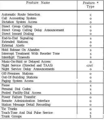
System features (Table 2-A) are those that affect the entire system’s operation.
TABLE 2-A. System Features
Feature Name Feature *
Type
Automatic Route Selection c
Call Accounting System o
Dictation System Access o
Direct Group Calling c
Direct Group Calling Delay Announcement o
Direct Inward Dialing o
End-to-End Signaling s
Extended Stations o
External Alerts o
Hold Release On Abandon s
Intercept Treatment With Reorder Tone s
Interdigit Timeouts s
Music-On-Hold or Delayed Access o Night Service (Directed and TAAS) c / o † Night Service Delay Announcements o
Off-Premises Stations o
Out-Of-Building Stations o
Paging System Access I o
Pause s
Personal Dial Codes s
Pooled Facility-Dial Access s
Power Failure Transfer o
Remote Administration Interface o Station Message Detail Recording o
Tie Trunks o
Touch-Tone And Dial Pulse Service s
Trunk Groups
I
s
I
* Feature types are: S= Standard, C= Custom, O= Optional.
Custom features require administration, Optional features require administration and additional equipment.
Station Features
The many Station Features (Table 2-B) available allow individual needs to be met. As these needs change, assigned features can also be changed. Station Features provide many 2
important services that help save time and make calling more convenient.
T A B L E 2 - B . S t a t i o n F e a t u r e s
F e a t u r e N a m e S i n g l e - L i n e M u l t i l i n e F e a t u r e V o i c e T e r m i n a l V o i c e T e r m i n a l ‡ Type *
Account Code Entry x [ACCT ENTRY] s/c †
Automatic Intercom [AUTO ICOM] c
Call Coverage-Group x [COVER-GRP] c
Call Coverage-Individual x [COVER-IND] c
Call Following (Forwarding) x x s
Call Park x x s
Call Pickup x x s
Calling Restrictions x x c
Conference x x s
Conference Drop x x s
Direct Station Selection (DSS) [DSS or FLEX DSS] c
Distinctive Ringing x x s
Exclusion [EXCLUSION] c
Hands-Free-Answer On Intercom [AUTO ANS] o
Hold x x s
Line Selection x s
Line Status And I-Use Indications x s
Manual Signaling [SIGNAL] c
Messaging Services x x s
Personal Lines [PERS LINE] c
Pooled Facility-Button Access [FACILITY] c
Program x x s
Recall x x s
Repertory Dialing [REP DIAL] c
Speaker (Spokesman Service ) x s
Speakerphone Adjunct x x o
Speed Dialing x x S / C †
Station Hunting x c
Station-To-Station Message Waiting [MSG WAIT] c
Test x s
Transfer x x s
Trunk-To-Trunk Transfer x x s
Attendant Features
Attendant Features (Table 2-C) are available to the attendant using the Direct Trunk Console and (optionally) a Direct Extension Selector (DXS) Console. In addition, all
multiline voice terminal station features are available to the attendant.
2
TABLE 2-C. Attendant Features
Feature Name
Attendant Call Transfer Attendant Camp-on Attendant Cancel
Attendant Direct Extension Selection Attendant Message Waiting
Attendant Position Busy Attendant Release
Attendant Return Coverage on Busy.
Attendant Return Coverage on Don’t Answer Attendant Splitting One-Way Automatic Attendant System Alarm Indication Night Service
Console Button Feature Label ‡ Type *
[START] [CANCEL] [ATT MSG] [POS BUSY1 s s s o s c [RELEASE] s [RTN-BUSY] s (RTN-DA) s s [ALARM] s (NIGHT1 c Data Features
Data Features (Table 2-D) provide switched connections
support the system’s switched data services. Data services between analog and digital data endpoints.
TABLE 2-D. Data Features
Feature Name
Command Mode Data Terminal Dialing Modem Pooling
One-Button-Transfer to Data
Multiline Terminal Feature Button Label ‡ Type *
[DATA]
s s o c
* Feature types are S= Standard, C= Custom, O= Optional.
Custom features require administration, Optional features require administration and additional equipment.
ACCOUNT CODE ENTRY
Description
2
Allows voice terminal users to associate an account code with incoming and outgoing calls. This is accomplished by entering the account code at the voice terminal before hanging up. The account code is appended to the SMDR call record and can be used later for accounting or billing purposes.To associate an account code with a call, the user, after completing a call but before hanging up, must:
● Single-Line Voice Terminal User:
- Flash the switchhook, dial *O, and then dial the account code directly or dial a System or Personal Speed Dial Number that contains the account code.
● Multilane Voice Terminal User:
- Press Account Code Entry (ACCT ENTRY) button and then dial the account code directly or dial a System or Personal Speed Dial Number that contains the account code. A Repertory Dial (REP DIAL) button may also be used to enter an account code.
● When the correct number of account code digits have been entered, Confirmation Tone followed by Dial Tone is returned to the user and the account code is appended to the SMDR call record.
Account Code Entry is optional.
Considerations
Account Code Entry provides an easy method of allocating the costs of specific calls (and associated staff time) to the correct project, department or user. The account code is appended to the SMDR call record and sent to the SMDR output channel.
Account Codes can include up to 15 digits.
The validity of the entered account code is not checked by the system.
If the user is active on a call, invoking the featyure will dropthe call.
Incorrectly dialed codes (prior to last digit entry) may be corrected via a second switchhook flash or pressing ACCT ENTRY and reentering the code. Partial account codes entered by going on-hook before completing entry are recorded and cannot be corrected.
If, before all digits have been entered, (1) the user goes on-hook, (2) a button other than ACCT ENTRY is pressed, or (3) 30 seconds have elapsed since the feature was invoked, the SMDR call record will show the digits dialed up to that point.
Interactions
● Conference: If more than one user attempts to enter an account code on a Conference Call, the first to enter a code will prevail.
● Repertory Dialing: An Account Code may be stored on a REP DIAL button. Press REP DIAL at the point where ACCT ENTRY would normally be pressed.
● Speed Dialing: An Account code may be stored in System or Personal Speed Dial Number.
● Transfer: A user may transfer a call to another user, then, instead of hanging up, enter an account code. Subsequent account code entries for the same call will be ignored.
Administration System:
● Maximum number of Account Code digits (0-15)--Default = 15. Voice Terminal: (Station Port)
● Multiline terminals–Account Code Entry Button is required. ● Single-line terminals—none.
Hardware Requirements
ATTENDANT CALL TRANSFER
Description
Allows the attendant to transfer an incoming call using the Attendant Console START and RELEASE buttons or the (optional) DXS console.
While the Attendant Console has a button labeled TRANSFER, this button invokes the standard multiline voice terminal Transfer feature and should not be used by the attendant to extend incoming calls. The Attendant Call Transfer feature described below should be used for this purpose.
To extend an incoming call, the attendant, after answering the call can either:
1. Press START which places the incoming call on hold via the Attendant Splitting One-Way Automatic feature. After receiving Dial Tone, the attendant then dials the requested extension
or
2. Press the DXS Console button associated with the requested station. This operation is equivalent to pressing START and dialing the extension.
If ringing tone is heard, the attendant either presses (1) RELEASE (Manual Release) or (2) a n y f a c i l i t y b u t t o n s u c h a s S y s t e m A c c e s s , A u t o m a t i c I n t e r c o m , o r a n o u t s i d e l i n e (Attendant Automatic Release) to complete the transfer.
If busy tone is heard and Attendant Camp-On (see associated feature description) is not desired, the attendant presses CANCEL and is reconnected to the calling party.
If Busy Tone is heard and Attendant Camp-On is desired, the attendant presses RELEASE or any facility button. The called party hears a tone burst and the call is held at the called voice terminal. When a busy single-line station goes on-hook, or a busy multiline station System Access button becomes idle, the call automatically begins ringing at the station. Only one Camped-On call is permitted per voice terminal.
Calls extended to an idle voice terminal that are not answered within a specified time return to the Attendant Console on the Return-On-Don’t-Answer (RTN-DA) button. Calls camped-on at a busy voice terminal that are not answered within a specified time return to the Attendant Console on the Return-On-Busy (RTN-BUSY) button. If these buttons are busy on another call, the extended call remains at the called terminal until that button becomes idle.
Considerations
Interactions
Refer to the following feature definitions for additional feature related information:
● A t t e n d a n t ● Attendant ● Attendant ● A t t e n d a n t ● Attendant ● Attendant
Administration System:
Camp-On
Direct Extension Selection Release
Return Coverage On Busy
Return Coverage On Don’t Answer Splitting One-Way Automatic.
● Number of seconds before a Camped-On call returns to the Attendant Console (1-120 seconds), or No Attendant Camp-On (0) - Default = 30 seconds
● Number of rings before unanswered call returns to the Attendant Console (1-31) - Default = 5.
ATTENDANT CAMP-ON
Description
Allows the attendant to extend an outside call to a busy single-line voice terminal or a multiline voice terminal active on both System Access buttons. When the attendant releases from the call, a burst of tone is heard at the called terminal. The caller is placed on hold and hears music-on-hold, if available. When a System Access button becomes idle or the single-line terminal hangs up, the held call is connected automatically and ringing begins. Only one call may be camped-on to a voice terminal. This feature is referred to as a “Waiting Call” in the User Guides (555-500-700 series).
Note: Only outside calls can receive Camp-On service. If the attendant provides coverage for a station whose incoming call has been redirected to the attendant, the call is considered an inside call and can not be given camp-on service.
Considerations
A camped-on call can be answered by a busy single-line user without losing the current call by momentarily pressing the switchhook (which places the current call on hold) and then dialing *9. Multiline terminal users cannot do this. However, if they have a System Access-Originate button they can place both calls on hold, go off-hook on that button and dial *9 to pick up the camped-on call.
If the camped-on call is not answered within a specified time, the call will be returned to the Attendant-
Console Return-On-Busy (RTN-BUSY) button. If that button is busy, the call remains camped-on until the button becomes idle.
Interactions
● Call Coverage/Direct Group Calling: If the called party is a member of a hunt (DGC or Call Coverage) group and all members of the group, or all receivers of the Coverage group are busy, the call will not hunt or receive coverage. Once camped-on, calls will no longer hunt or receive coverage even if the hunted-to station or group member becomes idle.
● Direct Group Calling: The attendant can camp-on one call per DGC group. Voice terminals in the group do not receive a burst of tone when a call is camped on. If the attendant attempts to camp-on a second call, it is immediately returned on the RTN-BUSY button.
● Direct Inward Dialing: DID calls may be covered by the attendant and then given Camp-On treatment. They do not automatically receive Call Waiting.
Administration System:
● Number of seconds before a camped-on call returns to the Attendant Console (1-120 seconds) or No Attendant Camp-On allowed (0) - Default = 30 seconds.
ATTENDANT CANCEL
Description
Allows the attendant to terminate an attempt to extend any incoming call if the called station does not answer or if the station answers but declines to accept the call. Before pressing RELEASE, the attendant presses CANCEL and is automatically reconnected to the calling party.
Pressing CANCEL when the Start facility is not active will be ignored.
Considerations
Attendant Cancel allows the attendant to terminate a call transfer attempt and return to the incoming held party via a one-button operation. This enhances the attendant’s ability to handle calls quickly and efficiently.
Interactions None
Administration None Required
ATTENDANT CONSOLE
The Attendant Direct Trunk Console (Attendant Console) is used to facilitate the completion of incoming calls, place outgoing calls, and manage and monitor some of the system’s operation. Special attendant related features simplify inward call transfer and the servicing of unanswered calls. Each system may be equipped with up to two Attendant Consoles (Primary and Secondary) which can operate simultaneously. The Attendant Console is a 34-button deluxe console; all standard multiline voice terminal features are also available to the attendant.
Each attendant may also have an associated Attendant Direct Extension Selector (DXS) Console. The DXS Console operation is described in the “Attendant Direct Extension Selection” feature description.
Unique feature buttons and associated status LEDs on the Attendant Console are:
● Start [START] Initiates an inward call transfer by placing a caller on-hold and provides internal dial tone to the attendant
● Cancel [CANCEL] Terminates the “Start” operation and reconnects the attendant to the calling party.
● Release [RELEASE] Releases the attendant from an active call. When used on a call that the attendant is in the process of extending, Release completes the transfer.
● Return-On-Busy [RTN-BUSY} Calls extended to a busy station are returned to the console if not answered within a specified interval.
● Return-On-Don’t-Answer [RTN-DA} Extended calls not answered are returned to the console if not answered within a specified interval.
● Position Busy [POS BUSY]: In a dual attendant console system, Position Busy removes an Attendant Console from service. Only one of two consoles can be in the “Position Busy” mode at a time.
● Night Service [NIGHT]: Used to activate/deactivate the Night Service feature. ● Attendant Message Waiting [ATT MSG] Used by the attendant to turn On or
Off Message LEDs on voice terminals so equipped.
If the system has two Attendant Consoles, one console is considered to be the primary console and the other the secondary console.
Dual Attendant Console Operation
The following calls will be routed to the primary console. If the primary attendant has activated the Position Busy feature or is busy on both System Access buttons, these calls will be routed to the secondary console. If that console is also busy on both System Access buttons, busy tone is provided to the calling party. The call types are:
● Dial “0” calls
● DID calls to unassigned numbers (when administered to route to the attendant) ● Calls to Floating PDCs (FPDCs) not logged in (when administered to route to the
attendant)
● Calls on incoming facilities that terminate on that console.
System users and DID callers may reach a particular attendant by dialing that attendant’s PDC.
A POS BUSY button can be assigned to each console; this permits selection of one of two modes of operation: (1) simultaneous operation or (2) only one Attendant Console active. However, only one console is allowed to be inactive at any given time. An associated POS BUSY status LED is lighted when the console is inactive. Ringing is disabled on all trunk terminations on the busy console’s rightmost two columns of buttons. Ringers disabled on a busy console will be enabled on the active console for those trunks with dual appearances (appearances on both consoles). All other features on all buttons, including those on the associated Attendant Direct Extension Selector (DXS) Console will continue to function normally even though the console is inactive.
The Attendant Position Busy feature description provides additional information.
Administration System:
● Assign Primary and Secondary Attendant Positions
● Assign number of rings before unanswered calls return to the Attendant Position (1-31) - Default = 5 rings
● Send DID calls to unassigned numbers to the Attendant Position (Yes, No) - Default = Yes
● Send calls to Floating Personal Dial Codes that are not logged-in to the Attendant Position (Yes, No) - Default = Yes
Attendant Console: (Station Port) ● Special Programmable Buttons:
— Night Service Position Busy
— Attendant Message Waiting (assigned by default).
NOTE: The following buttons or LEDs are predefined on the Attendant Console and are not administrable:
— Alarm (LED)
— Return-On-Don’t-Answer — Return-On-Busy
— S t a r t — Cancel — Release
● Trunk terminations—The following is required for each trunk terminated on the console (administered as Personal Line appearances):
— Trunk Number
ATTENDANT DIRECT EXTENSION SELECTION
Description
Permits the attendant to extend calls to stations by pressing a single button pressing START and dialing the PDC or DDC. The primary and secondary Consoles each may have an associated Direct Extension Selector (DXS) Console.
instead of A t t e n d a n t
The DXS Console has an array of 100 DXS buttons plus seven Group Select buttons. Pressing a Group Select button causes the DXS buttons to be associated with PDCs from an associated hundreds group. Default assignments for the Group Select buttons are 200-299, 300-399, etc., up to 800-899. Group Select buttons can be assigned any hundreds group in the dialing plan.
Pressing a DXS button when off-hook on an incoming call is equivalent to pressing START and dialing a station. Such action will busy out the Start facility until the call is released. When the attendant is already active on the START button, the system will ignore a DXS button press.
The DXS LED associated with a particular station will flash when: (1) a station calls the attendant, (2) a call extended to a station returns on the Return-On-Busy (RTN-BUSY) or Return-On-Don’t-Answer (RTN-DA) buttons, (3) an extended call is directed to a Cover button on the Attendant Console. The LED stops flashing when the call is answered. On Return-On-Busy or Return-On-Don’t-Answer calls the LED status will return to the state t h a t r e f l e c t s t h e s t a t i o n s c u r r e n t b u s y / i d l e s t a t u s w h e n t h e c a l l i s a n s w e r e d b y t h e attendant.
An outside call may be parked via the DXS Console by pressing one of the eight Call Park buttons that may be programmed on the Console. On the Attendant Console, the facility status LED of the parked call winks (to indicate that the call is held) and the status LED on the DXS Console lights steadily.
A call parked via the DXS Console and not picked up within two minutes will return to the RTN-DA button.
A call parked via the DXS Console may be picked up at any voice terminal by dialing the Call Park retrieval code (*8) and the number of the DXS button used to park the call.
The rightmost button on the bottom of the console is a Test button. When it is pressed, all DXS LEDs will light sequentially; a second press allows individual LEDs to be tested and a third press ends the test.
Dual Attendant DXS Consoles
Considerations
Buttons on the DXS Console point to either station PDCs or floating PDCs (FPDCs). Calls extended by the DXS console are directed as described in the “Personal Dial Codes” feature description.
When a station calls the attendant, the associated LED on the DXS Console will flash while the call is ringing and will light steadily when the attendant answers the call. The LED will light steadily whenever the terminal is off-hook. Station busy indication is not provided for buttons pointing to floating PDCs (FPDCs).
If a call to a PDC is directed to a Cover button on the Attendant Console, the covered voice terminal’s status LED on the DXS Console will flash and then light steadily when the call is answered by the attendant. If the covered call was intended for a FPDC which was logged in at a terminal with attendant coverage, the DXS Console status LED associated with the FPDC (if assigned) will not light. In this case, just the Cover button status LED will light. A call may arrive at an Attendant Console System Access button because the PDC or FPDC is logged in at the Console
or
because the FPDC is not logged in. For these calls, the status LED on the DXS Console will not light.If the attendant extends a call to a station and that call returns to the attendant, then the station’s status LED on the DXS Console will flash and then light steadily when the call is answered by the attendant. This is true regardless of the login status of the PDC. If the attendant extends a call to a FPDC and that call returns to the attendant then the FPDC status LED on the DXS Console will not light.
Interactions
●
●
●
●
Attendant Position Busy: The DXS Console functions normally when the associated Attendant Direct Trunk Console is in the inactive mode.
Attendant Return Coverage On Busy/Or Don’t Answer: If a call to a FPDC is returned to the attendant on a RTN-BUSY or RTN-DA button, the FPDCs status LED on the DXS Console will flash during ringing and light steadily when answered.
Call Coverage: If the attendant receives a coverage call for a FPDC, the associated status LED on the DXS Console will not light. .
Direct Extension Selection: When all stations is a DGC group are busy, the status LED on the DXS Console lights.
Administration Special Feature Ports:
● Assign Group Select button hundreds groups and Call Park codes.
● Requires a port assignment on a ZTN-79 ATL Line Circuit Pack (CP) for each DXS Console.
Hardware Requirements
ATTENDANT MESSAGE WAITING
Description
Allows the attendant to control the status of Message LEDs on stations so equipped.
Considerations
This feature allows the attendant to notify stations that a message is available for them. The attendant can activate the station’s Message LED while either (1) ringing, (2) receiving Busy Tone, or (3) talking to a station. The status of the called party’s Message LED is reflected by the Attendant Message Waiting (ATT MSG) status LED in any of these cases. To activate (light) a user’s Message LED in any of these cases, the attendant presses the ATT MSG button. If the voice terminal is not equipped with a Message LED, the attendant’s LED will remain dark.
If the attendant presses ATT MSG a second (or third) time before hanging up, the user’s Message LED will turn Off’(and back On), etc.
The red I-Use LED associated with the ATT MSG button does not light.
The attendant can turn On or turn Off a user’s Message LED without disturbing the user by going off-hook on a System Access button, pressing ATT MSG to obtain the required state, and then dialing the station. Confirmation Tone is returned.
This feature is not the same as the Station-To-Station Message Waiting or the Call Coverage Cover Message Waiting features. Refer to the ’’Messaging Services” feature description for a summary of all system Messaging Services.
Interactions
● Conference: Pressing ATT MSG while on a conference call will be ignored.
● Hands-Free-Answer On Intercom: If the attendant lights the Message LED on a HFAI/BIS terminal with AUTO ANS button active, the auto-answer function will turn off, allowing subsequent calls to receive coverage as assigned.
Administration
Attendant Position: (Station Port) ● Assign ATT MSG button
Hardware Requirements
(defaulted).
ATTENDANT POSITION BUSY
D e s c r i p t i o n
Allows an Attendant Console to be placed in an inactive mode.
There must be two Attendant Consoles in the system before this feature can be activated. A Position Busy (POS BUSY) button may be assigned on each of the consoles. Pressing POS BUSY at one of two active consoles causes the POS BUSY status LED to light and the console to be placed in the inactive mode. Pressing POS BUSY a second time causes the LED to go dark and the console to be reactivated. Pressing POS BUSY when only
o n e
Attendant Console is active is ignored (i.e., only one console is allowed to be inactive at a time. )
When a console is in the inactive mode, ringing is disabled on facility appearances on the two rightmost button columns
o n l y .
The (green) status LEDs will continue to operate normally. Calls to floating PDCs not logged in, DID calls, and dial “0” calls will be transferred to the active console. Internal calls to the inactive console’s PDC will still be directed to that console.Incoming calls on lines that normally ring at only the inactive console will now ring at the active console if they have an appearance there.
All buttons on the inactive console will continue to function normally, including the DXS Console buttons. Calls may be originated by the inactive console. Call appearances in the leftmost two columns of buttons on the inactive console are not affected by the Position Busy feature.
The attendant can press a Direct Station Selection (DSS), Automatic Intercom (AUTO ICOM), or a Pooled Facility-Button Access (FACILITY) button and then receive busy-to-idle reminder when the facility becomes idle.
Considerations
Position Busy allows one of two attendant positions to be deactivated when not required. This is useful in situations where calling traffic requires only one console operator.
All dial ``O'' calls, calls to floating PDC's not logged in, calls to unassigned DID numbers, and calls to facilities in the rightmost two columns of buttons of the console that appear at both consoles will be directed to the active console.
Note that if a trunk appears on only one console, incoming calls on those trunks will not receive service when the console is inactive. For this reason, it is strongly recommended that each attendant be assigned a Call Coverage-Individual (COVER-IND) button for the other console so that these calls can be covered. Also, be sure to make the Attendant Console the principal station (owner) on all trunks that are to receive coverage by the other attendant.
Interactions
● Attendant Message Waiting: An inactive attendant is permitted to control voice terminal Message LEDs.
● Automatic Intercom: The inactive attendant is permitted to place Automatic Intercom calls. Automatic Intercom calls to the inactive attendant will not ring at the console or be transferred to the active attendant when the AUTO ICOM button is located in one of the two rightmost button columns
● Call Coverage: If the active attendant is a coverage receiver for the inactive attendant, coverage is invoked and calls will appear at the active attendant’s Cover button. If the inactive attendant is a coverage receiver for the active attendant, coverage, when activated, is invoked at all coverage stations including the inactive attendant. However, if the Cover button is located in one of the two rightmost button columns, coverage calls will not ring at these buttons.
● Call Park: A call parked by an inactive attendant will return to the inactive attendant on the button the call was parked on if the call times out.
● Direct Group Calling: If the inactive attendant is a member of a DGC Group, calls directed to the group will be routed to the inactive attendant. The attendant must dial *4 (activate DGC Group “Make Busy”) to busy out from the group. Dialing *6 deactivates the “Make Busy” function.
● Direct Inward Dialing: All DID calls to unassigned DID numbers will be transferred to the active attendant.
● Night Service: An inactive attendant that is a Directed Night Service receiver will receive Night Service calls.
● Personal Dial Codes: All calls to floating PDCs not logged in will be transferred to the active attendant.
● Personal Lines (Trunk Appearances) : All calls to trunks having an appearance in either of the two leftmost button columns will ring normally at the inactive console. All calls to trunks having appearances in either of the two rightmost button columns will not ring. If these trunks also have an appearance at the active console, they will ring there even if they don’t normally.
● Program: The Program feature remains active at the inactive console.
● Programmable Buttons: All DSS, REP DIAL, and Speed Dial buttons remain active on the inactive console.
Administration
Voice Terminal: (Station Port)
● Assign Position Busy button (button function #18) ● Assign COVER-IND buttons between consoles.
ATTENDANT RELEASE
Description
Releases the attendant from an extended call. There are two forms of Attendant Release; (1) Manual Release, (2) Automatic Release.
Manual Release:
P r e s s i n g R E L E A S E r e l e a s e s t h e a t t e n d a n t f r o m a n extended call and completes the associated call transfer. The status LED of the original calling facility will change from hold to busy for direct trunk terminations and from hold to idle for other call facilities (e.g., Return On Busy, Return On Don’t Answer, Cover, Automatic Intercom, DSS, and System Access).
Calls cannot be released to Reorder or Dial Tone.
Pressing CANCEL reconnects the attendant to the incoming call. If the attendant goes on-hook without first releasing a call, the call transfer operation will be terminated (the calling party remains on hold). In this case, the attendant can go off-hook and press the held call appearance button to reconnect to the incoming call.
Automatic Release:
This feature simplifies the attendant procedures by eliminating the need for the attendant to press RELEASE when releasing from one call to answer another. Selection of any new line facility while active on the Start button will automatically release the first call. At release, the status LED of the first calling facility will change from hold to busy for direct trunk terminations and from hold to idle for other call facilities (e.g., Return On Busy, Return On Don’t Answer, Cover, Automatic Intercom, DSS, and System Access).
Considerations
Attendant Manual Release improves attendant efficiency in handling calls by allowing the attendant to release an extended call without having to wait for the called station to answer. Attendant Automatic Release enhances the attendant’s ability to handle many calls by eliminating the Release operation when answering a second call.
The Release function is inhibited whenever the Start facility is connected to Reorder or Dial Tone. Pressing CANCEL will reconnect the attendant to the calling party.
Interactions
● Attendant Camp-On: Calls released when Busy Tone is heard will be camped on. Administration
None Required
ATTENDANT RETURN COVERAGE ON BUSY
Description
Allows a camped-on call at a busy station or DGC Group to be returned service after a specified time period.
A camped-on call not answered within 1 to 120 seconds (administrable)
to the attendant for
after the attendant releases the call, will return on the Return-On-Busy (RTN-BUSY) button.
To answer a returned call, the attendant presses RTN-BUSY (if not selected by Ringing Line Preference. ) A returned call may be reextended via the “Start” button or DXS Console. In either case, the Return-On-Busy button is idled as soon as the attendant releases.
When the RTN-BUSY button is busy, the calling party w-ill remain on-hold. The system will continue to attempt to ring the called station until the RTN-BUSY button is idle. When Attendant Camp-On is not provided (Camp-On return time set to zero seconds], calls released by the attendant to busy tone are returned immediately to the RTN-BUSY button.
Considerations
Attendant Return Coverage On Busy allows within specified time intervals. This provides fewer lost calls.
Interactions
● Attendant ● Attendant
the attendant to service calls not answered the calling party better service and results in
Camp-On: Calls released when Busy Tone is heard will be camped on. Console: As long as an Attendant Console remains active, the call will return to the attendant who transferred it.
● Attendant Direct Extension Selection: If a call to a Floating PDC (FPDC) is returned to the attendant on the RTN-BUSY button, the FPDCs status LED on the DXS Console will flash during ringing and light steadily when the call is answered.
Administration System:
● Assign number of seconds before unanswered camped-on calls return to the Attendant Position (1-120 seconds, or O for No Camp-On) - Default = 30 seconds.
ATTENDANT RETURN COVERAGE ON DON’T ANSWER
Description
Allows unanswered calls extended by the attendant to be returned to the attendant for additional service.
Calls that are not answered after a specified number of rings will transfer ringing to the Return-On-Don’t-Answer (RTN-DA) button on the Attendant Console. If the called voice terminal has call coverage, the timing for return begins only after the coverage station begins ringing.
When the RTN-DA button is busy, calls will continue to ring at the called station until the button is idle.
To answer a returned call, the attendant presses RTN-DA (if not selected by Ringing Line Preference.) The call may be reextended via the START button or DXS Console. In either case the button is RTN-DA button is idled as soon as the attendant releases.
Considerations
Attendant Return Coverage On Don’t Answer allows the attendant to service calls not answered within specified time intervals. This provides the calling party better service and results in fewer lost calls.
Interactions
● Attendant Console: As long as an Attendant Console remains active, the call will return to the attendant who transferred it.
● Call Coverage: Whenever the attendant is a call coverage receiver for a particular call coverage group and a call is placed from the attendant position via the Start button or the DXS Console to a voice terminal in that group, the Call Coverage-Group (COVER-GRP) button on the Attendant Console will not track the call (COVER-GRP button status LED will not flash). If the call remains unanswered, it w i l l r e t u r n t o t h e A t t e n d a n t C o n s o l e o n t h e R T N - D A b u t t o n r a t h e r t h a n t h e COVER-GRP button.
Administration System:
Assign number of rings before call return to the Attendant Position ● (1-31) - Default = 5 Rings.
ATTENDANT SPLITTING ONE-WAY AUTOMATIC
Description
Allows the attendant to converse privately with a called party while the calling party is split away on hold.
When the attendant presses START (or a DXS button) to extend an incoming call to a called party, the calling party is automatically split away from the connection and placed on hold. This allows the attendant to talk privately with the called party before extending the call. The attendant can then press RELEASE to complete the transfer or CANCEL to drop the called station and return to the incoming call.
Considerations
Attendant Splitting One-Way Automatic allows the attendant to (1) announce a call, (2) determine privately whether the called party is available to receive the call, and (3) obtain information if necessary to redirect the call or take a message.
Interactions
. Music-On-Hold: Music-on-hold is
not
provided to the calling party while they are on hold.Administration None Required
ATTENDANT SYSTEM ALARM INDICATION
Description
Provides an Alarm on the Attendant Console to alert the attendant to problems detected by the system software.
The ALARM LED on the Attendant Console will light whenever a detected fault persists longer than four minutes, or if more than five transient faults per hour are detected. The alarm indication should be reported immediately to your AT&T Systems Technician.
The alarm type that causes an alarm indication is referred to as a Permanent System A l a r m . T h e s e a l a r m s a r e f a u l t s t h a t m a y c a u s e d e g r a d a t i o n o f s e r v i c e a n d r e q u i r e immediate attention. These alarms are recorded in the Permanent System Alarm Table in the maintenance error log.
Considerations
The ALARM LED on the Attendant Console provides a warning as soon as the fault is detected. This permits a quick response to system detected faults.
Interactions
None
Administration None Required
AUTOMATIC INTERCOM
Description
Allows multiline voice terminal users to place and answer calls to and from each other by use of a dedicated line appearance.
A u t o m a t i c I n t e r c o m p r o v i d e s a p r i v a t e p a t h b e t w e e n t w o d e s i g n a t e d m u l t i l i n e v o i c e terminals. To place an Automatic Intercom call, the calling party presses the Automatic Intercom (AUTO ICOM) button and goes off-hook. The calling party hears ringback tone and the called party receives standard ringing. The status LED associated with the button is steadily lighted at the calling voice terminal and flashing at the called voice terminal. To answer an Automatic Intercom call, the called party presses AUTO ICOM (not necessary with Ringing Line Preference) and goes off-hook.
The AUTO ICOM status LED lights steadily whenever the other party is off-hook. This provides each party with a station busy indication for the other. To activate the busy-to-idle reminder, the user can press AUTO ICOM (remaining on-hook). A short burst of tone is provided when the other user goes on-hook.
Pressing AUTO ICOM to invoke the busy-to-idle reminder overrides Prime Line Preference. Once activated, the feature can only be canceled by preelection of another button or answering an incoming call.
Considerations
With Automatic Intercom, users who frequently call each other can do so by pressing one button instead of dialing a PDC. In addition, the station busy indication and busy-to-idle reminder provide additional utility to users.
This feature is similar to Direct Station Selection (DSS), except that the buttons must always be assigned in pairs (i.e., between two sets.) Hence, an AUTO ICOM button cannot point to a single-line set. Also, Automatic Intercom calls arrive at the AUTO ICOM button, thereby providing calling party ID; DSS calls arrive on System Access buttons.
Interactions
● Attendant Position Busy: The inactive attendant is permitted to place Automatic Intercom calls. Automatic Intercom calls to the inactive attendant where the AUTO ICOM button is located in one of the two rightmost button columns will not ring at the console, nor can they be covered by the active attendant.
● Call Coverage:
Automatic Intercom calls are considered private and do not receive
call coverage.
● Call Pickup: When an Automatic Intercom call is picked up via Call Pickup, the AUTO ICOM status LED on the called voice terminal lights steadily. The called party can press AUTO ICOM to enter the call at any time.
● Direct Group Calling: Automatic Intercom calls cannot be directed to DGC groups. ● Exclusion: Any attempt to engage Exclusion while active on an Automatic Intercom
● Line Selection (Prime Line Preference): When the Automatic Intercom line is assigned Prime Line status, the AUTO ICOM button must be pressed to activate the busy-to-idle reminder even though the I-use LED is already lighted steadily.
Administration
Voice Terminal: (Station Port)
● Assign AUTO ICOM buttons to voice terminals. Voice terminals may have several AUTO ICOM buttons assigned for direct access to multiple stations.
AUTOMATIC ROUTE SELECTION (ARS)
Description
Provides for the routing of calls over the telecommunications network based on preferred routes (normally the least expensive route available at the time the call is placed. )
Call routing can be specified by as many as eight routing patterns. Each pattern contains a sequential list of routes (i.e., trunk groups) the system can use to complete a call. Number translations (deletion and addition of dialed digits) necessary to route the call is determined on a trunk group basis. Overflow to the local CO when all trunks in a pattern are busy or the route FRL is too high is optional. If all trunks in a pattern are busy (including CO trunks if overflow is allowed), the call queues on the first route in the pattern.
All calls placed using the ARS access code (default = 9) are routed via the feature. The dialed numbers that follow the ARS access code are generally seven or ten digit DDD numbers preceded by a “l” if required by the serving Central Office. Numbers preceded by a “0” are routed over the local CO pooled facility.
Typically, a dialed 7-digit number consists of a CO code and exchange number in the form NNX-YYYY where N = 2-9, X = 0-9, and Y = 0-9. A 10-digit number consists of an area code, CO code, and exchange number in the form NPA-NNX-YYYY where N = 2-9, P = 0-1, A = 1-9, X = 0-9, and Y = 0-9.
An ARS pattern can consist of two subpatterns (time of day determines which subpattern is selected), each consisting of up to three routes, associated Facility Restriction Level (FRL) codes (described below), and CO overflow flags. A route is identified by specifying a Facility Access Code for the pooled facility (trunk group).
A trunk group can be used in more than one ARS pattern and more than once within a pattern.
Each route in a pattern has an associated FRL (0-3). This FRL may differ each time the facility is specified as a route. A facility with a FRL of “0” is least restricted to callers; a FRL of “3” is the most restricted. Similarly, each station in the system is assigned an FRL (0-3),. A terminal assigned an FRL of “0” has the least ARS privileges (i.e., routes with FRLs of 1-3 are restricted); a FRL of “3” provides the most privileges. A station’s FRL must be equal to or greater than the routes FRL to use the route.
The ARS feature, when accessed, selects a pattern as follows: ● Emergency Number Calls (routed via the local CO facility) ● International Calls (routed via the international pattern)
● Calls made to specified COS or seven digit telephone numbers within the Home Number Plan Area (HNPA). These calls are routed as specified in the HNPA Exception Lists, or else via the NPA Routing Table or (by default if not otherwise specified) the local CO facility.
● Calls made to NPAs outside the HNPA, sometimes referred to as Foreign NPAs (FNPAs). The route selected depends on the type of call, as follows:
— FNPA special number calls (includes all “800”, “900”, and Telex 510, 610, 710, and 810 numbers). These calls are routed via the local CO facility.
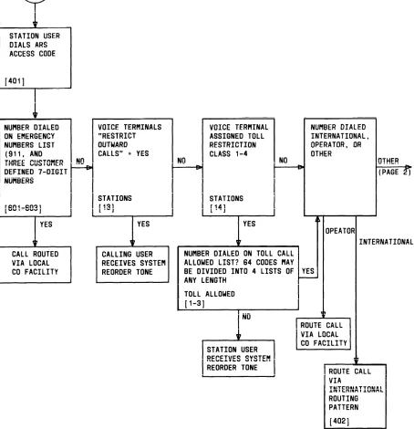
ARS Flow Chart
Figure 2-1 provides a simplified ARS flow chart. Bracketed numbers (e.g., [401], [601] ) provide a link between ARS administrable action numbers and the associated item on the flow chart. Certain readers may find this reference useful when reading the following d e s c r i p t i o n i n a s s o c i a t i o n w i t h t h e S y s t e m A d m i n i s t r a t i o n M a n u a l ( 5 5 5 - 5 0 0 - 5 0 0 ) . Administrable System, Station, Toll Allowed, and Trunk action numbers are also noted where applicable.
The ARS feature is accessed when a user dials the ARS access code. As shown on Figure 2-1, the number dialed is first checked against the Emergency Numbers List. This list consists of special service codes (911) and up to three customer defined seven digit numbers. If the number dialed matches one of the numbers on the list, the call is immediately routed via the local CO facility. All user call restrictions are disregarded.
If the number dialed is not on this list, a check is made to determine if the voice terminal is allowed to originate outside calls. If the terminal is outward restricted, the caller receives Reorder Tone, otherwise, the dialed number is checked against any toll restrictions that apply.
Terminals may be assigned a Toll Restriction Class (l-4), or be unrestricted (Class O). Terminals assigned Toll Restriction Class 1 have the most privileges, those assigned Class 4 have the least privileges. There are four associated Toll Call Allowed Lists (l-4) in the system. Up to 64 3-digit CO codes and 6-digit NPA plus CO codes may be assigned to the four lists (total).
Numbers dialed from voice terminals assigned Toll Restriction Class 1 are checked against all four Toll Call Allowed (TCA) Lists; numbers dialed from Class 2 terminals are checked against TCA Lists 2-4; numbers dialed from Class 3 terminals are checked against TCA Lists 3-4; and numbers dialed from Class 4 terminals are checked against List 4 only. If the number dialed does not appear on a list (all operator and international calls are in this category), the user receives Reorder Tone. Calls originated at unrestricted (Class O) terminals are not screened. Calls are checked to determine if they are international calls or operator calls. Dialed numbers “01” or “011” signify international calls, “O” plus a number other than “l” signify operator calls. If the call is an international call, the international routing pattern is selected and the call routed accordingly. Operator calls are routed via the
local CO facility. .
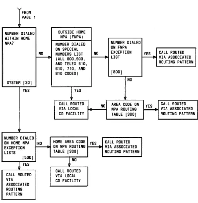
Calls within the HNPA are checked against the HNPA Exception Lists. There may be up to four of these lists, each with an associated ARS Routing Pattern. Up to 64 3-digit office codes may be divided among the four lists (eight of the entries may be 7-digit numbers. ) If a match is found, the call is routed via the associated ARS Routing Pattern. If no match is found the dialed number is routed via the HNPA pattern (specified in the NPA Routing Table), or if none is specified, via the local CO facility.
The NPA Routing Table is simply a listing of North American Plan NPAs, each having an associated ARS Routing Pattern (all North American NPA’s are assigned routing pattern 1 by default.) A dialed NPA that is listed in the table is routed using the associated Pattern. Calls to NPA’s not listed are routed via the local CO facility.
For FNPA calls not on the Special Numbers List, the dialed numbers are checked against the FNPA Exception List. Up to 32 entries maybe assigned to the list. Each entry must consist of a 3-digit NPA code, 3-digit CO code, and two additional digits (8-digits). The last two digits may be “. .“, which match any digit. Each entry has an associated ARS Routing Pattern. If a match is found, the call is routed using this pattern, If no match is found, the call is then checked against the NPA Routing Table. A dialed NPA that is listed in the table is routed using the associated Pattern. Numbers that don’t match are routed via the local CO facility.
ARS Routing Pattern Table
Figure 2-2 provides a block diagram o