AT&T
MERLIN LEGEND
®Communications
System
Release 3.0
System Programming
and
Copyright © 1994, AT&T AT&T 555-630-140
All Rights Reserved August 1994
Printed in U.S.A. Notice
Every effort was made to ensure that the information in this book was complete and accurate at the time of printing. However, information is subject to change.
See Appendix A, “Customer Support Information” following Programming Summary, for important information. Security of Your System: Preventing Toll Fraud
As a customer of a new telephone system, you should be aware that there exists an increasing problem of telephone toll fraud Telephone toll fraud can occur in many forms, despite the numerous efforts of telephone companies and telephone equipment manufacturers to control it. For important information regarding your system and toll fraud, see Appendix A, “Customer Support Information” following Programming Summary. Federal Communications Commission Statement
This equipment has been tested and found to comply with the limits for a Class A digital device, pursuant to Part 15 of the FCC Rules. These limits are designed to provide reasonable protection against harmful interference when the equipment is operated in a commercial environment. This equipment generates, uses, and can radiate radio frequency energy and, if not installed and used in accordance with the instruction manual, may cause harmful Interference to radio communications. Operation of this equipment in a residential area is likely to cause harmful Interference, in which case the user will be required to correct the interference at his own expense. For further FCC information, see Appendix A, “Customer Support Information” following Programming Summary. Canadian Department of Communications (DOC)
Interference Information
This digital apparatus does not exceed the Class A limits for radio noise emissions set out in the radio interference regulations of the Canadian Department of Communications.
Le Présent Appareil Numérique n'èmet pas de bruits radioélectriques dèpassant Ies Iimites applicable aux appareils numèriques de la class A prescribes clans Ie reglement sur Ie brouillage radioélectrique èdicté par Ie ministère des Communications du Canada.
Trademarks
CONVERSANT and MERLIN LEGEND are registered trademarks and AUDIX Voice Power, FAX Attendant System. and MLX-20L are trademarks of AT&T in the U.S. and other countries.
MS-DOS is a registered trademark of Microsoft Corp.
Hayes IS a registered trademark of Hayes Microcomputer Products, Inc. UNIX IS a registered trademark of UNIX System Laboratories, Inc.
Ordering Information
The ordering number for this document is 555-630-140. To order this document, call the AT&T Customer Information Center at 1-800-432-6600 (in Canada, 1-800-255-1242). For more information about AT&T documents, refer to the section entitled, “Related Documents” in “About This Book. ” The Pocket Reference, listed in that section, provides full ordering Information for replacement parts, accessories, and other compatible equipment; or, contact your AT&T representative.
Support Telephone Number
In the continental U. S., AT&T provides a toll-free customer helpline 24 hours a day. Call the AT&T Helpline at 1-800-628-2888 If you need assistance when installing or using your system.
Intended Audience
xiiiTerms and Conventions Used
■ Typographical Conventions ■ Product Safety Labels
Security
Related Documents
How to Comment on This Document
System Requirements
Installing the SPM Software
● DOS Installation
■ Initializing the SPM Software
Connecting the PC
■ Direct Local Connection ■ Local Modem Connection ■ Remote Modem Connection
Accessing SPM
■ With a Direct Local Connection
■ With a Local or Remote Modem Connection
Considerations
Using SPM
■ SPM Screens
■ SPM Main Menu Options ■ SPM Help
■ Backup
Determining the Release Number of a Backup File
■ Boards
xiv xv xv xvi xvi xvii 2 4 4 7 10 11 13 14 15 15 17 17 21 21 26 27 28 28 32
Contents
Using SPM,
continued
■ Browse■ Convert ■ Language
PC Language
Console Window Language
■ Maintenance ■ Monitor ■ Pass-Thru ■ Password ■ Print Options
SMDR Port Output PC Port Output
■ Restore
System Programming
■ Basic Programming Information ■ Idle States
System Forced Idle Line or Trunk Idle Extension Forced Idle Forced Idle Reminder Tone
■ Accessing System Programming ■ Printing Reports
Print Hard Copy Print to Hard Disk Print to Floppy Disk
Upgrading the System
■ Before You Begin
■ Inter-Release Compatibility ■ Upgrade Procedure
Surrogate
Glossary
Index
Mode Programming
63 63 64 66
70
Figures
1.
2.
3. 4. 5. 6. 7.
Direct Local Connection, PC Less Than 50 Feet Away Direct Local Connection, PC More Than 50 Feet Away Local Modem Connection Remote Modem Connection SPM Display
SPM Help Pass-Thru
11
1. 2. 3. 4. 5. 6. 7. 8. 9.
SPM Configuration File (ams.cfg) Options Function of PC Keys in SPM
SPM Main Menu Options
Backup Header: Release Number Board Types
Programming Capability
Programming Needed after Upgrade to Release 1.1 Programming Needed after Upgrade to Release 2.0 Programming Needed after Upgrade to Release 3.0
7 24 26 28 34 65 68 69 70
The exclamation point in an equilateral triangle is intended to alert the user to the
presence of important operating and maintenance (servicing) instructions in the literature accompanying the product.
IMPORTANT SAFETY INSTRUCTIONS
When installing telephone equipment, always follow basic safety precautions to reduce the risk of fire, electrical shock, and injury to persons, including:
Read and understand all instructions.
Follow all warnings and instructions marked on or packed with the product.
Never install telephone wiring during a lightning storm.
Never install a telephone jack in a wet location unless the jack is specifically designed for wet locations.
Never touch uninsulated telephone wires or terminals unless the telephone wiring has been disconnected at the network interface.
Use caution when installing or modifying telephone lines.
Use only AT&T-manufactured MERLIN LEGEND Communications System circuit modules, carrier assemblies, and power units in the MERLIN LEGEND Communications System control unit.
Use only AT&T-recommended/approved MERLIN LEGEND Communications System accessories.
If equipment connected to the analog extension modules (008, 408, 408 GS/LS) or to the MLX telephone modules (008 MLX, 408 GS/LS-MLX) is to be used for in-range out-of-building (IROB) applications, IROB protectors are required.
Safety
Do not install this product near water, for example, in a wet basement location.
Do not overload wall outlets, as this can result in the risk of fire or electrical shock.
The MERLIN LEGEND Communications System is equipped with a 3-wire grounding-type plug with a third (grounding) pin. This plug will fit only into a grounding-type power outlet. This is a safety feature. If you are unable to insert the plug into the outlet, contact an electrician to replace the obsolete outlet. Do not defeat the safety purpose of the grounding plug.
The MERLIN LEGEND Communications System requires a supplementary ground.
Do not attach the power supply cord to building surfaces. Do not allow anything to rest on the power cord. Do not locate this product where the cord will be abused by persons walking on it.
Slots and openings in the module housings are provided for
ventilation. To protect this equipment from overheating, do not block these openings.
Never push objects of any kind into this product through module openings or expansion slots, as they may touch dangerous voltage points or short out parts, which could result in a risk of fire or
electrical shock. Never spill liquid of any kind on this product.
Unplug the product from the wall outlet before cleaning. Use a damp cloth for cleaning. Do not use cleaners or aerosol cleaners.
Auxiliary equipment includes answering machines, alerts, modems, and fax machines. To connect one of these devices, you must first have a Multi-Function Module (MFM).
WARNING:
■ For your personal safety, DO NOT install an MFM yourself.
■ ONLY an authorized technician or dealer representative shall install,
set options, or repair an MFM.
■ To eliminate the risk of personal injury due to electrical shock, DO
NOT attempt to install or remove an MFM from your MLX telephone. Opening or removing the module cover of your telephone may expose you to dangerous voltages.
SAVE THESE INSTRUCTIONS
System Programming and Maintenance (SPM) is a software tool developed specifically for the MERLIN LEGEND Communication System to allow programming, administration, and maintenance tasks to be done on a PC.
Intended Audience
This book is intended for anyone who uses a PC to perform programming or maintenance tasks for the communication system, It is especially aimed at system managers and support personnel.
"Related Documents, ” later in this section, provides a complete list of system documentation together with ordering information.
In the U.S.A. only, AT&T provides a toll-free customer Helpline (1 -800-628-2888) 24 hours a day. Call the Helpline, or your AT&T representative, if you need assistance when installing, programming, or using your system.
Terms and Conventions Used
Terms and Conventions Used
In this document, the terms in the following list are used in preference to other, equally acceptable terms for describing communications systems.
Lines, Trunks and Facilities
Facility is a general term that designates a communications path between a telephone system and the telephone company central office. Technically a trunk connects a switch to a switch, for example the MERLIN LEGEND Communications System to the central office. Technically, a line is a loop-start facility or a communications path that does not connect two switches, for example, an intercom line or a Centrex line. However, in actual usage, the terms line and trunk are often applied interchangeably. {n this book, we use line/trunk and lines/trunks to refer to facilities in general. Specifically, we refer to digital facilities. We also use terms such as personal line, ground-start trunk, DID trunk, and so on. When you talk to your local telephone company central office, ask them what terms they use for the specific facilities they connect to your system.
Some older terms have been replaced with newer terms, The following list shows the old term on the left and the new term on the right.
trunk module trunk jack station station jack
analog data station digital data station
analog voice and analog data station digital voice and analog data station analog data only station
digital data only station
digital voice and digital data station
line/trunk module -line/trunk jack
extension extension jack modem data station 7500B data station
analog voice and modem data MLX voice and modem data modem data only station 7500B data only station
Typographical Conventions
Certain type fonts and styles act as visual cues to help you rapidly understand the information presented:
Example Purpose
It is very important that you follow these steps. You must attach the wristband before touching the connection.
The part of the headset that fits over one or both ears is called a
headpiece.
If you press the Feature button on an MLX display telephone, the display lists telephone features you can select. A programmed Auto Dial button gives you instant access to an inside or outside number.
Choose Ext Prog from the display screen.
To activate Call Waiting, dial *11.
Product Safety Labels
Italics indicate emphasis
Italics also set off special terms.
The names of fixed-feature, factory-imprinted buttons appear in bold. The names of
programmed buttons are printed as regular text.
Plain constant-width type
indicates text that appears on the telephone display or PC screen. Constant-width type in italics indicates characters you dial at the telephone or type at the PC.
Throughout these documents, hazardous situations are indicated by an exclamation point inside a triangle and the word caution or warning.
WARNING:
Warning indicates the presence of a hazard that could cause death or severe personal injury if the hazard is not avoided.
Security
CAUTION:
Caution indicates the presence of a hazard that could cause minor personal injury or property damage if the hazard is not avoided.
Security
Certain features of the system can be protected by passwords to prevent unauthorized users from abusing the system. You should assign passwords wherever you can and limit knowledge of such passwords to three or fewer people.
Nondisplaying authorization codes and telephone numbers provide another layer of security. For more information, see Appendix A, “Customer Support Information. ”
Related Documents
In addition to this book, the documents listed below are part of the
documentation set. Within the continental United States, these-documents can be ordered from the AT&T Customer Information Center by calling 1-800-432-6600.
Document No. Title
System Documents 555-630-117 Introduction
555-630-118 System Manager’s Guide 555-630-110 Feature Reference
555-630-115 Equipment and Operations Reference 555-630-116 Pocket Reference
555-630-111 System Programming 555-630-112 System Planning
Telephone User Support
555-630-122
MLX-10D™, MLX-10DP™, MLX-28D™, and MLX-20L™I
Display Telephones User’s Guide555-630-150 MLX- 10D Display Telephone Tray Cards (5 cards) 555-630-153 MLX-28D and MLX-20L Telephone Tray Cards (5 cards) 555-630-124
I .
MLX- 10™ Nondisplay Telephone User’s Guide
555-630-151 MLX-10 Nondisplay Telephone Tray Cards (6 cards) 555-630-120 Analog Multiline Telephones User’s Guide
555-630-126 Single-Line Telephones User’s Guide
System Operator Support
555-630-134
MLX Direct-Line Consoles Operator’s Guide 555-630-132 Analog Direct-Line Consoles Operator’s Guide 555-630-136 MLX Queued Call Console Operator’s Guide555-630-138 MDC 9000 and MD W 900 Telephones User’s Guide
Miscellaneous User Support 555-630-130 Calling Group Supervisor’s Guide 555-630-129 Data User’s Guide
Documentation for Qualified Technicians
555-630-140 Installation, Programming, & Maintenance (IP&M) Binder.
How to Comment on This Document
We welcome your comments, both good and bad. Please use the feedback form on the next page
feedback form is miss
to let us know how we can continue to serve you. If the ing, write directly to:
Documentation Manager AT&T
211 Mount Airy Road Room 2W226
Basking Ridge, NJ 07920.
The System Programming and Maintenance (SPM) software package offers an alternate method of programming the MERLIN LEGEND Communication System using a PC. This method frees the system programming console for other uses and also provides the additional functions listed below:
■ Backing up system programming information
■ Restoring system programming information from a backup
■ Converting system programming information from one release to
another (part of the upgrade procedure)
■ Upgrading your communications system to a newer release ■ Printing, viewing, and storing reports
■ Programming the communications system remotely ■ Programming in surrogate mode
SPM runs on a DOS-based PC as a stand alone program or on a UNIX® System platform as part of Integrated Solution II or Integrated Solution Ill (IS II/III). It is available on a 3.5-inch diskette for DOS or UNIX, or on a 5.25 inch diskette for DOS.
NOTE:
SPM software can be used directly from the floppy disks on a DOS machine; however, if your PC has a hard disk, you should install SPM onto the hard disk.
System Requirements
This book describes the use of SPM on a PC with a DOS operating system. If your system has the IS II/III application, you have the UNIX System version of SPM.
For information about accessing SPM from the IS II/III application, refer to the following books:
■ integrated Solution Ill System Manager’s Guide, order no. 555-601-010 ■ Integrated Solution III lnstallation and Maintenance Guide, order no.
555-601-011
■ Integrated Solution II System Manager’s Guide, order no. 555-600-726 ■ Integrated Solution II Installation and Maintenance Guide, order no.
555-600-720
System Requirements
To use SPM for system programming, you need the SPM diskette and an approved PC with version 3.3 (or later) of MS-DOS®. At a minimum, your PC should support and include the following items:
■
■
■ ■
■
At least 640 kbytes of RAM
A floppy disk drive that will accommodate the SPM diskette (3.5-inch or 5.25-inch)
A monochrome or color monitor
A serial port (either COM1 or COM2) that can use either a 9 or DB-25 connector
For a DB-9 connector, use a 9-pin to 25-pin adapter to attach the 25-pin connector of the RS-232 interface cable.
Depending on how you connect the PC to the control unit, you will also need the following items:
■ Direct local connection, with the PC within 50 feet of the control unit.
Either a 355AF modular adapter (if there is a male connector on the interface cable) or a 355A modular adapter (if there is a female connector on the interface cable)
A 4-pair modular cord (D8W)
■ Direct local connection, with the PC more than 50 feet from the control
unit.
355AF adapter
EIA crossover cable
Two Z3A2 Asynchronous Data Units (ADUs)
ADU crossover cable
400B2 power adapter
2012D transformer
BRIA-4P adapter and 102 connecting block or 103 connecting block
248B adapter
8-position wall jacks
4-pair plug-ended cable
D8W cords
D6AP power cord
EIA-232-D cables
■ Modem (local or remote) connection
A modem that supports 1200- or 2400-bps connections
Installing the SPM Software
In addition, a parallel printer is useful for reports (the PC needs a parallel port for the connection).
NOTE:
SPM uses Interrupt 4 and I/O address 3F8 for COM1. It uses Interrupt 3 and I/O address 2F8 for COM2.
Installing the SPM Software
Before you install or run SPM, use diskcopy on a DOS PC (see your operating system guide) to make a backup copy of the SPM diskette and store the original in a safe place. Use the backup copy to run the installation program.
For installing SPM on a DOS PC, follow the appropriate instructions in the next section of this book.
NOTE:
If your PC does not have a hard disk, you do not need to run the installation program. Go to “Initializing the SPM Software. ”
DOS Installation
Use the following procedure to install SPM on the hard drive of a DOS PC.
NOTE:
If you are updating SPM, you do not need to remove the current SPM files. The new files will overwrite your current SPM files.
Considerations
The installation program automatically performs the following:
Checks available space on the hard disk. If space is insufficient, the installation is terminated and an error message is generated.
Checks the autoexec.bat and config.sys files. If either file is
write-protected, the installation is terminated and an error message is generated. SPM must make changes to these files.
Saves a copy of autoexec.bat as autoexec.old.
Saves a copy of config.sys as config.old.
If autoexec.bat has not already been configured for SPM, performs the following:
Adds c: \spm to the path statement
Adds the line SET AMS PATH=C:—
Adds the background print command
PRINT /D:PRN/B:4096/U:3/M:200/S:1>NUL
Adds the following line to config.sys if it is not already present
DEVICE=C:\ANSI.SYS.
Copies the ansi.sys file from the floppy disk to c:\.
Creates the directory c:\spm.
Copies the following files from the floppy disk into c:\spm:
spm.exe
ams_hlp.eng (English language help file)
ams_hlp.fre (French language help file)
ams_hlp.spa (Spanish language help file)
Creates the following directories if they do not
c:\spm\backup
c:\spm\reports
c:\spm\tmp.
already exist:
Installing the SPM Software
■ Does one of the following:
Creates the SPM configuration file c:\spm\ams.cfg, if it does not already exist. In this case, the ares.cfg file consists of only one line, in which the language attribute is specified: LANG 1 if you specified English or did not specify a language with the install command;
Modifies the ares.cfg file, if it already exists, by adding or changing the LANG value.
Follow the steps below to install SPM on the PC’S hard disk.
1 Switch to Drive A, if it is not already the current drive.
A:> appears on the screen.
2 Insert the backup copy of the SPM diskette into Drive A.
3 Type one of the commands shown below and press (Enter
↵
) .■ install spanish
Because English is the default language, install and install english have the same result. If you do use the language argument (english, french, or
spanish), you must type it in lowercase letters as shown. The command install may be upper case or lower case.
4 Wait for the message shown below to appear.
SPM1 HARD DISK INSTALLATION PROGRAM Strike a key when ready
5 Press any key to begin the installation.
When the installation is finished, the following message appears:
SPM HARD DISK INSTALLATION IS NOW COMPLETE YOU MUST REBOOT YOUR SYSTEM BEFORE USING SPMl
6 Remove the SPM diskette from Drive A and reboot your system.
Initializing the SPM Software
To run correctly, the DOS version of SPM requires certain information (transmission speed, type of monitor, and so on). You need to supply this information only once, the first time you run SPM.
The information you provide during the initialization process is written to the SPM configuration file (ams.cfg). If you need to change this information at some later time, you can do so in either of the following ways:
■ Use any of the options in Table 1 to change the information in ams.cfg.
■ Edit the ares,cfg file, (If you are unsure about editing the file, you can
remove it. You are prompted to reinitialize the next time you invoke SPM. The file is created at that time.)
NOTE:
The DEBUG attribute is also specified in ams.cfg as DEBUG=0 (off), the default setting, or DEBUG=l (on). This attribute is used to enable the Escape-to-Shell feature of SPM, activated by pressing (Ctrl) + (F9) . To turn DEBUG on, you must edit the ams.cfg file; it is not part of the initialization process. The DEBUG attribute is for use by qualified service personnel only.
Table 1. SPM Configuration File (ams.cfg) Options
OPtion Use
spm -coml spm -com2 spm -s1200 spm -s2400 spm -color spm -mono spm -1 english spm -1 french spm -1 spanish
Specifies COM1 as the serial communications port used by SPM Specifies COM2 as the serial communications port used by SPM Specifies modem speed of 1200 bps
Specifies modem speed of 2400 bps Specifies color monitor
Specifies monochrome monitor
Specifies English as the PC language ‘
Specifies French as the PC language Specifies Spanish as the PC language
Installing the SPM Software
Follow the steps below to perform the SPM initialization.
1
2
3
4
Type spm and press (Enter
↵
) to display the SPM Welcome screen shown in S t e p 2 .■ Make your entry at the C:> prompt if your PC has a hard disk.
■ Make your entry at the A:> prompt if you are using the floppy drive.
Press any key.
Welcome to SPM The MERLIN LEGEND System Programing & Maintenance Utility
Please press any key to continue
Version X.XX
X.XX = current version of SPM
4
The screens shown in Steps 3 through 7 appear only if the system has not been initialized. Otherwise, the screen shown in Step 8 appears.
Select the serial communications port used for SPM and press (Enter
↵
) .COMM PORT: Type 1 for serial port 1 (COM1).
Type 2 for serial port 2 (COM2).
1. Comm 1 2. Comm 2
Enter selection #
Select the communications port speed and press (Enter
↵
) .
speed Type 1 for 1200 bps. 1. 1200 Type 2 for 2400 bps. 2. 2400
5 Respoond to the color prompt and press (Enter
↵
) .COLOR
Enter selection (y/n):
Type y
Type n
6 Select a language and press (Enter
↵
) .Language: 1. English 2. French 3. Spanish
Enter selection #:
Type 1
Type 2
Type 3
if you have a color monitor.
if you do not have a color monitor.
for English. for French. for Spanish.
The language you select here becomes the SPM (PC) language. 7 Review your selections.
SPM CONFIGURATION: Comm Port: x Speed: x Color: x
Desire change (y/n)?
x = the values entered for each entry in Steps 3 through 6
■ To change any of the information shown, type y and press (Enter
↵ ).
The screen shown in Step 3 appears. Repeat Steps 3 through 6.■ To save the information shown, type n and press (Enter
↵
) . If the PC is connected to the processor, the SPM Main Menu appears as shown in Step 8.If the PC is not connected, go to “Connecting the PC. ”
Connecting the PC
8 Press the function key that corresponds to the option you want.
SPM Main Menu I Menu: Select Function I
(F1) Sys Program Maintenance (F6)
(F2) Backup Restore (F3) Boards
(F7)
Pass-Thru
(F4) Print Opts Password
(F8)
(F5) Monitor
(F9)
Language (F10)
NOTE:
The function keys shown on either side of the display are included here for quick reference, See “SPM Screens” for details on using the PC keys in SPM.
Connecting the PC
There are three ways to connect the PC to the control unit. Choose the method below that is most useful for your installation.
■ ■ ■
Direct local connection
Local modem connection
Direct Local Connection
For a direct local connection, you must connect the PC to the system programming jack. This is the lower modular RS-232 jack on the processor module, as shown in Figure 1. (The upper jack is reserved for the SMDR printer. )
To connect a PC more than fifty feet from the control unit, see Figure 2.
For direct local connections, the system supports speeds of 1200 and 2400 bps.
NOTE:
You must use a direct local connection to program in surrogate mode.
Serial System Communications
Jack
Programming Port
R S - 2 3 2 D 8 W
3 5 5 A F Adapter
Figure 1. Direct Local Connection, PC Less Than 50 Feet Away
Connecting the PC
Processor Module
SMDR J a c k ADMIN J a c k 8DW
355AF Adapter EIA
Crossover Cable
EIA-232-D
Z3A2 ADU
4 Pair Plug Ended Cable
D8W
ADU Crossover Cable Control Unit
400B2 D6AP
Power 2012D-50M
Adapter Transformer AC I
or Direct Connection
Wall BR1A-4P Adapter Jack
102 Connecting Block Building
Wiring 103 Connectlng Block DIW
I 1
Wall Jack
102 or 103 Connecting Block
Outlet
D8W
D 8 W EIA-232-D o r Z3A2 ADU
Cable Joints
Local Modem Connection
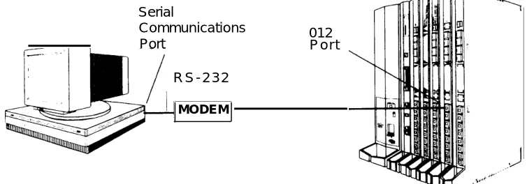
For a local modem connection, you must use a modem (either connected to, or built into the PC) to access the internal modem in the control unit. Connect the modem to an 012 module in the control unit, as shown in Figure 3.
The internal modem operates at speeds of 1200 and 2400 bps.
Serial
Communications 012
Port P o r t
R S - 2 3 2
MODEM
Figure 3. Local Modem Connection
Connecting the PC
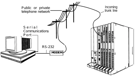
Remote Modem Connection
For a remote modem connection, you must use a modem (either connected
to, or built into the PC) to access the internal modem in the control unit. You must also use a dial-up connection, as shown in Figure 4. See “Accessing
SPM” for details on accessing SPM with a remote modem connection.
The internal modem operates at speeds of 1200 and 2400 bps.
Public or private telephone network
Incoming trunk line
S e r i a l
Communications P o r t
RS-232
MODEM
Figure
4. Remote Modem ConnectionNOTE:
Remote access (modem connection) has priority over local access (direct connection), unless a backup or restore procedure is in progress through a direct local connection. If a modem connection is attempted while any other type of on-site programming is in progress (either at the system console or at a directly-connected PC), the system sends a message to the on-site
programmer. The message indicates that a modem connection is being established and the on-site programming session is terminated.
Accessing SPM
The procedure for accessing SPM depends on whether your PC is connected to the control unit with a modem (either local or remote) or without a modem (direct). This section covers both of these access procedures.
With a Direct Local Connection
To access SPM when your PC is connected directly to the control unit, follow the steps below.
1 Set up the appropriate physical connections between the PC and the control unit.
See “Connecting the PC.”
2 If you installed SPM on the hard disl of the PC , go to Step 5.
3 If the PC does not have a hard disk, insert the SPM diskette into Drive A.
4 Type a: and press (Enter
↵
) .A:> appears on the screen.
Accessing SPM
5 Type spm and press (Enter
↵
) to display the SPM Welcome screen shown. b e l o w .Welcome to SPM The MERLIN LEGEND System Programming & Maintenance Utility Please press any key
to continue Version X.XX
X.XX current version of SPM
6 Press and key to display the SPM Main Meu below.
(F1) (F2)
(F6) (F7) (F8) (F3)
(F4) (F5)
SPM Main Menu Menu: Select Function Sys Program Maintenance Backup Restore Boards Pass-Thru
Print Opts Password (F9)
I Monitor Language (F10)
■ If the SPM Main Menu does not appear or if the information on the
screen is garbled, press any key again.
■ If the COM Port (communications port) screen appears instead of the
SPM Main Menu, it indicates that the SPM software has. not been initialized. See “Initializing the SPM Software.”
NOTE:
The function keys shown on either side of the display are included here for quick reference. See “SPM Screens” for details on using the PC keys in SPM.
With a Local or Remote Modem Connection
The method you use to access SPM by modem depends on whether you are programming on site (locally) or from a remote location.
■ If you are on site, the modem must be connected to an 012 module on
the control unit. To establish a connection to the control unit’s internal modem, dial *10.
■ If you are at a remote location, do one of the following:
Place a call to the system on a Remote Access line, enter the barrier code (if required), and dial the code for the internal modem
(*10).
Place a voice call to the system using the line to which the modem is connected and ask the operator to transfer you to the modem (by pressing Transfer, dialing *10, then hanging up the telephone).
When you hear the modem
Considerations
Review the following items before you procedure.
Set the Programming Language
answer tone, switch to data mode.
begin the modem connection
If you prefer to program in a language other than the current SPM language setting, see “Language.”
Accessing SPM
Modem Connections
You must make a data connection to a modem. The following modem dialing commands are for Hayes® and Hayes-compatible modems. These may not be the commands your modem use-refer to the user guide that came with your modem for specific information.
If the PC is in the same location as the control unit, type *10.
If the PC is in a remote location and your system has activated the Remote Access feature, type the following and press (Enter
↵
) .Without barrier codes type:
ATDT; the remote access telephone number; and W*10.
For example: ATDT12015551234 W*10 (Enter
↵
) .With barrier codes type:
ATDT; the remote access telephone number; the barrier code preceded by a “W” and W*10. The barrier
below is 555555.
For example: ATDT12015551234 W555555
The password prompt appears on the screen
code in the example
W*10 (Enter
↵
) .when the connection is made. (You may have to press (Enter
↵
) more than once to get the password prompt.)If the PC is in a remote location and your system has not activated the Remote Access feature, do the following:
— Use the main telephone number to place a voice call to the system on the line to which the modem is connected.
— Instruct the operator to transfer you to the modem (by pressing
Transfer, dialing *10, then hanging up the telephone).
— To put the modem on line, type ATH1 and press (Enter
↵
) , then hang up the telephone.NOTE:
To access SPM through a local or remote modem connection, follow the steps below.
1 Sep up the appropriate physical connections between the PC and the control unit. See "Connecting the PC."
2 Type spm and press (Enter
↵
) to display the SPM Welcome screen shown b e l o w .Welcome to SPM The MERLIN LEGEND System Programming & Maintenance Utility
Please press any key to continue
Version X.XX
X.XX = current version of SPM
If you wish to program in a language other than the current language set for SPM, see “Set the Programming Language.”
3 Press and key to display a blank screen on which you can enter modem commands. (You may have to press the key several times.)
4 Make a data connection to the modem of the control unit.
See “Modem Connections.” When the connection is made, the password prompt appears as shown in Step 4.
5 Type the SPM password to display the SPM Main Menu shown in Step 6.
Enter Password:
The password does not display as you type it.
Accessing SPM
6 To select an option, press the function key that corresponds to the option you want. For example, to select Language press ( F 1 0 ) .
(F1) (F2) (F3)
(F6) (F7)
(F4) (F5)
SPM Main Menu Menu: Select Function Sys Program Maintenance Backup Restore Boards Pass-Thru Print Opts Password Monitor Language
(F8) (F9) (F10)
NOTE:
Using SPM
This section describes how to use the SPM screens, SPM Help, and the SPM options listed below.
■ Backup
■ Boards
■ Browse
■ Convert
■ Language
■ Maintenance
■ Monitor
■ Pass-Thru
■ Password
■ Print Options
■ Restore
■ System Programming
NOTE:
Some of the procedures described in this section should be performed by qualified service personnel only.
SPM Screens
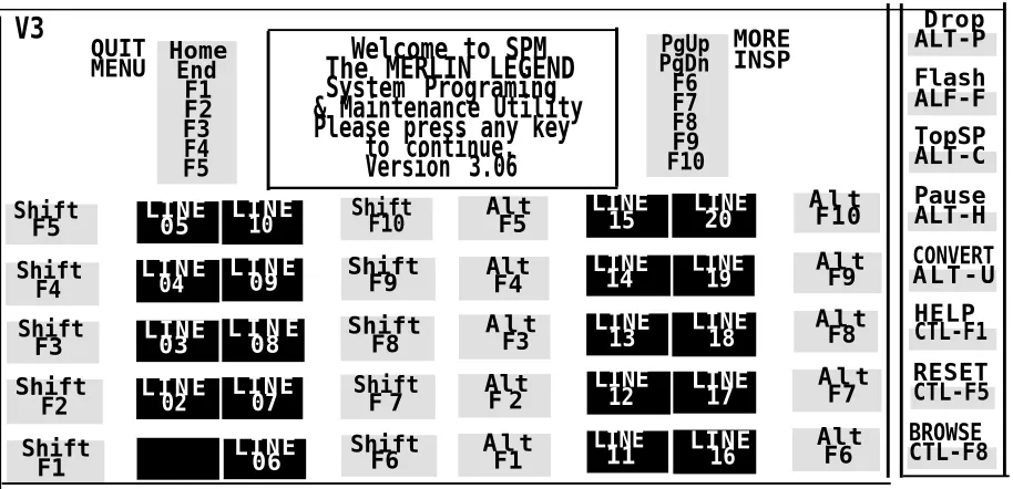
SPM screens simulate the system programming console. Each SPM screen includes a 7-line by 24-character console simulation window that corresponds to the display area of the MLX-20LTM
telephone. To the right and left of this console simulation window are columns that list the keys corresponding to similarly located buttons on the MLX-20L telephone. If you are working with Version 2.0 or higher, the version number appears in the upper left corner of the screen (for example, V3). Figure 5 illustrates the SPM display screen.
Using SPM V3 PgUp PgDn F6 F7 F8 F9 F10 MORE INSP Drop ALT-P QUIT
MENU HomeEnd F1 F2 F3 F4 F5
Welcome to SPM The MERLIN LEGEND System Programing & Maintenance Utility Please press any key
to continue. Version 3.06 Flash ALF-F TopSP ALT-C Shift
F5 LINE05 LINE10 ShiftF10 AltF5
LINE
15 LINE20
A l t F10
Pause ALT-H
Shift F4
L I N E
04 L I N E09 ShiftF9 AltF4
LINE
14 LINE19 A l tF9
CONVERT A L T - U
Shift
F3 LINE03 L I N E08 ShiftF8
A l t F3
LINE
13 LINE18
A l t F8
HELP CTL-F1
Shift
F2 L I N E02
LINE
07 ShiftF 7 AltF 2
LINE
12 LINE17 A l tF7
RESET CTL-F5
Shift F1
LINE
06 ShiftF6 A l tF1
LINE
11 LINE16
Alt F6
BROWSE CTL-F8
Figure 5.
SPM Display
F1 through F5, and F6 through F10 display on either side of the console
Below the console simulation window are 20 simulated line buttons. The 20 line buttons can be selected using the arrow keys to position the cursor on the appropriate button. Using [PgDn] (the Inspect feature), you can determine the status of each line and the features programmed on each line according to the letter that appears next to the line number (see below).
On the PC screen, the letters R and G represent the ON state of the red and green LEDs, respectively, that are on the console. For example, if a line, trunk, or pool is assigned to a line button, on the console a green LED lights next to the button. On the PC screen, the letter G (for green) displays next to the button. Similarly, if a line, trunk, or pool is not assigned to a line button, neither
G nor R display next to the button on the PC screen. If a trunk is assigned to a pool, an R (for red) displays on the PC screen.
The labels in the column on the right side of the screen show key
combinations that correspond to buttons on the MLX-20L telephone. Table 2 describes the function of PC keys in SPM.
Using SPM
Table
2. Functionof PC Keys in SPM
PC Key
Console
SPM Function
(Home) Home Quit. Exit from SPM and return to the DOS prompt when you finish with system
programming. If you are using a modem, the call is disconnected.
(End) Menu Return to the SPM Main Menu.
(PgUp) More Display more menu items (when there is
another screen and the > symbol appears next to the key).
(PgDn) Inspct Show the current information that has been programmed for a feature or button.
(Alt) + (P) Drop Enter a stop in a speed dialing sequence. This combination also deletes an entry in a field on any screen except one in which you are
entering a speed dialing sequence.
(Alt) + (F) Conf Flash. Enter a switchhook flash in a speed
dialing sequence.
(Alt) + (C) n/a TopSP. Return to the top of the System
Programming menu.
(Alt) + (H) Hold Pause. Enter a pause in a speed dialing
sequence.
(Alt) + (U) n/a Convert. Convert a backup file from its original
Release format to a different Release format. (Alt) + (N) n/a Toggle modem speed between 1200 to
2400 bps.
(Ctrl) + (F1) n/a Help. Display a help screen about SPM
operations. To exit from Help, press (End).
Table 2- Continued
PC Key Console SPM Function
(Ctrl) + (F5) n/a Reset. Reset the communications port. For example, if the information on the screen is garbled, try exiting from and then recentering the screen. If the screen remains garbled, use
(Ctrl) + (F5) to clear the screen and return to the SPM Welcome screen. Note that using (Ctrl) +
(F5) drops the modem connection.
(Ctrl) + (F8) n/a Browse. View print reports saved with Print opts.
(Ctrl) + (F9) n/a Escape to shell. To use this key sequence, you must set DEBUG=1 in the SPM configuration file ams.cfg. You can then use this key sequence to execute DOS (or UNIX System) commands. To return to SPM, type exit.
(Enter
↵
) Enter The (Enter↵
) key on your PC can be usedinstead of (F10) when Enter appears as a choice
in the console simulation window.
(Bksp) Backspace The (Bksp) key on your PC can be used instead of (F9) (Backspace) when it appears as a choice in
the console simulation window.
(Del) Delete The (Del) key on your PC can be used instead of (F8) (Delete) when it appears as a choice in the console simulation window.
( ^ ) ( v ) n/a The up, down, left, and right arrow keys can be
(< ) ( >) used to highlight selections in a menu and toselect the 20 line buttons below the console
simulation window.
Using SPM
SPM Main Menu Options
The SPM Main Menu provides access to system programming functions listed in Table 3.
Table
3. SPMMain Menu Options
and to the SPM
SPM Menu
FunctionSys Program To program the system
Backup* To make a backup copy of your system programming and store it
on diskette or on hard disk
Boards* Shows which modules (port boards) are in each slot of the control
unit and allows you to assign boards to slots
Print Opts* Directs reports to the printer or to the PC for storage on diskette or
hard disk
Monitor* Restricted to use by your technical support organization Maintenance Restricted to use by your technical support organization and
qualified technicians
Restore* To restore your system programming from diskette or hard disk Pass-Thru* (IS II/III only) To make a remote connection, through the control
unit, to an IS II/III PC to administer applications on the IS II/III PC.
Password* To change the password for remote entry into the system.
Language To select a language (English, French, or Spanish) for the console
simulation window on the PC. (There is also a Language option available on the System Programming menu that allows you to set the system language.)
SPM
Help
To
To
To
To
access the SPM help screens, press (Ctrl) + (F1).
review the help screens press, (PgUp) and (PgDn).
return to the first Help screen, press (Home) .
exit from SPM Help, press (End).
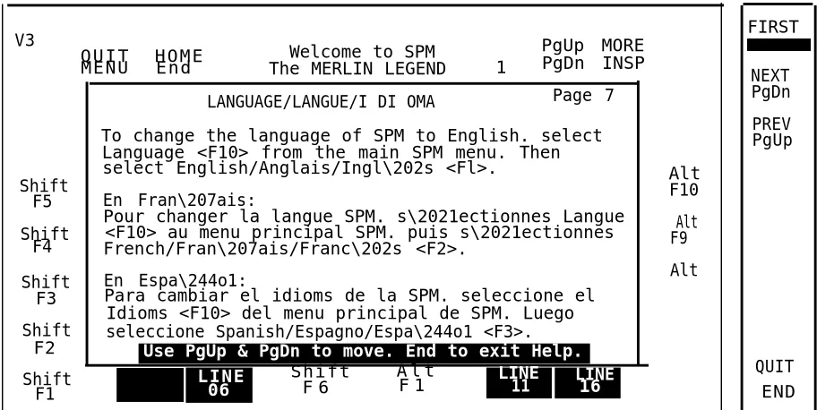
A typical help screen is shown in Figure 6.
V3
M E N U E n d
Q U I T H O M E Welcome to SPM
1
PgUp MORE The MERLIN LEGEND PgDn INSP LANGUAGE/LANGUE/I DI OMA Page 7
To change the language of SPM to English. select Language <F10> from the main SPM menu. Then select English/Anglais/Ingl\202s <Fl>.
Shift Alt
F5 En Fran\207ais: F10
Pour changer la langue SPM. s\2021ectionnes Langue
Shift <F10> au menu principal SPM. puis s\2021ectionnes Alt French/Fran\207ais/Franc\202s <F2>. F9 F4
Shift En Espa\244o1: Alt
F3 Para cambiar el idioms de la SPM. seleccione el Idioms <F10> del menu principal de SPM. Luego Shift seleccione Spanish/Espagno/Espa\244o1 <F3>.
F2 Use PgUp & PgDn to move. End to exit Help.
Shift L I N E S h i f t A l t LINE LINE
F1 06 F 6 F 1 11 16
Figure 6. SPM Help
FIRST
NEXT PgDn PREV PgUp
QUIT END
Using SPM
Backup
The Backup procedure is used by qualified service personnel to create a file
of system programming information in the \spm\backup directory (on the hard -drive of the PC) or in the root directory of a diskette (on the floppy disk -drive of the PC).
NOTES:
1.
2
Back up your system programming information on a regular basis. A current backup file allows you to quickly and easily restore your system, if the need arises.
With Release 3.0 and later, system programming can be backed up or restored from a PCMCIA memory card. See Chapter 22, “Memory Card,” for more information.
Determining the Release Number
of a Backup File
If you have a backup diskette but do not know its release number, you maybe , able to find this information in the backup header. Beginning with later \ versions of Release 1.1, the backup file contains a backup header 128 bytes long. Approximately 59 of these bytes are currently used. Bytes 55 through 59 of the header contain the MERLIN Legend Communication System Release number, as shown in Table 4. (Release 1.0 and early versions of Release 1.1 do not contain this information in readable form.)
Table
4.Backup Header Release Number
Release No.
Build No. System Size Mode
Size 2 bytes 12 bytes 1 byte 1 byte
Examples 03 00 32 01 01, - Key
02 01 02- Behind Switch
The release number is found in the first two bytes (four characters) of the identification number. For example, 0300 = 3.0, 0201 = 2.1.
If the backup file is compressed, you can read the header but you cannot read the data area following the header. Use type [backup filename] to read
the header on a DOS system or cat [backup filename] to read the header on a UNIX System.
Note that the communication system release number, not the version number of SPM, reflects whether the backup file is compressed or uncompressed. Release 1.0 backups are uncompressed and Release 1.1 and later backups are compressed. Uncompressed files take longer to restore.
Considerations
Review the following items before you begin the backup procedure:
■
■
■
■
■
Follow
The communications system does not have to be idle during backup; however, extension programming is blocked.
Any objects that are in a maintenance-busy state are stored in that state. When you restore system programming, these objects are busied out, even if they have since been released from the maintenance-busy state.
If you plan to store your backup file on a diskette, format a DOS diskette. (DOS formatting can be done on a UNIX System PC or a DOS PC).
Uncompressed backup files are 100,000 to 210,000 bytes in size; compressed files are about 70,000 to 85,000 bytes.
Maintenance data (error logs and other data used by qualified service technicians) is not saved in the backup file.
the steps below to perform the backup procedure.
Using SPM
1 At the SPM Main Menu, press (F2) to select backup.
(F2)
L
SPM Main Menu Menu: Select Function Sys Program Maintenance Backup Restore Boards Pass-Thru Print Opts Password Monitor Language
2 Follow the instructions for a floppy or a hard disk.
A second window apperars which displays the GOTO FLOPPY and MAKE NEW FILE options and a directory listing for the C:\spm\backup directory.
■ If you are saving the backup file to a floppy disk, go to Step 3. ■ If you are saving the backup file to the hard disk, go to Step 4.
3 Remove the SPM diskette and insert a formatted diskette. Use the arrow keys to highlight GOTO FLOPPY and press (Enter
↵
).After you press (Enter
↵
), to
GOTO FLOPPY statement shown above changes toGOTO HARD DISK and the directory listing for A:\is displayed. Continue with Step 4.
The screen displays the default name for the backup file (bakup.ams).
4 Specify a backup filename.
To select the default filename use the arrow keys to highlight
backup.ams and press (Enter
↵
) . Go to Step 6.5 Type the new filename and press (Enter
↵
) .Press ESC to
Enter filename:
Abort.
(*fault is backup.ams)
If you are working from the floppy drive,
A:\ appears on the screen.
You can specify a drive letter with the filename but no path information. 6 Verify that the filename chosen does not already exist.
The following screen appears only if the filename chosen already exists. Continue with Step 7 if this screen does not appear.
The file already exists.
If you continue, the old Press (Esc) to abort the backup. Go to
version will be deleted. Step 1 to create a different backup file.
Press ESC to abort.
Press “c” to continue. Press (C) to continue. Go to Step 7.
7 Observe the backpstaus screen
Press ESC to Abort. Est. Blocks: xxx - xxxx
filename
BACKUP IN PROGRESS Received Block xx
flename = the backup filename specified in Step 5
SPM indicates the status of the backup by displaying the number of the last block received (xx). Line 2 of the display screen shows the estimated number of blocks to be sent from the control unit (XXX-XXXX). This line is blank if you are backing up from Release 1.0.
If you abort the backup, the partial backup file is deleted to prevent restoration from a corrupted file and you see the screen shown in Step 8.
Using SPM
When the backup is complete, you see the screen shown in Step 9.
8 To abort the backup press (Esc) ro reurtn to the SPM Main Menu.
Backup aborted Please press Enter to see the Main Menu:
9 When the backup is complete, press (Enter
↵
) to return to the SPM Main M e n u .Backup successful. xxx = total number of blocks received
Please press Enter to see the Main Menu Received xxx Blocks.
Boards
The Boards option allows qualified service personnel to add a board to the next available slot. The system must be idle to use this option. This option is not available from the system programming console.
The Boards option is also available in surrogate mode. In surrogate mode, you can assign trunk and extension modules (boards) to slots, even though the boards have not actually been installed. This type of board is referred to as a “phantom” or “null” board.
You cannot use the Boards option to change an actual board type. All boards assigned with the Boards option, including phantom boards, are cleared
NOTES:
1.
2.
You must assign phantom boards to higher slot numbers than any real boards you assign. If you assign a phantom board to a lower slot number than a real board, the control unit does not recognize the real board(s) that follow the phantom board.
If you remove a board but do not replace it, and then perform a board renumber, the control unit will not recognize any boards that follow the empty slot. You must reseat all of the boards to fill the empty slot before you perform the board renumber.
The Inspect function ([PgDn]) lets you see which modules have been assigned to slots on the control unit. Note that both phantom
display if you use the Inspect function. To see only you must print the System Information report:
System> More> Print>SysSet-up.
boards and real boards real board assignments,
Table 5 shows the type of boards that you can select.
Using SPM
Table 5. Board Types
Board Type
400LSR
400GLR
800LS
800GLID
8OOGLS
408LSA
408GLA
408GLM
O08ATL
O08MLX
012TR/OPT
800DID
400E&M
100D
517A31
Description
4 loop-start line jacks with 4 touch-tone receivers
4 ground-start/loop-start line jacks with 4 touch-tone receivers 8 loop-start line jacks
8 ground-start/loop-start line jacks with Caller ID capability available on the loop-start lines and 2 touch-tone receivers
8 ground-start/loop-start line jacks
4 loop-start line jacks and 8 ATL analog extension jacks
4 ground-start/loop-start line jacks and 8 ATL analog extension jacks
4 ground-start/loop-start line jacks and 8 MLX extension jacks (16 endpoints)
8 analog extension jacks
8 MLX-20L extension jacks(16 endpoints)
12 tip/ring extension jacks with 2 touch-tone receivers or 008 OPT jacks
8 DID trunk jacks with 2 touch-tone receivers 4 E&M tie trunk jacks
1 DS1 jack (24 channels)
1 At the SPM Main Menu, press (F3) to select Boards.
2 Press the funciton key that corresponds to the module you want to s e l e c t .
Follow the steps below to assign modules.
(F3) (F6) (F7) (F8) (F9) (F10) (F1) (F2) (F3) (F4) (F6) (F7)
3 Type the control unit slot number (01 through 17) in which the module is to be installed.
module name
Enter slot numbers (01-17)
Delete Backspace Next Exit Enter
SPM Main Menu Menu: Select Function Sys Program Maintenance Backup Restore Boards Pass-Thru Print Opts Password Monitor Language (F1) (F2) (F3) (F4) (F5) 4Boards: > Make a selection
408LSA 800LS O12TR/OPT 008ATL 800DID 008MLX 800GLS 400GLR
Exit 400LSR (F5)
Boards:
Make a selection
400E&M 800GLID 408GLA 517A31 100D
408GLM Exit
If the module you want to assign is not shown on the first screen of the Boards menu, press (PgUp) to display the next menu screen.
module name = option selected in Step 2
Using SPM
4 Assign or remove the nodule from the slot entered in Step 3.
module name = option selected in Step 2
module name
Enter slot numbers nn= slot entered in Step 3. (01-17)
nn
Delete (F8)
Backspace Next (F9)
Exit Enter (F10)
To remove the module type from the specified slot number, press (F8) (Delete). The Boards menu re-appears.
To assign the module type to the specified slot number and assign that same module type to another slot, press (F9) (Next).
To assign the module type to the specified slot number and assign a different module type to another slot, press (F10) (Enter).
To terminate the procedure and assign a different module, press (F5) (Exit) and repeat Steps 2 through 4.
To view types of modules assigned to all slots, press (PgDn)
(Inspect).5 Save your entry.
Select Exit.
The progamming session terminates and the system restarts.
Browse
The Browse option allows you to browse through reports saved in the Reports directory (\spm\reports) on the hard disk of the PC or on a floppy.
1 At the SPM Main Menu press (Ctrl) + (F8) .
Please enter file name
Press ESC to Abort.
GOTO HARD DISK GOTO FLOPPY
2 Use the arroe keys to highlight the source (hard disk or floppy) from w h i c h y o u w n a t t o v i e w t h e r e p o r t s a n d p r e s s ( F 1 0 ) .
A list of the current reports appears.
3 Use the arrow keys to highlight the report you want to view and p r e s s ( F 1 0 ) .
The report appears.
■ To view the ■ To view the ■ To return to ■ To exit from
press (Esc).
next page of a report, press (PgDn). previous page of a report, press (PgUp). the beginning of a report, press (Home).
the Browse option and return to the SPM Main Menu,
Convert
The Convert option (which can be used remotely) simplifies upgrading from an earlier release to a later release of the communications system. (See “Upgrading the Communications System.”) This procedure should be done only by qualified service personnel.
Using SPM
Convert uses two files: the existing backup file (the “convert from” file) and the converted file (the “convert to” file), which is created when you run the
Convert option. The converted file contains system programming information “ in an uncompressed form. The “convert from” file is unchanged. Because
uncompressed files take longer to process than compressed files, you may want to restore this uncompressed backup to the old control unit and then create a new backup. This new backup is in compressed form and does not have to be converted. For more information about compressed and
uncompressed files see “Backup.”
To convert system programming to Release 3.0 format, Version 3.XX of SPM is required. This version can be easily identified by the version number, V3, in the upper left corner of the screen.
Help screens are available to guide you through the Convert procedure. See “SPM Help.”
Before you use the Convert option, you must complete the following tasks:
■ If your PC has a hard disk, install the appropriate version of the SPM
software. See “Upgrading the System.”
■ Back up system programming. See “Backup.”
■ Make sure you know the name of the backup file that you have
created.
IMPORTANT:
Follow the steps below to perform the conversion.
1 At the SPM Main Menu, press (Alt) + (U) to begin the conversion.
SPM Main Menu Menu: Select Function Sys Program Maintenance Backup Restore Boards Pass-Thru Print Opts Password Monitor Language
A second window appears which displays the GOTO FLOPPY option and a
directory listing for the C:\spm\backup directory.
■ If the backup file is stored on a floppy disk, go to Step 3. ■ If the backup file is stored on a hard disk, go to Step 4.
3 Use the srrow keys to gighlight GOTO FLOPPY and press (Enter
↵
) .Please select file name to convert from, then press Enter Press ESC to abort.
GOTO FLOPPY
FILENAME.XXX FILENAME. YYY
FILENAME.XXX and FILENAME. YYY from the
\spm\backup directory
Using SPM
After you press (Enter
↵ ),
the GOTO FLOPPY statement shown above changes toGOTO HARD DISK and a directory listing from the root directory of the floppy disk smears. Go to Step 4.
Please select file name to convert from, then press Enter Press ESC to abort.
GOTO HARD DISK
FILENAME.XXX FILENAME.YYY
FILENAME.XXX and
FILENAME. YYY from the root
directory of the disk in Drive A.
4 Use the arroe keys to highlight the name of the backup file to be converted and press (Enter
↵
) .
If the backup file you select is a 3.0 backup, it can not be converted and the following message appears:
File has already been converted.
Press Enter to continue.
Press (Enter
↵
) to select another filename, or press (Esc) to abort the convert procedure.If the backup file you select can be converted, go to Step 6.
5 Observe the updated file selection screen and press (Enter
↵
) .Please select file name to convert from, then press Enter N: FILENAME.XXX
Press ESC to abort.
FILENAME.XXX = the backup filename
selected in Step
4
6 If converting from Release 1.0 or 1.1, select the CONVERT TO release. To convert from Release 1.2, 2.0 or 2.1 go to Step 7.
The screen below appears when converting from Release 1.0 or 1.1. Release 1.2, 2.0 and 2.1 can only be converted to Release 3.0.
Please enter your CONVERT TO release and press ENTER. 1.2
2.0 2.1
3.0
Enter number: x.x
All characters must be entered as they appear on the screen, including the decimal point.
7 Follow the instruction for a floppy or a hard disk.
■ If the CONVERT TO file will be saved to a floppy kisk, go to Step 8. ■ If the CONVERT TO file will be saved to the hard disk, go to Step 9.
8 Use the srrow keys to highlight GOTO FLOPPY and press (Enter
↵
)Please select file name to convert to, or select NEW FILE to create a new
file on selected drive. Enter Filename:
GOTO FLOPPY MAKE NEW FILE
FILENAME.XXX FILENAME.YYY
After you press (Enter
↵
) the GOTO FLOPPY statement shown above changes to GOTO HARD DISK and the directory listing from the root directory of the disk inDrive A appears. Continue with Step
Please select file name to convert to, or select NEW FILE to create a new
file m selected drive. Enter Filename: Press ESC to abort.
9.
GOTO HARD DISK MAKE NEW FILE
FlLENAME.XXX FILENAME.YYY
Using SPM
9 Specify a filename for the converted file.
Highlight the name of the file you want to convert to, press (Enter
↵
) and go to Step 11.To enter a different filename, use the arrow keys to select MAKE NEW
FILE and press (Enter
↵
) .
10 Enter the new filename and press (Enter
↵
) .Th
Please select file name to convert to, or select NEW FILE to create a new
file on selected drive. Enter Filename: A:\filename.new
(default is RESTORE.NEW)
e converted file cannot have the same name as the file you converted from. If you specify the same filename, the following screen appears:
The file selected to convert to is the same as the file selected to convert from. Please choose a different file.
I
Press Enter to continueI
Press (Enter
↵
) and repeat this step.11 Check the updated file screen and press (Enter
↵
) .Please select file mine to convert to, or select NEW FILE to create a new
file on selected drive. Enter Filename.
N:FILENAME.NEW
(default is RESTORE.NEW)
FILENAME.NEW = name entered in
Step 10
12 Observe the conversion progress screen.
13 Press any key to return to the SPM Main Menu.
CONVERSION IN PROGRESS Converting From:
N:FILENAME.XXX
Converting To:
N:FILENAME.NEW
FILENAME.XXX = name entered in Step 4 FILENAME.NEW = name entered in Step 10
N = drive
When the conversion completes, the screen shown in Step 13 appears.
Conversion successful. Please press any key
to continue.
Language
A language attribute in the SPM configuration file \spm\ams.cfg (DOS version) or /usr/ams/ams.cfg (UNIX System version) specifies whether SPM menus, pop-up windows, and other messages are presented in English, French, or Spanish. A second language selection option affects messages from the control unit to SPM and controls the display on the console simulation window for the duration of the session. These two language options operate
independently of each other.
The following discussion refers to the language specified in the SPM
configuration file as the PC language and the language used by the control unit as the console window language.
Using SPM
PC Language
During SPM installation, you select a language that is recorded in the SPM
configuration file. Any time thereafter, SPM can be started with the -1 option tO
specify a different language, using one of the following command lines:
■ spm -1 english
■ spm -1 french
■ spm -1 spanish
Note that the option is a lowercase letter L and not the number 1.
Use of the -1 option changes the language attribute in the ams.cfg file. The language specified becomes the new PC language, used whenever SPM is started without the -1 option.
Console Window Language
By default, the language used in the console simulation window is the language specified in the ams.cfg file; however, you can select a different language for this window for the duration of the current session. To select a different language, follow the steps below.
1 At the SPM Main Menu press (F10) to select Language.
SPM Main Menu Menu: Select Function Sys Program Maintenance Backup Restore Boards Pass-Thru Print Opts Password
2 Press the funciton key that corresponds to your language selection.
The Display language screen re-appears, with the language you selected. 3 press (F5) to return to the SPM Main Menu or select another language.
Maintenance
(F1) (F2) (F3)
Display Language Make a Selection: English
French Spanish Exit
CAUTION:
This option is for use by qualified technicians only. Maintenance
procedures are provided in the documentation for qualified technicians. See “Related Documents. ”
Monitor
CAUTION:
This is a password-protected option and is for use by your technical support organization only.
Using SPM
Pass-Thru
The Pass-Thru option allows qualified service personnel to administer IS II/III applications on a remote PC. It permits you to establish a remote connection with the control unit to which the IS II/Ill PC is directly connected. Figure 7
illustrates the relationship of the SPM PC, the communications system control unit, and the IS II/III PC.
Direct Connection
IS II/III PC Control Unit
Remote Connection
II
SPM PC
Figure 7. Pass-Thru
A Pass-Thru request must be initiated at a DOS PC. It is not available from a UNIX System PC; that is, Pass-Thru cannot be established between two IS II/III PCs. The local admin PC must be in an idle state.
Once the Pass-Thru connection is established, you can program in any of the following IS II