Detection of ultra-high energy cosmic ray air showers by Cosmic Ray Air
Fluorescence Fresnel lens Telescope for next generation
YuichiroTameda1,∗,MashuYamamoto2,,TakayukiTomida2,,DaisukeIkeda3,,KatsuyaYamazaki4,,HirokazuIwakura2,, YuyaNakamura2,, andYasunoriSaito2,
1Osaka Electro Communication University, Neyagawa, Osaka, Japan 2Shinshu University, Nagano, Nagano, Japan
3Earthquake Research Institute, University of Tokyo, Bunkyo-ku, Tokyo, Japan 4Kanagawa University, Yokohama, Kanagawa, Japan
Abstract. In the future, ultra-high energy cosmic ray (UHECR) observatory will be expanded due to the small flux. Then, cost reduction is useful strategy to realize a huge scale observatory. For this purpose, we are devel-oping a simple structure cosmic ray detector named as Cosmic Ray Air Fluorescence Fresnel-lens Telescope (CRAFFT). We deployed CRAFFT detectors at the Telescope Array site and performed a test observation. We have successfully observed UHECR air showers. We will report the status and the result of the test observation.
1 Introduction
Since the discovery of cosmic rays by V.F. Hess in 1912, cosmic rays in the wide range of energies are observed by various experiments. However, it has been difficult to identify the sources of cosmic rays so far, because almost all cosmic ray are charged particles deflected by the galac-tic or extra-galacgalac-tic magnegalac-tic field. On the other hand, it is also predicted that ultra-high energy cosmic rays can propagate straight in such magnetic field. Telescope Array (TA) reported that there is a hotspot in the arrival direc-tion of ultra-high energy cosmic rays above 57 EeV [1]. It is expected that the source of ultra-high energy cosmic rays can be identified with more statistics. However, if the composition of ultra-high energy cosmic rays is dom-inated by heavy nuclei, the deflection cannot be ignored. The High Resolution Fly’s Eye reported that the composi-tion of cosmic rays above 1.6 EeV is dominated by protons [3] byXmaxmeasurements. TA composition is also consis-tent with light, largely protonic, composition [4]. On the other hand, Pierre Auger Observatory (Auger) has indi-cated transition of the composition, from a light to heavy component at energies above 1018.3eV [5]. However, TA and AugerXmaxdata are in good agreement within the sys-tematic uncertainties at the moment [6]. In order to clarify the sources of ultra-high energy cosmic rays, we have to understand the composition and need much more statis-tics.
In the future, it is inevitable to expand the scale of ob-servatory for ultra-high energy cosmic ray research. Addi-tionally, we also need a mass composition sensitive detec-tor such as a fluorescence detecdetec-tor until we conclude the mass composition. For this purpose, a low cost fluores-cence detector (FD) was proposed [2]. The low cost FD
Figure 1. Hotspot in the arrival direction of UHECRs reported by TA. [1]
Figure 2. The concept of a simple structure Fresnel lens tele-scope for UHECR detection.
2 CRAFFT detector
The Cosmic Ray Fluorescence Fresnel lens Telescope (CRAFFT) is a simple structure fluorescence detector (FD). CRAFFT detector mainly consists of a Fresnel lens, and UV transmitting filter and an eight inch PMT. The de-tails of components and costs are listed in the table 1. For the cost reduction, the structor of CTAFFT is very simple and use less components than a typical FD [7][8].
Figure 3 is the exterior of the CRAFFT detector de-ployed at the TA FD site. The structure of the CRAFFT detector is made of black anodized T-slotted aluminum ex-trusions. At the aperture, a Fresnel lens is supported by two aluminum frame to keep flatness. The detector is cov-ered by 0.4 mm thick steel plate so that CRAFFT doesn’t need buildings to contain detectors. It is so easy to deploy that CRAFFT detectors can be deployed on the ground di-rectly.
The focal length, dimensions, and pitch of the Fresnel lens are width of 1400 mm, length of 1050 mm, thick-ness of 3 mm and 0.33 mm, respectively. The material of the Fresnel lens is acrylic plastic (Mitsubishi Chemi-cal, ACRYLITE 000). Just behind the lens, there is a roll curtain to prevent the incident light in day time.
At the focus, a PMT is mounted as shown in Fig. 4 with a UV transmitting filter to reduce the night sky background in the visible range. We use an 8-inch large photocathode area PMT with a D type socket of a DC coupling with a negative high voltage power supply. The spectral response and the peak wavelength of the PMT are from 300 nm to 650 nm and 420 nm. The quantum efficiency at 390 nm and the typical gain with 1500 V of the PMT are 25% and 1.0×10⁷, respectively. The field of view (F.O.V.) is de-signed as±6◦. In front of the UV transmitting filter, for the test observation, a spacial filter of 16 cm diameter is attached to limit the F.O.V. to±4◦ to reduce the effect of the periphery of the PMT with a spherical photon entrance window.
The signal from the PMT is digitized and recorded by the FADC board on which Linux is available with Zynq. Zynq is a FPGA on which we can implement our own trig-ger algorithm we are now developing. The sampling rate and resolution of the FADC are 80 MHz and 12 bits, re-spectively. We can time events with precise time stamps by a GPS module (Linx Technologies Inc. EVM-GPS-FM), which provides 1 pulse per second as well as time information.
Most of the FDs used now are mirror type telescopes. In the case of mirror type FD, PMT clusters are an obstacle to prevent incident light, because incident light come from behind the PMT clusters and size of PMT cluster at the focal plane is large. On the other hand, in the case of lens type FD, there is no obstacle between lens and focal plane. Because of this, the efficiency of light collection of lens type FD is better than that of mirror type FD, when the size of apertures are the same.
Figure 3.CRAFFT detector deployed at TA site.
Figure 4. Left: PMT mount. Right: Spacial filter to limit the light with large angles [15].
3 Test observation
In 2017, we deployed four CRAFFT detector at TA FD site as shown in Fig. 5. The F.O.V. of CRAFFT compared with those of TA FDs are shown in Fig. 15. The eleva-tion angle of upper and lower viewing detectors are 28◦ and 20◦, respectively. We performed a test observation for ten nights from November 9 to November 23, when the TA FD was operating. The total observation time is 63.4 hours (Fig. 6). Figure 7 is the block diagram of data ac-quisition (DAQ) system. For this test observation, trigger pulse is provided from TA FD to record waveform as a sure method to acquire the signal of air showers. The to-tal number of recorded events are 556,255 by the TA FD triggering pulse.
Figure 6.Purple is the observation time of each night and green is the total observation time.
Figure 7. The block diagram of data acquisition system of CRAFFT detector for the Test observation in 2017.
As a performance test, we search the signal of the laser event of the Central Laser Facility (CLF). CLF is located 20 km apart from CRAFFT detectors. CLF uses a Nd:YAG pulse laser, wavelength of which is 355 nm. Typical en-ergy of the laser is 5 mJ. The number of photons of CLF detected at TA FD BRM site corresponds to 1020 eV air showers. We can easily identify the CLF events by the time stamp. Upper of Fig. 8 is a waveform of CLF detected by CRAFFT detector and lower of Fig. 8 is the averaged waveform over 133 events.
We searched air shower event candidates from all of the recorded events. Most of the data doesn’t include
sig-0 10 20 30 40 50 60
s]
µ
Time [ 1000
1100 1200 1300 1400 1500 1600 1700 1800 1900 2000
ADC count
Lower
Upper center
0 10 20 30 40 50 60
s]
µ
Time [ 1000
1100 1200 1300 1400 1500 1600 1700 1800 1900 2000
ADC count
Lower
Upper center
Figure 8. The waveform of CLF events. Upper: Single event. Lower: Averaged over 133 shots. Blue is center of upper viewing detector and black is lower viewing detector [15].
75
− −70 −65 −60 −55 −50 −45 −40 −35 Azimuth angle [deg]
0 5 10 15 20 25 30 35 40
Elevation angle [deg]
FD04
FD05
FD06
FD07
#1 #3 #4
#2
0 2 4 6 8 10 12
s]
µ
Time [ 0
500 1000 1500 2000 2500
ADC count
Upper left Lower Upper center Upper right
75
− −70 −65 −60 −55 −50 −45 −40 −35 Azimuth angle [deg]
0 5 10 15 20 25 30 35 40
Elevation angle [deg]
FD04
FD05
FD06
FD07
#1 #3 #4
#2
0 2 4 6 8 10 12
s]
µ
Time [ 0
500 1000 1500 2000 2500
ADC count
Upper left Lower Upper center Upper right
75
− −70 −65 −60 −55 −50 −45 −40 −35 Azimuth angle [deg]
0 5 10 15 20 25 30 35 40
Elevation angle [deg]
FD04
FD05
FD06
FD07
#1 #3 #4
#2
0 2 4 6 8 10 12
s]
µ
Time [ 0
500 1000 1500 2000 2500
ADC count
Upper left Lower Upper center Upper right
4 Ray tracing simulation
We also developed detector simulation to understand our optics, to optimize the configuration of the detector, and develop the analysis method. The actual detector config-uration of CRAFFT is considered in the ray tracing sim-ulation as shown in Fig. 10 using ROBAST [13]. Left of Fig. 11 is the actual spot and right is simulated spot. This uniqe shape of spot is caused by the shape of squared Fres-nel lens. We can see the shade of lens support aluminum frames is reproduced correctly. The shape of spot looks unique and complex but the effect of the tail is not serious. The 95% spot size at the focal plane is 44 mm which is smaller than the tail of the spot as shown in Fig. 12. Here, considered wavelength is from 280 ∼ 400 nm. We also estimated the direction dependence of light collection ef-ficiency as shown in Fig. 13. We have to consider this de-pendence to estimate detection efficiency, because we use only single PMT of 8 inch which covering wide F.O.V.
Figure 10. Reproduced CRAFFT detector configuration in the ray tracing simulation.
Figure 11.Left: The unique shape of spot of CRAFFT detector. Right: Simulated spot shape. The shade of the lens support can be seen in the simulated spot and actual spot.
5 Automation system
CRAFFT detectors will be arranged as a huge array for ultra-high energy comic rays observation, so that it will be difficult to access frequently. Because of this, CRAFFT should be operated by full automation system and
main-100
− −80 −60 −40 −20 0 20 40 60 80 100 x [mm] 100
−
80
−
60
−
40
−
20
−
0 20 40 60 80 100
y [mm]
4
10
5
10
6
10
7
10
8
10
!"##
!$#
#
$#
"##
"
!
%
!
Figure 12.Simulated spot at the focal plane. Green and blue cir-cles are defined as a spot size with 95% and 68% photons inside.
Figure 13. The light collection efficiency at the focal plane for each incident directions.
and automation DAQ system. We also update electron-ics for slow control in order to switch from a commercial product to original electronics developed by our own for cost reduction. All of the procedure such as initialization of electronics, weather monitor, DAQ and shutdown will be done, automatically.
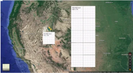
automa-Figure 14.Idea of Huge array for ultra-high energy cosmic ray observation using CRAFFT detector. Map data c⃝2018 Google
6 Future prospect
We proved the detection ability of ultra-high energy cos-mic ray air showers by CRAFFT detector. We propose a huge CRAFFT array for the next generation of cosmic ray observatory as shown in Fig. 14 Overlaid on the U.S. map. In order to clarify the origin of ultra-high energy cosmic ray, we need more detection area than ever. The detec-tion area of TA is∼700 km2. If we need 100 times more than TA, the detection area should be 70,000 km2which is shown in Fig. 14 as a left side square area . However, the duty cycle of FD is 10% of surface detector array. If we realize 100 times TA using only FDs such as CRAFFT, we need 700,000 km2. which is shown in Fig. 14 as a right side square area. If it is difficult to prepare such huge area at the same place as shown in Fig. 14, divided array can be distributed in any place, because the important things is total area.
If the target energy is above 1020eV, CRAFFT can de-tect air showers within∼25 km [14]. When we arrange the CRAFFT stations at intervals of 25 km over 700,000 km2, we need 900 CRAFFT stations. One CRAFFT station con-sists of 30 telescopes. Here, the F.O.V. of each telescope is assumed as 12◦. Under these assumption, total cost will be roughly $250,000,000.
7 Summary
We are developing a simple structure low cost fluores-cence detector for the next generation ultra-high energy cosmic ray observation named as Cosmic Ray Air Fluo-rescence Fresnel lens Telescope (CRAFFT). We deployed four CRAFFT detectors at TA FD site, and performed test observation from 2017 Nov. 9 to Nov. 23. In this period, we operated CRAFFT in ten nights, and total observation
time is 63.5 hours. We finally succeeded to detect 10 ultra-high energy cosmic ray air shower events. we proved our detector can be used for the next generation cosmic ray observatory.
Acknowledgment
120
− −100 −80 −60 −40 −20 0
Azimuth angle [deg] 0
5 10 15 20 25 30 35 40
Elevation angle [deg]
FD00
FD01
FD02
FD03
FD04
FD05
FD06
FD07
FD08
FD09
FD10
FD11 #1 #3 #4
#2
Figure 15.The F.O.V. of each CRAFFT detector is shown as circle drawn over the F.O.V. of the TA FDs edge of which is shown as a solid line [15].
Table 1.The list of the components of CRAFFT detector and each cost.
Component Product Specification Cost/FD
Structure MIWA Anodized, Alminum frame 950
Fresnel lens NTKJ, CF1200-B 1.4 m2, f=1.2 m 370
UV trans. filter Hoya, UL330 ∼80%, 300-360 nm 3,00
PMT Hamamatsu, R5921 8 inch 2,000
FADC TokushuDenshiKairo, Cosmo-Z 80 MHz, 12 bit 290
Amplifier Lecroy, 612AM 1,000
HV CAEN, N1470R 8 kV, 3 mA 1,600
Total ($): 9,210
References
[1] R.U. Abbasiet al., ApJ Lett.790, L21 (2014) [2] P. Priviteraet al., UHECR2012 (2012)
[3] R.U. Abbasi et al., Astropart. Phys. 23, 157-174 (2005)
[4] R.U. Abbasiet al., Astropart. Phys.64, 49-62 (2015) [5] A. Aabet al., Physical Review D90, no.12, 122005
(2014)
[6] R.U. Abbasiet al., Proceedings of international sym-posium for Ultra-High Energy Cosmic Rays, 010016 (2016)
[7] H. Tokunoet al., NIM A676, 54-65 (2012)
[8] The Pierre Auger Collaboration, NIM A620, 227–251 (2010)
[9] D. Mandat et al., Journal of Instrumentation 12, T07001 (2017)
[10] M. Casolino, Proceedings of the 35th International Cosmic Ray Conference, 370 (2017)
[11] P. Klimov et al. Proceedings of the 35th International Cosmic Ray Conference, 1098 (2017)
[12] A.V. Olinto et al., Proceedings of the 35th Interna-tional Cosmic Ray Conference, 542 (2017)
[13] A. Okumuraet al., Astroparticle Physics76, 38–47
![Figure 1. Hotspot in the arrival direction of UHECRs reportedby TA. [1]](https://thumb-us.123doks.com/thumbv2/123dok_us/8123268.1353486/1.595.325.515.533.637/figure-hotspot-arrival-direction-uhecrs-reportedby-ta.webp)