Available Online atwww.ijcsmc.com
International Journal of Computer Science and Mobile Computing
A Monthly Journal of Computer Science and Information Technology
ISSN 2320–088X
IJCSMC, Vol. 2, Issue. 10, October 2013, pg.14 – 29
RESEARCH ARTICLE
TIME SYNCHRONIZATION OF NODES
USING GENETIC ALGORITHM IN
WIRELESS SENSOR NETWORKS
Baljinder Kaur Amandeep Kaur
Research Scholar M.Tech (CSE) A.P, Dept. of computer sciences Sri Guru Granth Sahib World University (FGS) Sri Guru Granth Sahib World University (FGS)
[email protected] [email protected]
ABSTRACT:
Wireless sensor network has been a field where node synchronization has been a huge problem from decades to successfully transmit the data from source to destination there have been many research works about time synchronization in Wireless sensor network in the literature and so many methods and protocols are proposed. Many applications of sensor networks required local clocks to be synchronized for precision but different sensor network required different properties. In this paper we proposed a new algorithm in time synchronization which is Genetic Algorithm opt Routing algorithm (GAOR). The problem has been sorted up to a great extent using the global clock concept in which each local clock gets synchronized with the global clock so that the active and sleep mode of nodes does not affect the transmission but it consumes a lot of energy and time .in our work ,we have tried to solve this problem using genetic algorithm as if the current node gets a sleep mode of the upcoming mode ,it select another node on the basis of time consumption .this particular approach reduces the bit errors rate and the end to end delay, power utilization and other parameters also.
Keywords: Wireless sensor network; Time synchronization; Local clock; Global clock
1. INTRODUCTION
requirements and characteristics. The sensor networks can be used in a vast variety of fields like military environment, disaster management, habitat monitoring, medical and health care, industrial fields, home networks, detecting chemical, biological, radiological, nuclear, and explosive material etc [1]. Structure and topology of WSN can vary from simple star network to an advanced multi-hop wireless mesh network. Power constraints, limited hardware, decreased reliability, and a typically higher density and number of failure nodes are few of the problems that have to be considered when developing protocols for use in sensor networks [2].
Figure 1 shows a typical simple wireless sensor network. As can be seen, a complete wireless sensor network usually consists of one or more base stations (or gateway), a number of sensor nodes, and the end user. Sensor nodes are used to measure physical quantities such as temperature, position, humidity, pressure etc. The output of those sensor nodes are wirelessly transmitted to the base station (or gateway) for data collection, analysis, and logging. End users may also be able to receive and manage the data from the sensor via a website from long-distance or applications in console terminal. However due to the associated cost, time and complexity involved in implementation of such networks, developers prefer to have first-hand information on feasibility and reflectivity crucial to the implementation of the system prior to the hardware implementation[2].
Figure 1: A Simple Wireless Sensor Networks [2]
2. Time Synchronization in WSNs
In the other words Time synchronization algorithms provide a mechanism to synchronize the local clocks of the nodes in the network, to a global clock or relative to each other[3].Time synchronization plays a very important role because it allows the entire system to cooperate and function as a group. It is particularly important for a many of tasks such as synchronizing event detection, data fusion, and coordinating wake and sleep cycles. Due to its importance, the problem of time synchronization has been around for a long time. Many distributed applications running on WSNs need precise synchronization of the clocks among all nodes to have a consistent view of the global time. Each node runs on its own local clock and sends (receives) packets to (from) other nodes at sampling rate of its own clock. Also, to conserve the power, the nodes can enter the sleep mode after sending/receiving the packet and wakeup just before its time for another packet. If the clocks are not synchronized, the nodes can miss the packets sent by other nodes. As an alternative, the slave can have a guard time added to their wakeup time to remain active longer before going into sleep mode. This however increases the power consumption. So it’s imperative that the nodes maintain accurate time with respect to the global clock. [4]
The three basic methods of synchronization available in wireless sensor networks are:
1. Relative Ordering: In this method, the synchronization is on the order of messages or events. Here, clocks are not synchronized but just the order is maintained.
2. Relative Timing: In this method, a node keeps information about its drift and offset in correspondence to neighboring nodes. Thus, nodes have an ability to synchronize to its neighboring nodes.
3. Global Synchronization: In this method, there is a global timescale. All the network nodes to synchronize to this global clock.[2]
3. RELATED WORK:
Different time synchronization protocols have already been designed keeping in view various parameters such as accuracy, scalability, energy efficiency, errors and fault tolerance. Following are various existing synchronization protocols.
Traditional Time Synchronization (TTS): Network time protocol (NTP) is the traditional synchronization method which worked only in wired network. It’s also known as Two-way message exchange in which messages are exchanged between a pair of nods, In order to obtain a definitive relation between the two clocks with a single message exchange, two basic assumptions need to be made.
1. The offset between the clocks is constant in the small time period during the message exchange.
2. The propagation delay is the same in both directions [3].
Reference Broadcast Synchronization (RBS): Elson, Girod and Estrin proposed Reference Broadcast Synchronization (RBS) for sensor network and it is a receiver to receiver synchronization. A third party will broadcast a beacon to all the receivers. The receivers will compare their clocks to one another to calculate their relative phase offsets and transmit the recorded times to each other. The time of reference is based on when the nodes receive the beacon. Since the time synchronization protocol is receiver to receiver synchronization, the sender can be removed from the critical path. The simplest form of RBS is one broadcast beacon and two receivers. The timing packet will be broadcasted to the two receivers. The receivers will record when the packet was received according to their local clocks. Then, the two receivers will exchange their timing information and be able to calculate the offset. This is enough information to retain a local timescale. RBS differs from the traditional sender to receiver synchronization by using receiver to receiver synchronization. The reference beacon is broadcasted across all nodes. Once it is received, the receivers note their local time and then exchange timing information with their neighboring nodes. The nodes will then be able to calculate their offset.[3,9]
Figure 3 - Comparison of a traditional synchronization system with RBS [3]
phase, the synchronization phase begins at the root node and propagates through the network[10].
Flooded Time synchronization Protocol (FTSP): The FTSP was designed at Vandebuilt University and implemented using Berkeley Mica2 motes [3]. FTSP is sender to receiver synchronization. This protocol is similar to TPSN, but it improves on the disadvantages to TPSN. It is similar in the fact that it has a structure with a root node and that all nodes are synchronized to the root.
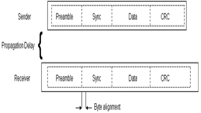
In the FTSP, the nodes can form a mesh network where each node sends out time sync message to every other node, or they can form a star network where only one node at a time acts as a master and all the other nodes act as slaves. The master node periodically sends out a time sync message. All the slaves in the network receive this message and synchronize their local clocks to the master clock. If the slaves’ clock is off only by a constant, ideally one packet would be necessary to get synchronized with the global clock. But, various issue like temperature, aging produce a drift in the slave’s clock that needs to be periodically synchronized to the master clock.[1]
Figure 4 - Data packets transmitted with FTSP
Traditional two-way messaging is used to collect data points, which are used to apply tight bounds on relative drift and relative offset between two nodes. To create data point using two nodes; 1 and 2, node 1 sends a probe message with timestamp to. Node 2 timestamps the received message with tb and sends back an acknowledgment to node 1, immediately or after sometime, which timestamps this acknowledgment with tr [3]. Fig.5 shows the previous described sequence.
Figure 5. Probe message exchange of Tiny-Sync and Mini-Sync [12]
Lightweight Tree -Based Synchronization: Some wireless sensor networks need a precision in order of micro seconds, while others need it in order of milliseconds. The algorithms proposed in deal with this fact by assuming that the precision to be achieved is given, and hence, the complexity and computational time depend on this given value.
First algorithm consists of two phases; a spanning tree is constructed in phase one. Then a sender to receiver synchronization is done along the n-1 edges of the spanning tree in phase two. In this centralized algorithm, all nodes synchronize to a central one, called sink or root node. Also, it sets the total time to synchronize the whole network
In the second algorithm, nodes decide when they need to be synchronized based on their distance from the reference node, clock drift, and the required precision. So, any node in the network can initiate the synchronization phase with a reference point, and all nodes along the path to that reference point must be synchronized first. As some nodes do not need to be synchronized all the times, this algorithm removes the overhead of unnecessary synchronization by allowing nodes to make decisions. Aggregation of synchronization requests is used to make this algorithm more efficient. Before the node sends synchronization requests, it checks with its neighbors to see if any request is pending, if any, it will add its request to the pending one, so the path will be synchronized only once. In suggested algorithm divides the whole network into sub trees. In each sub tree, children synchronize to their parent or root node. Then, all parents synchronize with each other [3-14].
traditional synchronization schemes, for NTP. In these local clocks of the sensor nodes should normally run unsynchronized in their own pace and should synchronize only when necessary. ). Post-facto synchronization can also be termed as reactive synchronization, while the traditional schemes are proactive, requiring the clocks of sensor nodes to be synchronized before an event of interest occurs[15].
Time-Diffusion-Synchronization Protocol: The time – diffusion protocol (TDP) is a synchronization protocol that maintains an equilibrium time throughout the network, allowing only a small deviation from the equilibrium. The deviation tolerance can be adjusted based on the specific sensor network application. TDP has a two type of periods in long term. These are active and inactive periods. At every d seconds during the active period, some nodes are elected
as master nodes that broadcast timing information to their neighbors at every μ seconds. Nodes
receiving timing information from the master nodes self - determine to become diffused leader nodes that further broadcast the timing information to their neighbors[3].
Other exiting time Synchronization Protocol: In wireless sensor networks, the main problem for time synchronization protocols is the send time, access time, propagation time, and the receive time. We eliminates these by using RBS, TPSN, and FTSP time synchronization protocols and it gives better results in form of accuracy and effectiveness. But today to gain more better results we have many new time synchronization protocols . These time synchronization protocols used bsic idea from RBS, TPSN, and FTSP. So these are some other popular algorithms Rate adaptive time synchronization (RATS) by Ganeriwal et al, Asynchronous diffusion protocol proposed by Li and Rus, Reachback fi refl y algorithm (RFA), Adaptive - rate synchronization protocol (ARSP) etc.
4. Problem Definition
In this paper we proposed new algorithm which is Genetic algorithm opt Routing(GAOR). It is based on global time from clock synchronization approach. In time synchronization we used clock concept for communication and to transfer data between different nodes in wireless sensor networks. In this
Concept any node present in the network is either on active mode or sleep mode. If node on active mode then its avail to transfer packet to next node to reach the destination. If node on sleep mode then data packet is lost and it wait for time tll node on active mode to transfer data packet. so its increase the time delay during transmission, mean error, packet loss and consume too much energy.
5. Genetic Algorithm Opting Routing (GAOR)
symmetric properties of bi-directional links in sensor-networks to remove all the sources of error. The number of receivers lying within a single broadcast domain limits the set of receivers synchronized.
In other words we can say that during transmission if the current node gets an active mode then it’s able to transfer data packets. It does not required GAOR algorithm for transmission. if the current node gets a sleep mode of the upcoming node then it select another suitable node on the basis of time consumption. To select another node it used another path for transmission. To select another path it using a GAOR algorithm. In this algorithm it uses a routing method. It prepared a list of path by which we reach to destination but we choose best path in which we reach to destination easily and consume less time and energy. This particular approach reduces the bit error rate and the end to end delay and other parameters.
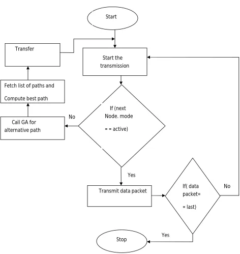
5.1 Algorithm
In GAOR algorithm we have following steps: 1. Node start the transmission
2. If(next node. mode = = active) 3. Then transmit data
4. If( data packet .count = = last) 5. Then stop
6. Otherwise call step 1
7. Else call GA for Alternative Path 8. GA fetch list of paths
5.2 Scheduling Activity
Figure 6 Activity Diagram for GAOR Algorithm
In the above Figure 3.1 we show all the steps which are following in Genetic Algorithm Opting Routing. If next coming node on active node then transmit data packet otherwise call GAOR algorithm to select best path to transmit data packet.
Start
Start the transmission
If (next Node. mode
= = active)
Transmit data packet Call GA for
alternative path Fetch list of paths and
Compute best path Transfer
If( data packet=
= last)
Stop Yes
Yes No
5.3 Algorithm Description:
In this section we present a Genetic Algorithm opt Routing algorithm. The algorithm mainly depends on two modes. These modes are as following:
(1) node on active mode
(2) node on sleep mode
In clock synchronization the active and sleep mode of nodes does not affect the transmission but it consumes a lot of energy and time. We have tried to solve this problem using genetic algorithm as if the current node gets a sleep mode of the upcoming mode, it select another node on the basis of time consumption. By using GAOR algorithm it prepared a list of other nodes by which we can reached to the destination node. In the last it selects nodes by which we reach to the destination. So it selects the final nodes through which data packet are transmitted. So in this manner we obtain successful transmission. If our data packet equal to zero than it stops working else it again starts the process from the starting and check whether current node is on active mode or on sleep mode. If current node on sleep mode than it call GAOR algorithm for data transmission.
6. Simulation Environment
The simulations were conducted using MATLAB7.5.0 (R2007b). As for the number of sensor nodes, 50 nodes are used. The performance evaluation includes two parts: Time consumption, errors and synchronization delay. The sensors are simulated to deploy over a square sized area of l00m x l00m with adjustable communication range and fixed sensing range. We have compared the performance of clock synchronization with Genetic Algorithm opt Routing synchronization protocols based on above energy analysis. We used different values of parameters like number of nods 50, network grid of 100 by 100 m, position of base station 50 by 175m. During transmission it transmit 500bits in a data packet. The basic parameters used are listed in Table 4.1.
Table 1 Show the simulation parameters
Parameter Value
Number of nodes 50
Network grid 100 by 100 m
Base station position 50 by 175 m
Size of data packet 500 bits
In this simulation, the total time is obtained in seconds. The purpose of this Simulation is to analyze and compare the performance difference between two synchronization algorithms “Clock synchronization algorithm”, and proposed” Genetic algorithm opt Routing algorithm”.
7. RESULTS
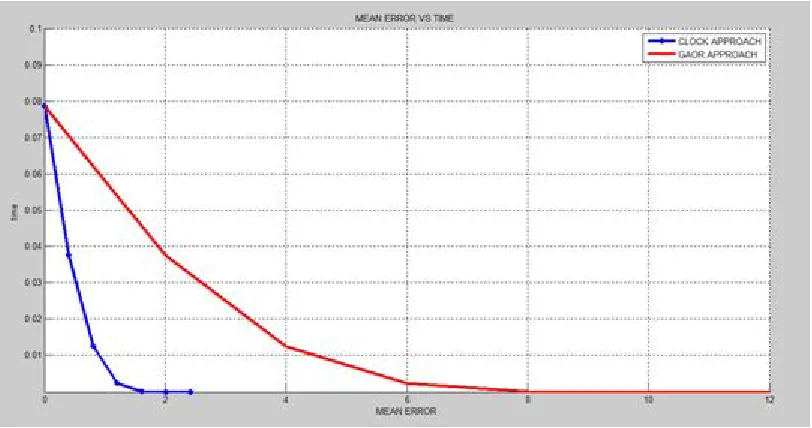
To measure the performance of the GAOR algorithm in wireless sensor network for this purpose a reference packet sender node is deployed into the first position and the other sensor nodes are spread across the entire network randomly or uniformly. As the performance metrics, the number of Mean errors, End to End delay, power consumption and the Packet errors in time synchronization for all sensor nodes are considered. The figure 4.1 shows the number of Errors according to Time increase in the number of sensor nodes for GAOR algorithm and Clock synchronization.
Figure 7 Time vs Mean Error
The above graph is drawn by result of Clock synchronization and GAOR algorithm. The table 4.2 shows the number of mean errors at different time.
Mean Square Error
Time(GAOR algorithm)
Time(clock synchronization algorithm)
0 0.079 0.079
2 0.035 0.039
4 0.01 0.014
6 0.002 0.003
8 0 0
10 0 0
12 0 0
Above table 4.2 shows the Mean square Errors at different time. Mean errors are computed by total number of errors in total number of packets. Mean square errors is 0 at time interval of 0.079 Sec like this Mean square Errors is 2 at time interval of 0.035sec in GAOR algorithm and 0.079 sec in clock synchronization algorithm. We can said that Mean square Errors is increase continuously when time interval is increase but there is less Mean square Errors when time is increases in GAOR algorithm instead of previous clock synchronization algorithm in Time Synchronization for wireless sensor network.
In next parameter we calculate the End to End delay which depends on the time. It is the delay which is calculated when the data packet is transmitted from one end to and receiving to the other end but not at the expected time. The time difference which occurs to one node to another is called End to End Delay. It occurs due to these reasons. If the start node and next node is not synchronized well or if the modulation done with in packet is not appropriate. Figure 4.2 shows the Mean Errors at different levels End to End delay.
Figure 8 Mean Errors at different levels of End to End Delay
Below Table 4.3 shows the different mean errors at different levels of End to End delay. We face less mean errors when end to end delay is increases. Results of our proposed algorithm are much better than previous clock synchronization algorithm.
End To End Delay Mean Error (GAOR algorithm)
Mean Error (clock synchronization algorithm)
0 0.0051 0.032
2 0.0049 0.026
4 0.0035 0.021
6 0.003 0.016
8 0.002 0.012
10 0.001 0.0075
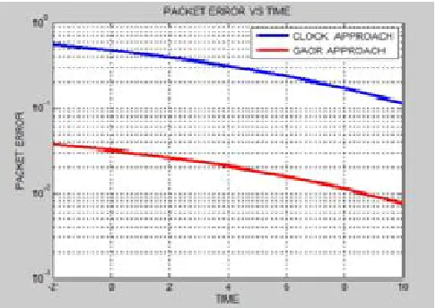
Now our next parameter is Packet Error which shows errors in particular number of packets. It is the errors which can be determine when the entire data packet can be receiving end. It occurs if the transmitted bits in the packet are not similar to the bits which is received. Figure shows the results for packet error.
Figure 9 Show Packet Errors at different levels of Time
In above figure 4.3 we show the comparison of both algorithms on the basis of packet error at different level of time. At the time interval of 0sec we have 0.05 packet error in GAOR algorithm and 0.07 packet errors in clock synchronization algorithm like this at 2 sec we have 0.035 and 0.06 so on. it shows that results are much better in our proposed algorithm. Below table 4.4 will show different packet errors at different interval of time.
Time Packet Error
(GAOR algorithm)
Packet Error (clock sync algorithm)
0 0.05 0.7
2 0.035 0.6
4 0.03 0.5
6 0.02 0.45
8 0.015 0.35
10 0.009 0.16
Table 4 Packet Errors at different level of Time
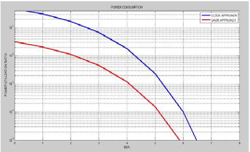
Figure 10 Power utilization at different level of BER
We also explain this concept in detail with the help of table 4.5 which is taken from graph results. In which we have more power utilization when we have less bit error rate.
APPROACH BER(MAX) POWER
UTILIZATION(AVG)
CLOCK 6.7 69 %
GAOR 6 83 %
Table 5 show Power utilization
So above we compare parameters of our proposed approach GAOR with previous approach clock synchronization. In above mention parameters gives us much better result by using proposed approach GAOR. These results show with the help of graphs and tables.
References
______________________________________________________________________________
[1] Akyildiz et al , “Technology Review “,Business Week ,2003
[2] Neha Singh, Prof.Rajeshwar Lal Dua, and Vinita Mathur, “Wireless Sensor Networks: Architecture, Protocols, Simulator Tool,” International Journal of Advanced Research in Computer Science and Software Engineering, vol.2, iss.5, May 2012.
[3]Harsh Sundani, Haoyue Li, Vijay K. Devabhaktuni, Mansoor Alam, and Prabir Bhattacharya,“Wireless Sensor Network Simulators a Survey and Comparisons,” International Journal of Computer Networks (IJCN), vol.2, iss.5, pp. 249-265, Feb. 2011.
[4] I. F. Akyildiz , W. Su , Y. Sankarasubramaniam , and E. Cayirci , “ Wireless sensor networks: A survey ”, Computer Networks , vol. 38 , no. 4 , Mar. 2002 , pp. 393 – 422 .
[5] C. Herring and S. Kaplan , “ Component - based software systems for smart environments” , IEEE Personal Communications , vol. 7 , no. 5 , Oct. 2000 , pp. 60 – 61 .
[6] Holger, K., Willig A. . “Protocols and Architectures for Wireless Sensor Networks. “ ,IEEE. (2003). Part 15.4
[7] F. Zhao and L. Guibas , “ Wireless Sensor Networks: An Information Processing Approach “, Morgan Kaufmann Publishers , San Francisco, CA , 2004 .
[8] Culler, D., Hong, W. , “Wireless Sensor Networks.” Communication of the ACM, 2004. 47, 30-33. [9]. M Maroti, B. Kusy, G. Simon, and A. Ledeczi, "The Flooding Time Synchronization Protocol," in Proceedings of the 2nd International Conference on Embedded Network Sensor Systems (SenSys ’04), pp. 39-49.
[10]. Dennis Cox, Emil Jovanov, Aleksandar Milenkovic, “Time Synchronization for ZigBee Networks” [11]. Fikret Sivrikaya and Bulent Yener, “Time Synchronization in Sensor Networks: A Survey”, IEEE Network, 18(4): Pages : 45-50, August 2004
[12]. Matthias Keller, Jan Beutel, Andreas Meier, Roman Lim, and Lothar Thiele. “Learning from sensor network data”, In SenSys ’09: Proceedings of the 7th ACM Conference on Embedded Networked Sensor Systems, pages 383–384, New York, NY, USA, 2009. ACM.
[13] Timing Synchronization in Sensor Networks, http://www.ee.ucla.edu/~saurabh/time_synchronization/ [14]. Characterizing Time Synchronization,
http://www.circlemud.org/~jelson/writings/timesync/node2.html
[15]. S. Ping, “Delay Measurement Time Synchronization For Wireless Sensor Networks,” Technical Report, Intel Research Berkeley Lab, 2003
[16]. J. Elson, L. Girod, and D. Estrin, “Fine-Grained Time Synchronization using Reference Broadcasts," Proceedings of the Fifth Symposium on Operating Systems Design and Implementation (OSDI 2002), Boston, MA, December 2002.
[17]. Hyojung Lee, Wonpil Yu, Youngmi Kwon, “Efficien RBS in Sensor Networks, “ in IEEE ITNG”, 2006.
[18] S. Ganeriwal, R. Kumar, M. Srivastava,“Timing Sync Protocol for Sensor Networks,” ACM SenSys ’03, 2003.
[19] Feng Wang; Jiangchuan Liu, “RBS: A ReliablevBroadcast services for large – Scale Low Duty-Cycled Wireless Sensor Networks,” IEEE International Conference on Communications,2008
[20] S. Ganeriwal, R. Kumar, and M. Srivastava, “Timing Sync Protocol for Sensor Networks," ACM SenSys, Los Angeles, November 2003.
[22]. Mingxia Xu, Minjian Zhao, Shiju Li, “Lightweight and Energy EfficientTime Synchronization for Sensor Network”, IEEE International Conference on Wireless Communications, Networking and Mobile Computing, Volume 2: Pages 947-950., Sept 2005.
[23] Elson, J.; Girod, L.; Estrin, D., “ Fine-grained network time synchronization using reference
broadcasts.” ,the Fifth Symposium on Operating System Design and Implementation, Boston, MA, USA, Dec. 2002.
[24] Sundararaman, B. et al.,” Clock synchronization for wireless sensor networks: a survey”,. Ad Hoc Netw. 2005, 3, 281-323.
[25] Ganeriwal, S.; Kumar, R; Srivastava, M.B. , “Timing-sync protocol for sensor networks” ,1st international conference on Embedded networked sensor systems, Los Angeles, CA, USA, Nov. 2003; pp. 138-149.
[26] Y. Wu, Q. Chaudhari and E. Serpedin, “Clock Synchronization of Wireless Sensor Networks,” IEEE Signal Processing Magazine, 2010.
[27] S. M. Lasassmeh and J. M. Conrad, “Time Synchronization in Wireless Sensor Networks: A Survey,” IEEE, 2010.
[28] J. Feng, R. W. Pazzi and A. Boukerche, “The Impact of Discrete Clock on Time Synchronization in Wireless Sensor Networks,” The 9th IEEE International Workshop on Wireless Local Networks , 20-23 October
2009.
[29] Aamir Mahmood, Riku Jantti ,“Time Synchronization Accuracy in Real-time Wireless Sensor Networks”, IEEE 9th Malaysia International Conference on Communications,2009
[30] Qiang Gao, Baomin Xu ,“Time Synchronization Improvement for Wireless Sensor Networks”, 1st International Symposium on Pervasive Computing and Applications,2006
[31] Liming He, Liming He, “A Novel Time Synchronization Scheme in Wireless Sensor Networks”, IEEE journal,2006
[32] Kyoung-Lae Noh, Erchin Serpedin, and Khalid Qaraqe, “A New Approach for Time Synchronization in Wireless Sensor Networks: Pairwise Broadcast Synchronization”, IEEE TRANSACTIONS ON WIRELESS COMMUNICATIONS, VOL. 7, NO. 9, SEPTEMBER 2008
[33] Stefano Severi, Davide Dardari, “Performance Limits of Time Synchronization in Wireless Sensor Networks”, IEEE Communications Society,2008
[34] Wanrong Wu, Qianping Wang, Wei Wang, Yu-e Su, Yuan An, “Energy-Efficent Time Synchronization Algorithm for Wireless Sensor Networks”,IEEE journal,2010
[35] Shushant Jain, Yogesh Sharma, “ Optimal Performance Reference Broadcast Synchronization (OPRBS) for Time Synchronization in Wireless Sensor Networks”, International Conference on Computer, Communication and Electrical Technology – ICCCET, 2011
[36] Gopal Chand Gautam, T. P. Sharma, Vivek Katiyar and Anil Kumar, “Time Synchronization Protocol for Wireless Sensor Networking using Clustering ”, IEEE-International Conference on Recent Trends in Information Technology,2011
[37] Gyula Simon, “ Efficent time- synchronization in ring topology wireless sensor networks.”, IEEE journal,2012
![Figure 3 - Comparison of a traditional synchronization system with RBS [3]](https://thumb-us.123doks.com/thumbv2/123dok_us/7730456.1265524/4.612.200.410.325.513/figure-comparison-traditional-synchronization-rbs.webp)
![Figure 5. Probe message exchange of Tiny-Sync and Mini-Sync [12]](https://thumb-us.123doks.com/thumbv2/123dok_us/7730456.1265524/6.612.155.449.175.360/figure-probe-message-exchange-tiny-sync-mini-sync.webp)