International Journal of Research
Available at https://edupediapublications.org/journalse-ISSN: 2348-6848 p-ISSN: 2348-795X Volume 06 Issue 06
May 2019
Available online:https://edupediapublications.org/journals/index.php/IJR/ P a g e | 473
Optical communication 10gbps Ethernet speed
Author Name:- Dr.Nitish Meena
Department Name:- Associate professor in Electronics and Communication College Name:- Advait Vedanta Institute of Technology,Jaipur E-mail:- [email protected]
Abstract:-
Ethernet LAN topology is presently the most mutual network design. Ethernet topologies are commonly bus and/or bus-star, topologies. Ethernet setups are passive, which means Ethernet hubs do not recycle or modify the signal sent by the involved devices. Ethernet technology customs transmission topology with base band signaling and a control method known as Carrier Sense Multiple Access/Collision Detection (CSMA/CD) to transfer data. The IEEE 802.3 standard describes Ethernet procedures for (Open Systems Interconnect) OSI’s Media Access Control (MAC) sub layer and physical level network characteristics. The IEEE802.2 standard describes protocols for the Logical Link Control (LLC) sub layer. A solid appreciative of Ethernet basics is necessary for all network persons.Keywords:-
Wired LAN, Wireless LAN, Quality of service (QoS), OPNET.Introduction:-
A Communication may be recognized through a collection of different media, general choices include copper cables and fiber optics. Excluding for the material connection a diversity of principles is used to allow an operational communication channel.these principles are required for hardware configurations such as bit rate and signal amplitudes, as well as to describe the sense of the signal array that is to be approved over the channel. Ethernet is a set of such values used to explain a well-known and used structure. This group defines a range of values about different ways of signaling over different mediums. The principles are used to encode an array of bits to transmit table signals. A order of bits or information is called a frame which is illustrated in Figure1.1. The duration/Type field defines the quantity of data or if the data should being terpreted according to a different protocol such as IP [2].
International Journal of Research
Available at https://edupediapublications.org/journalse-ISSN: 2348-6848 p-ISSN: 2348-795X Volume 06 Issue 06
May 2019
Available online:https://edupediapublications.org/journals/index.php/IJR/ P a g e | 474
Figure 1.1: The most common Ethernet
Frame format
Ethernet Configuration and
Communication:-
Ethernet Configuration
Ethernet broadcast topology in communication and that may be designed as a physical star and physical bus through logical bus for hardware configuration.
Figure 1.2:-Ethernet Physical Bus Topology
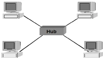
The physical star using a logical bus is generated with the use of a hub or concentrator.
Figure 1.3:-Ethernet Physical Star/Logical
Bus Topology
Ethernet
Communication:-Communication procedures for Ethernet networks in clued the data link and physical layers of the OSI model. This lesson contracts mostly by the data-link layer, which is subdivided into a Media Access Control layer (MACL) and a Logical Link Control layer (LLCL).
International Journal of Research
Available at https://edupediapublications.org/journalse-ISSN: 2348-6848 p-ISSN: 2348-795X Volume 06 Issue 06
May 2019
Available online:https://edupediapublications.org/journals/index.php/IJR/ P a g e | 475
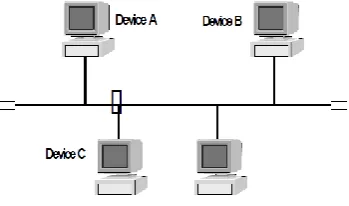
Various Accesses means that totally devices have equal access to the network. Then Ethernet is contention-based, equal access to the network for totally is ensured. No device has priority over others, nor can it lock out some device linked to the network. Information can be transferred at any time by any device. All devices on the network collect the transmission and checked the framed packet’s destination or target address. If the destination or target address compares the device’s address, the device receives the data. If the address does not match, the device basically ignores the transmission.
Figure 1.4 Ethernet Collisions
Collision Detection means that a transfer device can “detect” synchronized transmission attempts. When two or more than two devices try to transfer data at the same time, the signals is crash. The example above shows devices A, B, and C transfer signals at the same time, and a collision occurs. When this happens, every device then sends a jam signal, known as a carrier, to alert all other devices that an impact has occurred.
All devices then go back into off conduction and delay a random quantity of time before trying to retransmit data. The random time provision checks simultaneous retransmissions. Totally devices on the same Carrier Logic Various Access/Collision Detection wire section are part of the same accident domain. An accident domain is described as those devices that share CSMA/CD of the same cable. Two or more than two accident domains are linked organized through an internetworking device such as a router, switch or bridge. Through the use of internetworking devices, large networks are created which comprise multiple accident domains.
International Journal of Research
Available at https://edupediapublications.org/journalse-ISSN: 2348-6848 p-ISSN: 2348-795X Volume 06 Issue 06
May 2019
Available online:https://edupediapublications.org/journals/index.php/IJR/ P a g e | 476
it. The need is to keep transportation and impacts to a single accident domain whenever thinkable. Collision domains are also named segments in Ethernet.
Data communicated from one user to another user on the similar collision domain will not disturb any additional collision domains. This agrees to each impact domain to carry on transmitting with no disturb on every other except when a device requirements to conversation to a user on extra collision domain. When this is compulsory, the edge must be conducted through one or more than one internetworking user to touch its target. Every internetworking user must agree the edge to pass. As the edge touches every one collision domain the port of the internetworking user must struggle for the right to communicate permitting to the rules of CSMA/CD.
Single Collision domain 1
(Segment 1)
EBridge
(Internetwork Device)
Single Collision domain #2
(Segment 2)
Figure 1.5:-Ethernet Collision Domain
Carrier Ethernet:-
The main important phase is defining Carrier Ethernet, what it exactly means and accepting the justification for this meaning. Also as important, is an established reference background—the framework in which this description applies, and the compulsory components that make up this framework. In so doing, a mutual and reliable understanding as well as a “language” to define Carrier Ethernet services is delivered. With this as the source, the qualities are deliberated in superior detail (note: in the framework of this volume, only a necessary summary can be reasonably delivered), with careful conferences in a few zones that are deemed especially serious to allowing Carrier Ethernet.
International Journal of Research
Available at https://edupediapublications.org/journalse-ISSN: 2348-6848 p-ISSN: 2348-795X Volume 06 Issue 06
May 2019
Available online:https://edupediapublications.org/journals/index.php/IJR/ P a g e | 477
Carrier Ethernet fundamentally involves the deterministic and other facility transfer aspects for homogeneous Ethernet services. This idea is key because it highpoints the focus on homogeneous Ethernet services and the exact characteristics of such facilities and not essentially the original transport substructure itself.
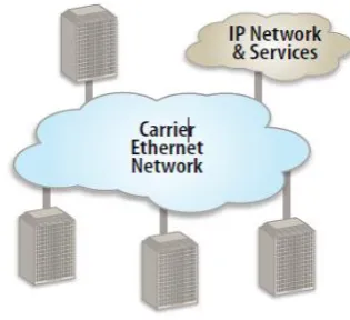
Figure 1.6:-Carrier Ethernet Network
Carrier Ethernet addresses the restrictions of donation skill by providing elastic bandwidth scalability. Formerly Ethernet service is arranged. Bandwidth can be sum basically through remote provisioning up to the Ethernet port speed. This allows the facility supplier to sell, or creativity to organize, the quantity of bandwidth subscribers really requirement, rather than making them to purchase a specific quantity ofbandwidth verbalized by the legacy technology. In calculation, it is not compulsory to send a facility specialist to the user premises. This produces extra Op Ex savings when related to legacy
services.
With Carrier Ethernet, user can now use the same, wellassumed Ethernet skill for their LAN, MAN and WAN networks.
High-Speed
Optical
Networking
with
Ethernet:-The major focus of this thesis is establishing high-speed connectivity of workstations more optical fiber. The networking of these workstations is approved out through broadcast of 'speedy Ethernet' data at 100 Mbps. There are commercially accessible fiber-transceivers that give high frequency Ethernet connectivity at 100 Mbps, but this is disappointing from the point of view of the very lofty costs include.
International Journal of Research
Available at https://edupediapublications.org/journalse-ISSN: 2348-6848 p-ISSN: 2348-795X Volume 06 Issue 06
May 2019
Available online:https://edupediapublications.org/journals/index.php/IJR/ P a g e | 478
Multiplexing (WDM) network more 6.2 km of single mode fiber at a data speed of 2.5 Gb/s. This simulates high-speed Ethernet fiber optic broadcast at 2.5 Gb/s which is an OC-48 SONET standard.
This provides an extremely reasonably priced solution for broadcast of ‘Fast Ethernet' over fiber as opposite to the high-speed connectivity achieved by using the commercially accessible exclusive fiber transceivers with fitted lasers and photo receivers. A four-wavelength Division Multiplexing(WDM) system was realized effectively at 2.5 Gb/s more 6.2 kilometers of single mode fiber with a bit error rate of 10"^. This guarantees real-time broadcast of Ethernet information at the equal rate. at present the maximum speed of receiving the information out of a computer electrically is 100 Mbps. The Gigabit Ethernet network interface certificate can output information at 1000 Mbps, but this runs on fiber openly. So, if data can be obtained at 1000 Mbps (or upper to 2.5Gb/s) electrically, the same set of experiments can be performed delivering four wavelength Division Multiplexing(WDM) network transmitting Ethernet signals at 2.5 Gb/s. The arithmetical model discussed in this thesis, extrapolates the four-wavelength Division Multiplexing (WDM) network to eight wavelength Division Multiplexing (WDM) network. The simulation of this representation have exposed that even for a busy network the successful broadcast efficiency is 64 %.With these arithmetical simulations and investigational results, this
thesis can be used as a basis for successfully structure an eight-wavelength Division Multiplexing (WDM) network approximately Texas Tech University campus thus networking each departments.
The
Vertical-Cavity
Surface
Emitting
Laser
(VCSEL)
and
Electrical Access Contribution:-
By presenting an general idea of electrical comparable circuit modeling and description for the VCSEL chip, based on the diffusion parameters, an summary of the VCSEL performances set in order to give a good information of this device performance in different operation modes and avoid its insufficient utilization (Risson setal., 2003), (Perchouxetal., 2008), (Bacouetal., 2009).
Suitable to the emergence of the small coldness optical communication, the VCSELs have become, in the past ten years, a key part of the optical interconnections. The current succeeding the VCSEL skill makes this laser diode capable for different application fields and spirited with admiration to the Edge-Emitting laser (EEL) and the Light Edge-Emitting Diode (LED)(provided that the laser presentation while charge the cost efficiency of the LED) (Koyama,2006),(Suematsu&Iga, 2008).
International Journal of Research
Available at https://edupediapublications.org/journalse-ISSN: 2348-6848 p-ISSN: 2348-795X Volume 06 Issue 06
May 2019
Available online:https://edupediapublications.org/journals/index.php/IJR/ P a g e | 479
by Prof. K. Iga (Iga et al., 1988) and its original commercialization at the finish of the 90’s, the VCSEL arrangement finds itself in a condition of stable development. Today, it covers a wide wavelength production range (from the blue-green group up to the infrared) that enables the custom of these apparatus in various application fields, not only in the small space digital communications (LAN, Avionic network (Ly et al., 2008),) but too in customer applications for example, laser mice,display systems, laser printers, , etc.
Everyone these applications can be made likely thanks to:
The perpendicular emission vertical to the semiconductor layers makes easier the assimilation (1D and 2D Array) according to the electrical covering constraints.
By combining the little size and the vertical production, this part responds to the principle of planarization provided that a high assimilation level.
The low quantity of the active layer (AL) due to the quantum wells (QW) involves a sub-milliamps threshold current and low electrical power utilization.
The VCSEL presents a short thermal confidence close to the room heat.
The sequential fabrication reduces the price and allows on-wafer test.
Due to its cylindrical geometry, the light-beam fractious part is round.
Figure.1.7. Comparison between Edge
Emitting laser (on the left) and VCSEL(on
the right)
International Journal of Research
Available at https://edupediapublications.org/journalse-ISSN: 2348-6848 p-ISSN: 2348-795X Volume 06 Issue 06
May 2019
Available online:https://edupediapublications.org/journals/index.php/IJR/ P a g e | 480
classification previous to the VCSEL operation (Bacouetal., 2010). Hence we propose to educate a chapter to the VCSEL skill that aims at give an impression of the advances, the physical performance, and its different structures counting the electrical admission regarding VCSELs.
Figure.1.8:- First structure proposal of
Surface Emitting laser
Ethernet Passive Optical Network:-
This document describes Ethernet inactive optical networks. Ethernet inactive optical system is an emerging local subscriber right to use structural design that combines low-cost point-to-multipoint fiber communications with Ethernet. EPONs are planned to take Ethernet frames at usual Ethernet rates. An EPON uses solo trunk thread that extends from a middle agency to an inactive optical splitter, which then fans out to several optical drop fibers linked to subscriber nodes. Other than the end terminating apparatus, no element in the system requires electrical power, therefore the
word inactive. Local carriers have long been involved in inactive optical networks for the profit they offer: minimum fiber communications and no powering necessity in the exterior place. With Ethernet now emerging as the procedure of option for transport IP transfer in metro and admission networks, EPON has emerged as a possible optimized structural design for fiber to the structure and fiber to the house.
International Journal of Research
Available at https://edupediapublications.org/journalse-ISSN: 2348-6848 p-ISSN: 2348-795X Volume 06 Issue 06
May 2019
Available online:https://edupediapublications.org/journals/index.php/IJR/ P a g e | 481
A passive optical network (PON) is a one point-to-another point, fiber to the premises network structural design in which unpowered visual splitters are used to allow a single optical fiber to serve multiple location, normally 16-128. A PON is a data link access skill that delivers information from a central office Optical Line Terminal (OLT) to customer premises positioned Optical Network Units (ONUs).A PON consists of an optical line terminal (OLT) at the service provider’s middle office and amount of optical network units (ONUs) close to end users. APON reduces the quantity of fiber and central office equipment necessary compared with point to point structural design. An inactive optical network is a shape of fiber-optic access network.
Ethernet structural design is based on the thought of linking multiple computers to a long cable, now and once more called the ether, thus forming a bus structure. Every computer is fixed within Ethernet adapter that includes a single 48-bit address for that computer. Every computer is connected to the ether through transceiver that forms a logical “T.” The transceiver receives Ethernet messages on the cable, looks at the address, and moreover passes the communication to its computer, if the address matches, or transmits it down the wire, if the address does not same.
An only (logical) Ethernet wire forms a local area network. Two LANs can be connected through so-called bridges. A bridge is a unique computer linked to two LANs. When it
receives a message, it determines which of the two networks the computer individual addressed is on and forwards the communication to the suitable network .
Compared to the conventional APON method, due to the wide operation of Ethernet technique, EPON is projected to get a lower cost to set up a structure. In addition, it is extra capable in network capability operation due to its minor control over head in every Ethernet edge than the overhead in every ATM cell. However, compared to APON, it may not be capable to support QoS for request services as well as ATM, as APON has an extra complicated QoS-supporting plan hereditary from the usual ATM networks .
In this paper Ethernet inactive optical network has been discussed. A short structural design of Ethernet has been set the past has been given. Ethernet inactive optical networks (EPONs), which symbolize the meeting of low-priced Ethernet equipment and low-priced fiber infrastructure, appear to be the best candidate for the next-generation access network. Future viewpoint of EPON has been specified and its current-status.
Network-edge Technology:-
International Journal of Research
Available at https://edupediapublications.org/journalse-ISSN: 2348-6848 p-ISSN: 2348-795X Volume 06 Issue 06
May 2019
Available online:https://edupediapublications.org/journals/index.php/IJR/ P a g e | 482
electrical interconnects reduce bandwidth quadratic ally with growing length and reduce bandwidth linearly with decrease cross-sectional region, due to the skin result of the inductive-capacitive (LC) limited lines [13]. An optical backplane will ease intrinsic problems linked to the aspect ratio of conductive appearance, as well as extrinsic problems general to electrical interconnects, such as broadcast loss, pre-emphasis necessities, active equalization, power use, signal diffusion, clock allocation, system management, protecting, capacitive separation, wave expression, crosstalk, wave reflection, and pin inductance. These shortcomings will crash the system in special ways: the signal power is improved to overcome the broadcast loss, which can reach 50dB/M on FR-4. This power augment, besides lowering the competence, generates heat, which requires advanced cooling require. Capacitive
effect
on the indication plane cause signal scattering which increase the inter-symbol interference (ISI). The lack of protecting can product in crosstalk between two channels, but the addition of shielding increases the size density. These electrical are linked difficulties creating high-bandwidth transmissions impractical. To achieve throughputs of 100Gbps it is compulsory to use an optical backplane with multiple
similar
channels. By using optical switching mechanisms, conversions between the electrical and optical domains can be avoided to advance reduce delay. An optical backplane will need the combination of lasers, optical waveguides, and detectors. Theincorporation of this element is not minor and improving the combination efficiency and dependability is a constant research effort. A major complexity has been the optical alignment of the three mechanisms, which is exacerbated by the fact that together a VCSEL and a standard PIN PD are vertical-surface emitting and screening devices, while waveguides are normally placed parallel. A common attempt at a result has been to think in terms of conventional component mixing and to bring together lenses and micro-mirrors to collimate and bend the light path. The use of 45o micro-mirrors has been done constantly [16][17][18][19][21][23]; other techniques comprise the use of coiled mirrors [20]. For optical interconnects to develop into a skill, the integration procedure must display optical arrangement among hundreds of optical channels in a rationally simple and routine method. For the skill to become an item for consumption, the integration process has to become collection producible and reveal a reliable performance benefit at aggressive cost and lower the power dissipation as much as likely with existing products.
International Journal of Research
Available at https://edupediapublications.org/journalse-ISSN: 2348-6848 p-ISSN: 2348-795X Volume 06 Issue 06
May 2019
Available online:https://edupediapublications.org/journals/index.php/IJR/ P a g e | 483
wounded are small. Freshly, side-mounted couple has also being investigated at IBM in 2006-7 [14] [22] and NEC in 2007 [15]. One advance used in this job to make the waveguide for the VCSEL-side-mounted grouping is to place a fluid, photo-definable monomer between the two O/E mechanism and form a monomer-component line. Then, polymerization of the monomer layer between the VCSEL and PIN PD is initiated with a streak of UV light definite by a glass cover. The VCSEL, PD, and waveguide are thereby associated in one experience. Equally, multiple similar channels can be allied optically and at the same time in contact, which is friendly for mass manufacture. The complete answer is that the brightness is openly injected into the waveguide and travels in the equal plane of the waveguide, so no extra micro-components are required in the light path, which certainly result in power loss. Another approach that could be implemented to couple the side-mounted VCSEL into the waveguide is to employ a solid monomer film prior to contact. It can be prepared by evaporating the solvent in a soft bake cycle after rotating the sample or by laminating a pre-made dry layer monomer. The latter advance eliminates any growth of monomer on any kind of protuberating element on the substrate during revolving, therefore creating a flat and even outside prior to contact.
OPNET software:-
The OPNET software was used to replicate the different scenarios of the networks which
obviously explain the way the information is transmitted and received. We also get a lot about different topologies and how subnets can be used to successfully attach nodes in a network. The accessible and drag-and-drop nature of OPNET helped a set in simulating networks in star topology, creating different types of servers for every branch of a campus network. The papers on without wire networks were very informative, development us to different principles currently in use, like, 802.11, 802.16, etc.
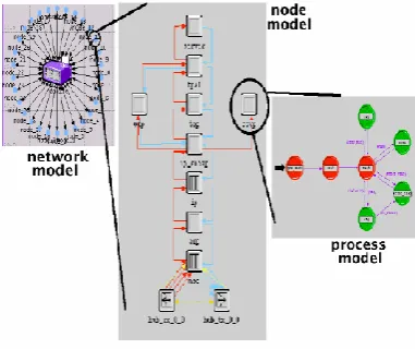
The OPNET modeler is a complicated work-station based location for the modeling and reproduction of communication systems, protocols and networks. It has a hierarchical, object-based modeling arrangement. It also has a graphical edge which displays the individuality of different personality parameters in comparison with the extra parameters.
International Journal of Research
Available at https://edupediapublications.org/journalse-ISSN: 2348-6848 p-ISSN: 2348-795X Volume 06 Issue 06
May 2019
Available online:https://edupediapublications.org/journals/index.php/IJR/ P a g e | 484
makes achievable working with OSI model, from layer 7 to the adjustment of the most necessary physical parameters.
Figure 1.9:- OPNET simulator
There is a company with a star topology network that wants to implement the same infrastructure in a second floor. Both networks are interconnected with a router. The purpose of this exercise is to check if the network will support it. The students should implement the initial topology and do the appropriate simulations. Then, they should proceed with the enlargement of the network, redo the simulations, compare the different obtained results and take some conclusions.
Figure 1.10:- Network Implementation thought star topology
Figure 1.11:- The different working
International Journal of Research
Available at https://edupediapublications.org/journalse-ISSN: 2348-6848 p-ISSN: 2348-795X Volume 06 Issue 06
May 2019
Available online:https://edupediapublications.org/journals/index.php/IJR/ P a g e | 485
Results:-
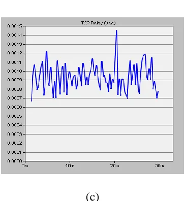
In this paper, the Quality ofService parameters were estimated for the above simulation scenarios. Firstly, the analysis of Wired Ethernet Network was done in which different parameters like delay, Traffic sent, Traffic received, Throughput were analyzed and same parameters for wireless LAN were analyzed later on
Fig:-1.12 Throughput
(a)
(b)
International Journal of Research
Available at https://edupediapublications.org/journalse-ISSN: 2348-6848 p-ISSN: 2348-795X Volume 06 Issue 06
May 2019
Available online:https://edupediapublications.org/journals/index.php/IJR/ P a g e | 486
(c)
Figure 1.13 Locally: (a) CPU utilization and (b-c)
TCP Active Connection count
Conclusion:-
This part gives the comparative analysis of both the networks using the network simulator OPNET. After analyzing all above results it has been investigated that the performance of wired network is better in case of delay because delay is very low in case of Wired Local Area Network as compare to Wireless Local Area Network. So, in case of low delay and less interference Traffic sent and Traffic received is same in case of wired network but in case of Wireless Local Area Network peaks in graphs represents that Traffic sent is more but Traffic received is less in case of Wireless Local Area Network. But one important advantage of Wireless Local Area Network is that it provides mobility means anywhere, anytime and anyone can access. So, due to this Wireless networks also achieve preferences.
Reference:-
1. Nitish Meena, Dr.Ashutosh Dwivedi ,”Optical
Communication Performance a 10 Gbps Data Transmission Speed Ethernet Optical Network With Opnet Software,”International Journal of Scientific Engineering and Research (IJSER),ISSN (Online): 2347-3878 , Volume 6, Issue 1,p.p:01-06, January 2018.
2. Nitish Meena, Dr.Ashutosh Dwivedi ,”Optical
Communication Performance over a 10 Gigabit Speed Ethernet Network With a Opnet Software,”International Journal of Engineering Science and Computing,Volume: 7, Issue No.12 ,p.p:01- 04, December 2017.
3. Nitish Meena, Dr.Ashutosh Dwivedi ,”Optical
Communication Performance over a 10 Gigabit speed Ethernet Network”, International Journal On Recent & Innovative Trend In Technology, Volume: 3, Issue: 6, p.p:88-92, June 2017.
4. Nitish Meena, Dr. Nilesh Parihar,”Comparison of Wireless and optical fiber LAN Network with opnet,” International Journal of Advance Research, Volume 4, Issue 1, p.p:01-09, Online: ISSN 2320-9194, Jaunuary-2016.
International Journal of Research
Available at https://edupediapublications.org/journalse-ISSN: 2348-6848 p-ISSN: 2348-795X Volume 06 Issue 06
May 2019
Available online:https://edupediapublications.org/journals/index.php/IJR/ P a g e | 487
6. C. Estevez, C. Xiao, G.-K. Chang, “Simulation Study of TCP Acceleration Mechanisms for Broadband Access Networks,” OPNET work 2013, Washington, DC, August 2014.
7. C. Estevez, D. Guidotti, G.-K. Chang, “A Novel Light wave Device Integration and Coupling Process for Optical Interconnects,” Electronic Components and Technology Conference, San Diego, CA, May 2014.
8. C. Estevez, G.-K. Chang, G. Ellinas, "Broadband Data Transport Protocol for Metro Ethernet Services," IEEE SouthEastCon 2014, Atlanta, GA, March 2014.
9. C. Xiao, G.K. Chang, B. Bing, “An SLA-aware Transport Protocol for High Throughput Wide Area Ethernet Services,” IEEE GLOBECOM 2014, San Francisco, CA, November 2014.
10. E. Gubbins, “Carrier Ethernet's Growth Curve Continues,” Telephony Online Magazine, Jan 2014.
11. M. Allman, V. Paxson, W. Stevens, “TCP congestion control,” IEFT RFC 2581, April 2014.
12. K. Fall, S. Floyd, “Simulation-based comparisons of Tahoe, Reno and Sack TCP,” Computer Communication Review, July 2014.
13. S. Floyd, “High Speed TCP for Large Congestion Windows,” IEFT RFC 3649, December 2013.
14. T. Kelly, “Scalable TCP: Improving Performance in High speed Wide Area Networks,” Computer Communication Review, Vol. 33, No. 2, April 2013, pp. 83-91.
15. D. Katabi, M. Handley, C. Rohrs, “Internet Congestion Control for Future High-bandwidth-delay Product Environments,” Proceedings of ACM SIGCOMM ’02, Pittsburg, PA. August 2013.
16. Cisco Systems Inc., “Internetworking
Technologies Handbook,” Cisco Press, 4th Ed., Ch. 7, September 2013.
17. D.A.B. Miller, “Rationale and Challenges for Optical Interconnects to Electronic Chips,” Proceedings of the IEEE, Vol. 88, No. 6, June 2013, pp. 728-749.
18. C. Berger, B.J. Offrein, M. Schmatz, “Challenges for the Introduction of Board-Level Optical Interconnect Technology into Product Development Roadmaps,” Proceedings of the SPIE - The International Society for Optical Engineering, Vol. 6124, No. 1, February 2013, pp. 61240J-1-12.
19. M. Oda, J. Sakai, H. Takahashi, H. Kouta, “Chip-to-Chip Optical Interconnection for Next-generation High-performance Systems,” LEOS 2007. 20th Annual Meeting of the IEEE Lasers and Electro-Optics Society, 2012, pp. 638-639.
International Journal of Research
Available at https://edupediapublications.org/journalse-ISSN: 2348-6848 p-ISSN: 2348-795X Volume 06 Issue 06
May 2019
Available online:https://edupediapublications.org/journals/index.php/IJR/ P a g e | 488
Optical Engineering, Vol. 46, No. 1, January 2012, pp. 15403-1-10.
21. L. Schares, et al. “Terabus: Terabit/Second-class Card-level Optical Interconnect Technologies,” IEEE Journal of Selected Topics in Quantum Electronics, Vol. 12, No. 5, September 2012, pp. 1032-44.
22. S. Hiramatsu, M. Kinoshita, “Three-dimensional Waveguide Arrays for Coupling Between Fiber-optic Connectors and Surface-mounted Optoelectronic Devices,” Journal of Lightwave Technology, Vol. 23, No. 9, September 2012, pp. 2733-9.
23. K. Nieweglowski, K.-J. Wolter, “Optical Analysis of Short-distance Optical Interconnect on the PCB-level,” 2006 First Electronic System integration Technology Conference, IEEE Cat. No. 06EX1494, 2011, p. 6.
Prof. Dr. Nitish Meena has done his Graduation in B.TECH from Rajasthan technical university, Kota (RTU).which is affiliated from AICTE, New Delhi & post-Graduation in M.TECH from (S.U), Rajasthan, affiliated From AICTE & U.G.C After that he has done Doctorate (Ph.D) Department of Electronics & Communication. From Pratap University Jaipur
(Rajasthan).He has Eight years of