Single-Layer Dual-Band Dual-Linear-Polarization Reflectarray
Antenna with Different Beams for Each Band
Chunhui Han*, Yunhua Zhang, and Qingshan Yang
Abstract—A novel single-layer unit cell structure is proposed to design a dual-band dual-linear-polarization reflectarray antenna with different beams for X and Ku bands. The unit cell structure is composed of a circular ring and two cross bow-tie structures combined by a circular patch. Five tunable geometric parameters can be optimized to achieve the required phase distributions of the reflectarray antenna with independent radiation patterns for each band which is a challenge for single-layer linearly polarized reflectarrays. Besides, the proposed unit cell structure has the ability to meet the demand of dual-polarization applications. A 301-element center-fed reflectarray with an octagon-shape aperture operating at X and Ku bands is designed, manufactured and measured to verify the dual-band performance of the proposed unit cell. The measured results show that the object of achieving different beams at different frequencies is realized with good radiation patterns at both designed frequencies. Besides, the similar radiation patterns for both linear polarizations are also achieved at both bands.
1. INTRODUCTION
Recently, microstrip reflectarray technology has attracted wide attention in many communication and radar applications due to its various advantages [1]. Its low cost, light weight and planar structure make it an alternative high gain antenna to traditional parabolic reflector antenna and phased array antenna. In its basic form, a microstrip reflectarray antenna is composed of an array of radiating elements printed on a flat surface, which are illuminated by a feed. The main principle for designing a reflectarray antenna is to control the phase of the wave reradiated from the radiating elements to form a planar phase front in the desired direction. Several methods have been used as the phase shift mechanism to obtain the desired reflecting phase, such as using element with variable size [2], phase delay line [3], and element rotation [4].
However, there are some drawbacks associated with reflectarray antennas, among which, narrow bandwidth is the most outstanding one [5]. Despite the narrow bandwidth performance, reflectarray antennas are well suited for dual-band demands in some special cases. In recent decades, several techniques have been proposed to achieve dual-band performance for reflectarray antennas, such as single-layer multi-resonance structures [6], multilayer structures [7–10] and frequency selective surface (FSS)-backed structures [11–13].
Furthermore, dual-band reflectarray antennas, which can maintain two different and independent radiation patterns for each operating band, are needed in some applications. In [14], Shaker and Cuhaci proposed an antenna system that is composed of a Ka-band FSS-backed reflectarray and a Ku-band conventional reflector. The FSS-backed reflectarray is designed in such a way that it is transparent in the operating band of the conventional reflector placed under the reflectarray slab. As a result, the hybrid antenna system has easily achieved two different and independent radiation patterns for each operating band. Besides, a new antenna system was reported in [13] for simplicity, in which the
Received 31 January 2017, Accepted 28 March 2017, Scheduled 10 April 2017
* Corresponding author: Chunhui Han ([email protected]).
combined by a circular patch, is proposed to design a single-layer dual-band dual-linear-polarization reflectarray antenna which can maintain two independent radiation patterns in X and Ku bands, respectively. There are five geometrical parameters which can be tuned to compensate the phase shifts at the designed frequencies so as to achieve different radiation patterns simultaneously, which is different from the techniques mentioned in [8] and [15]. Compared with our previous work [16], a wider reflecting phase range for both frequencies is achieved and simultaneously satisfied the designed phase distribution at two designed center frequencies, which can efficiently reduce the phase errors. Besides, the proposed unit structure can satisfy the demand of dual-polarization applications. Finally, a 301-element center-fed reflectarray forming an octagon-shape aperture operating at X and Ku band is designed, manufactured and measured for verification. The measured results have shown better radiation performances at the two designed frequencies.
The paper is organized as follows. Section 2 introduces the novel dual-band single-layer unit structure. In Section 3, we present the design approach as well the measured results. Finally, section 4 presents the conclusion of this study.
2. UNIT CELL DESIGN
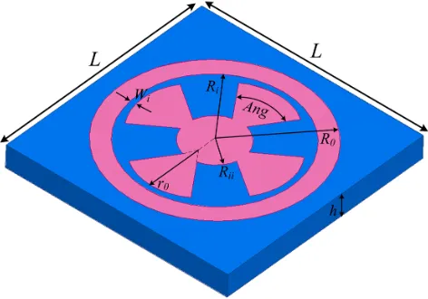
Figure 1 depicts the proposed single-layer unit-cell structure working at X and Ku bands for dual linear polarizations. As one can see, the proposed unit cell consists of a circular ring and two cross bow-tie structures, which are orthogonally placed and combined by a circular patch. The unit cell is etched on a 0.81-mm-thickness Rogers 4003 grounded substrate with relative permittivity (εr) of 3.38 and loss tangent of 0.0027. The spacing of the unit cell is set to be L = 8 mm, which is equivalent to 0.27 wavelength at 9 GHz and 0.35 wavelength at 13 GHz. The outer radius of the circular ring Ro is optimized for wide linear phase range at both 9 GHz and 13 GHz, and an optimum value ofRo= 3.4 mm is obtained for all unit cells, which also determines the minimum limit of both frequency bands. Thus, abrupt geometry variations for adjacent unit cells in the traditional reflectarrays can be avoided [17] which is good for achieving almost equal mutual coupling between adjacent unit cells, especially for compact reflectarrays.
As shown in Figure 1, there are five tunable geometrical parameters to control the reflecting phases at 9 GHz and 13 GHz:
(1) The inner radius of the circular ring Ri, which is the main parameter used to control the
reflecting phase for both bands and make sure that 9 GHz and 13 GHz fall in the range of lower and upper bands respectively.
(2) The gap between the circular ring and the cross bow-tie structureWi, which affects the mutual coupling between the circular ring and the cross bow-tie structure.
(3) The angle of the cross bow-tie structureAng, which mainly control the reflecting phase for the upper band.
(4) The radius for the fan section of the cross bow-tie structurer0, which is represented by parameter
M, Ri and Wi via r0 = (1−M/2)×(Ri −Wi). M should be limited in the range of 0 < M <1 to
Figure 1. Unit cell structure of the reflectarray antenna.
(5) The radius of the inner circular ring Rii, which connects the cross bow-tie structure and is represented by parameter M,N,Ri andWi via Rii= (N/2 +M/2)×(Ri−Wi). N should be limited in the range of 0< N <1 for the same reason above.
To investigate the phase responses of the unit cell with different configurations, an infinite array model is built in HFSS using master-slave boundary condition and Floquet port excitation. Then, the parameter sweeping is carried out by tuning the values of Ri, Wi, Ang, M, andN for the unit cell as given in Table 1.
Table 1. Geometrical parameters and their sweeping ranges.
Parameters Ri (mm) Wi (mm) Ang (deg) M N
Ranges 1.6 : 0.1 : 3.2 0.1 : 0.1 : 0.5 30 : 1 : 75 0.1 : 0.1 : 0.6 0.1 : 0.1 : 0.6
Figure 2 shows the influence of these five parameters on the phase response curves at both two bands, from which we can see that the phase response mainly varies with the value of Ri for both 9 GHz and 13 GHz. Parameters Wi, Ang, M and N also have effect on the phase responses at both two frequencies, which means more possible reflecting phases can be realized to simultaneously satisfy the desired reflecting phases for the designed radiation patterns at two bands. Besides, the reflecting phases can be tuned in a wider range for 13 GHz than that for 9 GHz by varying the value of Wi,Ang, M and N. We thus obtain the reflecting phases of the unit cell for all the configurations (Ri,Wi,Ang, M and N). Figure 3 shows the achievable reflecting phases of the proposed unit cell at both bands, and each point (p1, p2) in the blue area indicates one of the achievable unit-cell configurations (Ri, Wi,Ang, M and N), wherep1 and p2 are the corresponding achievable reflecting phases ranging from
−180◦ to +180◦ at 9 GHz and 13 GHz, respectively. The blue area occupies more than 80% of the entire region, i.e., −180◦ ∼+180◦ for both frequencies, which means most of reflecting phases required for the designed reflectarray can be fulfilled by properly adjusting the configuration parameters ofRi,Wi,Ang,
M and N for each unit cell of the reflectarray. Compared with our previous work [16], the achievable reflecting phase range is significantly broadened, which helps to achieve better radiation performances when designing a dual-band reflectarray antenna with two mutually independent radiation patterns at each operating band.
(c) (d)
Figure 2. Reflecting phases of the unit cell at 9 GHz and 13 GHz, respect toRi (a) for different values of Wi (Ang = 60 deg, M = 0.5, N = 0.3), (b) for different values of Ang (Wi = 0.1 mm, M = 0.5,
N = 0.3), (c) for different values ofM (Wi = 0.1 mm, Ang= 60 deg, N = 0.3), (d) for different values of N (Wi= 0.1 mm, Ang= 60 deg,M = 0.5).
Figure 3. Achievable phase distribution of 9 GHz versus that of 13 GHz.
3. REFLECTARRAY DESIGN AND RESULTS
3.1. Design Principle
Generally, the reflecting phases of linearly polarized single-layer dual-resonance structure are hard to tune independently at two different frequencies due to the mutual coupling inside the unit cell. As a result, it is hard to maintain mutually independent radiation patterns at each operating band. Here, we present an approach to solve the problem for our proposed unit cell.
At the first step, the required phase distributions for each unit cell on the reflectarray plane at 9 GHz and 13 GHz are calculated, respectively, according to Eq. (1)
φR=k0×(di−(xicosϕ0+yisinϕ0) sinθ0) (1)
where k0 is the propagation constant in free space, di the distance from the phase center of the feed
to the position of the ith unit cell on the reflectarray plane (xi, yi), and (θ0, ϕ0) the designed main
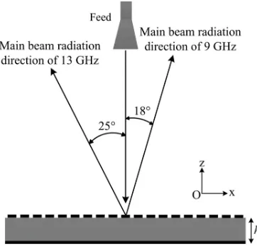
beam radiation direction of the reflectarray antenna. Here, a 301-element center-fed reflectarray with an octagon-shape aperture with diameter of 152 mm operating at X and Ku bands is designed, and the main beam radiation directions are designed to be (θ0, ϕ0) = (18◦,0◦) for 9 GHz and (θ0, ϕ0) = (25◦,180◦)
for 13 GHz, respectively, with the same feed position for both frequencies. In this design, a feed of pyramid horn is chosen and positioned, which is linearly polarized. The designed feed horn can operate at both X and Ku bands and it is positioned 123 mm right above the center of the reflectarray plane with focus-to-diameter (F/D) ratio of 0.8 providing proper illumination with −10 dB tapering on the edge of the reflectarray plane. The schematic diagram of the designed dual-band reflectarray antenna is shown in Figure 5.
Figure 5. Schematic diagram of the designed reflectarray antenna.
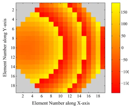
Figure 6. Required reflecting phases for both 9 GHz and 13 GHz.
The required reflecting phases of all the unit cells at both 9 GHz and 13 GHz are shown in Figure 6, and the red star points (p1, p2) represent all the required unit cells on the reflectarray plane, where
p1 and p2 are the corresponding required reflecting phases ranging from −180◦ to +180◦ at 9 GHz
and 13 GHz, respectively. There are only 160 red star points shown in Figure 6, in consideration of the symmetry about the x-axis. Figure 7 and Figure 8 plot the required phase distributions of the reflectarray aperture at 9 GHz and 13 GHz, respectively.
Figure 7. Required phase distribution of the designed reflectarray aperture at 9 GHz.
Figure 8. Required phase distribution of the designed reflectarray aperture at 13 GHz.
upper and lower frequencies concurrently [18]. Due to the inevitable phase errors, the candidates that produce the best phase shifts at both frequencies are selected by minimizing the following error function:
e(m, n) =
i=l,u
Φdesired(fi)(m, n)−Φachieved(fi)(m, n) (2)
where (m, n) represents the number of the unit cell in two-dimension of the reflectarray surface; Φachieved (fu) and Φachieved (fl) are the achievable phase shifts of the upper and lower frequencies; Φdesired (fu) and Φdesired (fl) are the calculated phase shifts of the upper and lower frequencies. In practice, the error function introduced in Eq. (2) is tested for all unit cell configurations as shown in Figure 3 and the unit cell configurations with lowest errors are chosen as the optimum elements. A simple MATLAB code is developed to find the optimum elements for all the unit cells on the reflectarray plane.
3.2. Results
Finally, the center-fed dual-band reflectarray antenna working at X and Ku bands is successfully designed and fabricated, which aims to achieve mutually independent radiation patterns for each band. The fabricated reflectarray is octagon-shaped with diameter of 152 mm and 301 elements, as shown in Figure 9, where the fiberglass is utilized to support the feed horn and the relfectarray plane in order to decrease blocking effect in the measurement system.
Figure 9. Prototype of the fabricated reflectarray.
Figure 10. Measured co-polarE-plane radiation patterns for X and Y polarizations at 9 GHz.
Figure 11. Measured co-polar E-plane radiation patterns for X and Y polarizations at 13 GHz.
the dual-band performances of the proposed unit cell. The measured results show that our target for realizing different beams at different frequencies is achieved. The measured main beam directions are around (18◦, 0◦) for 9 GHz and (25◦, 180◦) for 13 GHz, respectively, with a deviation less than 0.5◦ as expected. Besides, good radiation performances at both designed frequencies are also obtained with similar radiation patterns for both linear polarizations achieved at both bands.
REFERENCES
1. Huang, J. and J. A. Encinar,Reflectarray Antennas, John Wiley & Sons Inc., Hobo Ken, NJ, 2007. 2. Encinar, J. A., “Design of two-layer printed reflectarrays using patches of variable size,” IEEE
Transactions on Antennas and Propagation, Vol. 49, No. 10, 1403–1410, Oct. 2001.
3. Chang, D. C. and M. C. Huang, “Microstrip reflecarray antenna with offset feed,” Electronics Letters, Vol. 28, No. 16, 1489–1491, 1992.
4. Yu, A., F. Yang, A. Z. Elsherbeni, J. Huang, and Y. Kim, “An offset-fed X-band reflectarray antenna using a modified element rotation technique,” IEEE Transactions on Antennas and Propagation, Vol. 60, No. 3, 1621–1624, Mar. 2012.
5. Pozar, D. M., “Bandwidth of reflectarrays,” Electronics Letters, Vol. 39, No. 21, 1490–1491, Oct. 2003.
6. Chaharmir, M. R., J. Shaker, N. Gagnon, and D. Lee, “Design of broadband, single layer dual-band large reflectarray using multi open loop elements,” IEEE Transactions on Antennas and Propagation, Vol. 58, No. 9, 2875–2883, Sep. 2010.
7. Encinar, J. A., “Design of a dual frequency reflectarray using microstrip stacked patches of variable size,” Electronics Letters, Vol. 32, No. 12, 1049–1050, Jun. 1996.
8. Han, C., C. Rodenbeck, J. Huang, and K. Chang, “A C/Ka dual frequency dual Layer circularly polarized reflectarray antenna with microstrip ring elements,”IEEE Transactions on Antennas and Propagation, Vol. 52, No. 11, 2871–2876, Nov. 2004.
9. Chulmin, H., J. Huang, and C. Kai, “A high efficiency offset-fed X/kadual-band reflectarray using thin membranes,” IEEE Transactions on Antennas and Propagation, Vol. 53, No. 9, 2792–2798, Sep. 2005.
10. Shih-Hsun, H., et al., “An offset linear-array-fed Ku/Ka dual-band reflectarray for planet cloud/precipitation radar,”IEEE Transaction on Antennas and Propagation, Vol. 55, No. 11, 3114– 3122, Nov. 2007.
11. Li, J. F., Q. Chen, S. W. Qu, Q. Yuan, and K. Sawaya, “Dual-frequency reflectarray design using sandwiched FSS,”Proc. Asia-Pacific Microwave Conf. (APMC), 877–880, 2010.
13. Chaharmir, M. R., J. Shaker, and H. Legay, “Dual-band Ka/X reflectarray with broadband loop elements,” IET Microwave, Antennas and Propagation, Vol. 4, No. 2, 225–231, 2010.
14. Shaker, J. and M. Cuhaci, “Multi-band, multi-polarisation reflector-reflectarray antenna with simplified feed system and mutually independent radiation patterns,” IET Microwaves, Antennas and Propagation, IEE Proceedings, Vol. 152, No. 2, 97–101, 2005.
15. Deng, R. Y., Y. L. Mao, S. H. Xu, and F. Yang, “A single-layer dual-band circularly polarized reflectarray with high aperture efficiency,” IEEE Transactions on Antennas and Propagation, Vol. 63, 3317–3320, Jul. 2015.
16. Han, C. H. and Y. H. Zhang, “Single layer dual-band reflectarray antenna with two independent radiation patterns,”IET International Radar Conference, 1–4, Hangzhou, 2015,
17. Li, J. F., Q. Chen, Q. W. Yuan, and K. Sawaya, “Reflectarray element using interdigital gap loading structure,”Electronics Letters, Vol. 47, No. 2, 83–85, Jan. 2011.