Miniaturized Single-Feed Cross-Aperture Coupled Circularly
Polarized Microstrip Patch Antenna
Jianxing Li1, 2, *, Jianying Guo1, Anxue Zhang1, 3, William T. Joines2, and Qing Huo Liu2
Abstract—A novel miniaturized single-feed cross-aperture coupled circularly polarized (CP) microstrip patch antenna loaded by four identical shorting strips is proposed and discussed. Each shorting strip underneath the edges of the radiating patch is connected to the ground plane via an array of three identical and equidistant shorting pins. With the assistance of the capacitance offered by the radiating patch and the shorting strips, and the inductance induced by the shorting pins, the patch size and overall size of the proposed antenna have been significantly reduced by 75% and 69%, respectively, compared with the conventional antenna. An antenna prototype with an overall size of 50 mm×50 mm×7.548 mm (0.317λ0×0.317λ0 ×0.048λ0) and a patch size of 29.43 mm×27.85 mm (0.186λ0 ×0.176λ0) has been fabricated and measured, which shows a measured 10-dB return loss bandwidth of 92 MHz (4.76%) from 1.886 to 1.978 GHz with a maximum right-handed CP (RHCP) gain of 4.9 dBic. The measured 3-dB axial ratio (AR) bandwidth is 28 MHz (1.46%) from 1.899 to 1.927 GHz with a 3-dB AR beamwidth of more than 140◦ across the operating bandwidth.
1. INTRODUCTION
Circularly polarized (CP) microstrip patch antennas have been extensively used for many applications such as global navigation satellite systems (GNSS), wireless local area network (WLAN), medical implant communication service (MICS), and radio frequency identification (RFID). The popularity of circular polarization is because it is not only able to reduce the effects of multipath reflection and Farady rotation, but also release the orientation constraints on the transmitting and receiving antennas. Meanwhile, microstrip patch antennas feature light weight, low profile, low cost, ease of fabrication, and integration with other circuitries. Apart from adequate bandwidth and medium gain, the CP microstrip patch antennas are always demanded with compact sizes for many modern wireless terminals, for instance, portable GNSS receivers and handheld RFID readers. Thus, many promising CP microstrip patch antennas have been proposed [1–8]. Compared with the dual-feed CP microstrip patch antennas [1–5], the single-feed ones [6–8] exhibit more compactness, since the dual-feed designs always need auxiliary feeding networks that render larger sizes.
To date, various single-feed CP microstrip patch antennas with miniaturized sizes have been reported [9–15]. Although asymmetric slits and cross-shaped slots can be introduced to realize miniaturization [9, 10], the measured 3-dB axial ratio (AR) bandwidths are usually narrow, which are 0.5% and 0.7%, respectively. A compact UHF RFID patch antenna was proposed based on an artificial magneto-dielectric material [11]. The antenna has an overall size of 0.303λ0×0.303λ0×0.01λ0 with a measured peak gain of −3.75 dBic over the frequency band. A reactive impedance surface and complementary split-ring resonators were loaded to miniaturize the CP patch antenna size
Received 13 March 2016, Accepted 20 April 2016, Scheduled 4 May 2016 * Corresponding author: Jianxing Li (jianxingli.china@gmail.com).
1 School of Electronic and Information Engineering, Xi’an Jiaotong University, Xi’an, Shaanxi 710049, China. 2 Department of
(0.327λ0 ×0.327λ0 ×0.028λ0), which has a measured gain of 3.7 dBic and 3-dB AR bandwidth of 1.1% [12]. In [13], meta-surfaces and space-filling meta-resonators were combined to reduce the CP patch antenna size (0.435λ0 ×0.435λ0 ×0.019λ0) [13]. The antenna has a 3-dB AR bandwidth of 1.05%. Nasimuddin et al. proposed a miniaturized GNSS antenna using square-ring slots and grounded patches [14]. The overall size of the antenna is 0.316λ0 ×0.316λ0 ×0.026λ0 with a maximum gain of 4.65 dBic and 3-dB AR bandwidth of 2.2%. A microstrip patch antenna was miniaturized using grounded strips and shorting pins (0.349λ0×0.349λ0 ×0.038λ0) [15]. However, the antenna is linearly polarized with a relatively narrow impedance bandwidth of 1.6%.
In this paper, a novel miniaturized single-feed cross-aperture coupled CP microstrip patch antenna is proposed. Four identical shorting strips are symmetrically loaded underneath the radiating patch of the proposed antenna. Then, an array of three identical and equidistant shorting pins is introduced to connect each shorting strip to the ground plane. The proposed antenna has achieved a significant size reduction, as a result of the capacitive loading by the shorting strips and the radiating patch, and the inductive loading by the shorting pins. The operating mechanisms for the CP generation and antenna miniaturization were studied and revealed by full-wave simulations performed with the aid of Ansoft HFSS 12.0 [16]. Parametric studies have been conducted to analyze the effect of the geometrical parameters on the performance of the proposed antenna. The design concept is verified by measurement, showing that the antenna has reasonable bandwidth, moderate gain, wide AR beamwidth, and high radiation efficiency.
2. ANTENNA DESIGN 2.1. Antenna Configuration
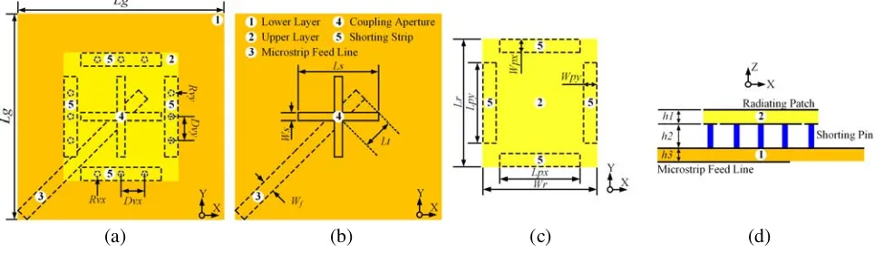
The configuration of the proposed single-feed cross-aperture coupled CP microstrip patch antenna is presented in Figure 1. The antenna comprises two layers of printed circuit boards (PCB) (RO4003C, relative permittivity εr = 3.38, loss tangent tanδ = 0.0027, and thickness h1 and h3, respectively). The thickness of the air gap between the upper and lower substrates is denoted as h2. The radiating patch with lengthLr and width Wr is printed onto the top side of the upper substrate. A cross-shaped aperture with length Ls and width Ws is etched in the ground plane printed onto the top side of the lower substrate, to realize the coupling between the microstrip feed line and the radiating patch. The microstrip feed line with a tuning stub and with width Wf, positioned along the 45◦ diagonal line direction in the x-y plane, is printed onto the bottom side of the lower substrate. The length of the ground plane and the tuning stub is denoted byLg and Lt, respectively.
Four shorting strips printed onto the bottom side of the upper substrate are symmetrically loaded underneath the edges of the radiating patch. As depicted in Figure 1, the outside edges of the shorting strips are aligned with those of the radiating patch. The shorting strips along the x and y directions are with length and width of (Lpx,Wpx) and (Lpy,Wpy), respectively. Each shorting strip is connected
(c) (d)
(a) (b)
to the ground plane through an array of shorting pins, which consists of three identical and equidistant shorting pins. The radius and adjacent separation of the shorting pins along the x and y directions are (Rvx, Dvx) and (Rvy, Dvy), respectively. To simplify the design process, the length and width of the x-directed shorting strips are set to be the same as those of the y-directed ones (Lp =Lpx =Lpy,
Wp = Wpx = Wpy), and the radius and adjacent separation of the x-directed shorting pins are also selected to be the same as those of they-directed ones (Rv =Rvx=Rvy,Dv =Dvx=Dvy).
2.2. Comparison with a Conventional CP Microstrip Antenna
The geometrical parameters of the proposed cross-aperture coupled CP patch antenna were optimized and determined after several design iterations, as tabulated in Table 1. Also shown are the geometrical parameters of a conventional cross-aperture coupled CP patch antenna without the shorting strips and shorting pins. Both antennas are with the sense of right-handed CP (RHCP) and minimum AR at the same operating frequency of 1.9 GHz. The proposed antenna has an overall size of 50 mm×50 mm× 7.548 mm (0.317λ0×0.317λ0×0.048λ0) and a patch size of 29.43 mm×27.85 mm (0.186λ0×0.176λ0), whereas those for the reference antenna are 90 mm×90 mm×7.548 mm (0.57λ0×0.57λ0×0.048λ0) and 60.5 mm×55.5 mm (0.383λ0×0.352λ0), implying that a significant reduction of 69% in the overall size and 75% in the patch size has been achieved, whereλ0 is the free-space wavelength at 1.9 GHz.
Table 1. Optimized geometrical parameters for the reference and the proposed antennas (unit: mm).
Parameter Reference Proposed Parameter Reference Proposed
h1 1.524 1.524 Lp – – 20.42
h2 4.5 4.5 Ws 1.5 1.5
h3 1.524 1.524 Wf 4.8 4.8
Lg 90.0 50.0 Wr 55.5 27.85
Ls 29.0 17.9 Wp – – 3.12
Lt 10.2 11.2 Rv – – 0.6
Lr 60.5 29.43 Dv – – 4.27
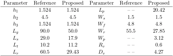
Figure 2 compares the performances of the proposed antenna and the reference antenna in terms of return loss, and broadside AR and RHCP gain. As summarized in Table 2, the reference antenna exhibits wider bandwidths with a 10-dB return loss bandwidth of 12.3% (1835–2075 MHz) and a 3-dB AR bandwidth of 2.1% (1882–1922 MHz), however, the proposed antenna shows narrower bandwidths with a 10-dB return loss bandwidth of 4.24% (1869–1950 MHz) and a 3-dB AR bandwidth of 1.05% (1889–1909 MHz). Moreover, the simulated broadside RHCP gain of the proposed antenna (4.8 dBic) at 1.9 GHz is smaller than that of the reference antenna (8.1 dBic). This is reasonable since the proposed antenna is electrically much smaller compared with the reference antenna [17]. Further improvement on the return loss as well as the AR bandwidth for the proposed antenna can be achieved by using the series and parallel feed configurations [1], which is out of the scope of this paper. The simulated AR as a function of the angle in the upper hemisphere for the proposed and the reference antennas are shown in Figure 3. It manifests that the 3-dB AR pattern coverage of the proposed antenna is much broader than that of the reference one. Specifically, the AR beamwidth of the proposed antenna in the x-z and
y-z planes is 140◦ and 142◦, respectively; whereas those for the reference antenna are 110◦ and 114◦, respectively.
Table 2. Performance comparison of the reference and the proposed antennas.
@ @@
Impedance bandwidth (10-dB return loss)
CP bandwidth (3-dB axial ratio)
(a) (b)
Figure 2. Comparison of the simulated results for the reference and proposed antennas. (a) Return loss. (b) Broadside AR and RHCP gain.
(a) (b)
Figure 3. Spatial AR in the upper hemisphere. (a) Proposed antenna. (b) Reference antenna.
2.3. Mechanisms for the CP Radiation and Miniaturization
(d)
(a) (b) (c)
Figure 4. Surface current distributions of the proposed antenna. (a) t= 0. (b) t=T/8. (c) t=T/4. (d)t= 3T/8.
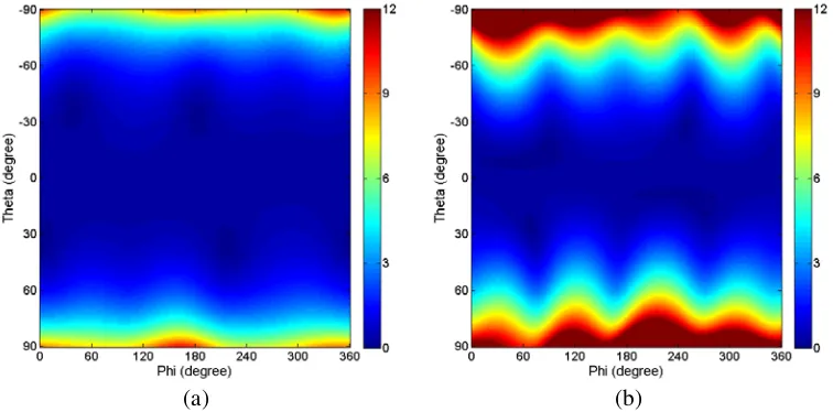
As mentioned above, when compared with the reference antenna, a significant size reduction has been achieved for the proposed antenna. It attributes to the capacitive loading from the radiating patch and the shorting strips, and the inductive loading from the shorting pins. To understand the operating mechanism underlying the miniaturization more intuitively, the current density distributions on the radiating patch as well as the loading structure are illustrated in Figure 5. We can see that the surface current distribution on the radiating patch of the proposed antenna is similar to that of the conventional CP patch antenna, whereas strong vertical currents distributed along the shorting pins also can be observed from Figure 5(b), which increase the resonant lengths for the TMz01 and TMz10 modes considerably, and hence results in a significant size reduction.
(b) (a)
Figure 5. Surface current distribution of the proposed antenna. (a) Top view. (b) Side view.
3. PARAMETRIC STUDIES
Parametric studies were conducted by full-wave simulations to investigate the effects of the geometrical parameters on the return loss and AR performance of the proposed antenna, and to provide more information on the design and optimization of the proposed antenna. Note that only one geometrical parameter is varied each time while the others are kept unchanged.
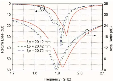
The return loss and broadside AR with changing the length of the shorting strips (Lp) from 20.12 to 20.72 mm is shown in Figure 6. The operating frequency decreases with increasingLp. The reason is that increasing Lp enlarges the overlapping areas between the shorting strips and the radiating patch, leading to greater capacitance. As Lp increases, the minimum achievable AR becomes larger. The optimal AR at 1.9 GHz is obtained for a length of 20.42 mm.
Figure 6. Return loss and AR with varying the length of the shorting strips,Lp.
Figure 7. Return loss and AR with varying the width of the shorting strips,Wp.
Figure 8. Return loss and AR with varying the separation of the shorting pins,Dv.
Figure 9. Return loss and AR with varying the radius of the shorting pins,Rv.
frequency shifts downwards. The optimal AR at 1.9 GHz occurs for a width of 3.12 mm and the AR is degraded when Wp deviates from 3.12 mm.
The frequency response of the return loss and broadside AR when the adjacent separation between the shorting pins (Dv) varies from 3.97 to 4.57 mm is shown in Figure 8. The operating frequency shifts upwards and AR is degraded asDv increases. The reason for this phenomenon is that the current distributed along the vertical shorting pins decreases as the separation is enlarged, which induce smaller phase delays for a given loaded inductance. The minimum AR at 1.9 GHz is achieved when the separation is 4.27 mm.
Figure 9 presents the effect of the radius (Rv) of the shorting pins on the performance of the return loss and broadside AR. The shorting pins can be treated similarly as the metal vias [18]. Increasing
Rv results in smaller inductance. Thus, the operating frequency is shifted downwards. The AR is deteriorated when Rv increases and the minimum AR for 1.9 GHz appears with a radius of 0.6 mm.
4. EXPERIMENTAL RESULTS AND DISCUSSIONS
Very good agreement can be observed. The measured 10-dB return loss bandwidth is 92 MHz (4.76%) from 1.886 to 1.978 GHz. The measured and simulated broadside AR and RHCP gain are shown in Figure 11(b). The measured 3-dB AR bandwidth is 28 MHz (1.46%) from 1.899 to 1.927 GHz with minimum measured AR occurs at 1.913 GHz. Further examinations show that the measured operating frequency shifts upwards slightly when compared with the simulated results. It is most likely owing to the fact that the prototype was assembled manually; therefore the thickness of the air gap between the upper and lower substrates may deviate slightly from the designed value. Besides, the nylon rods and nuts shown in Figure 10 to support the prototype were not taken into account in the simulations. Furthermore, the relative permittivity of the substrates may not be totally uniform. As shown in Figure 11(b), the measured RHCP gain maintains above 4.5 dBic across the 3-dB AR bandwidth, and the maximum RHCP gain of 4.9 dBic is obtained at 1.913 GHz. The simulated radiation efficiency of the proposed antenna is larger than 93% over the 3-dB AR bandwidth.
(b)
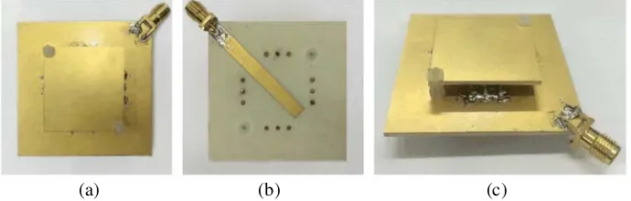
(a) (c)
Figure 10. The fabricated antenna prototype. (a) Top view. (b) Bottom view. (c) Overview.
Table 3. Comparison of the proposed antenna and other recent reported antennas.
Reference Size (λ0×λ0)
10-dB RLBW (%)
3-dB ARBW (%)
Gain (dBic)
[9] 0.288×0.288 2.53 0.50 4.30
[10] 0.274×0.274 1.97 0.66 3.80
[11] 0.304×0.304 0.60 Not given −3.75
[12] 0.327×0.327 4.90 1.68 Not given
[13] 0.435×0.435 Not given 1.05 4.15
This work 0.317×0.317 4.76 1.46 4.90
The proposed miniaturized cross-aperture coupled CP microstrip antenna has been compared with some other recent reported antenna designs. Table 3 summarizes the detailed comparison regarding the antenna size and measured performance between the proposed antenna and other antennas, where λ0 denotes the free-space wavelength of the frequency with minimum AR, RLBW denotes the return loss bandwidth, and ARBW denotes the AR bandwidth. Although those antennas designed in [9–11] have slightly smaller overall sizes, their operating frequency bandwidths are much narrower than that of the proposed antenna. The proposed antenna has similar overall size and measured performance to those of the antenna presented in [12]. When compared with the proposed antenna, the antenna introduced in [13] occupies the largest space but with a narrower operating bandwidth. Therefore, the proposed antenna possesses moderate overall size, relatively wider operating bandwidth, and largest measured CP gain.
(b) (a)
Figure 11. Simulated and measured results. (a) Return loss. (b) Broadside AR and RHCP gain.
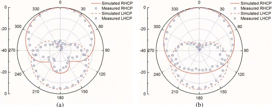
(b) (a)
Figure 12. Simulated and measured radiation patterns. (a) x-zplane. (b) y-z plane.
in both planes. It should be noted that the level of back radiation is somewhat high for the proposed antenna, owing to the longer apertures etched on the lower substrate, which has a relatively smaller dielectric constant, i.e., 3.38. To reduce the level of the back radiation, one can use a substrate with larger dielectric constant, e.g., Rogers 6006/6010 to implement the feed board.
5. CONCLUSION
REFERENCES
1. Targonski, S. D. and D. M. Pozar, “Design of wideband circularly polarized aperture-coupled microstrip antenna,”IEEE Trans. Antennas Propag., Vol. 41, No. 2, 214–219, 1993.
2. Pozar, D. M. and S. M. Duffly, “A dual-band circularly polarized aperture coupled stacked microstrip antenna for global positioning satellite,”IEEE Trans. Antennas Propag., Vol. 45, No. 11, 1618–1625, 1997.
3. Zhou, Y. J., C. C. Chen, and J. L. Volakis, “Dual band proximity-fed stacked patch antenna for tri-band GPS applications,” IEEE Trans. Antennas Propag., Vol. 55, No. 1, 220–223, 2007. 4. Chen, M. and C. C. Chen, “A compact dual-band GPS antenna design,”IEEE Antennas Wireless
Propag. Lett., Vol. 12, 245–248, 2013.
5. Li, J. X., H. Y. Shi, H. Li, and A. X. Zhang, “Quad-band probe-fed stacked annular patch antenna for GNSS applications,”IEEE Antennas Wireless Propag. Lett., Vol. 13, 372–375, 2014.
6. Vlasits, T., E. Korolkiewicz, A. Sambell, and B. Robinson, “Performance of a cross-aperture coupled single feed circularly polarised patch antenna,” Electron. Lett., Vol. 32, No. 7, 612–613, 1996. 7. Yang, K. P. and K. L. Wong, “Dual-band circularly-polarized square microstrip antenna,” IEEE
Trans. Antennas Propag., Vol. 49, No. 3, 377–382, 2001.
8. Falade, O. P., M. U. Rehman, Y. Gao, X. D. Chen, and C. G. Parini, “Single feed stacked patch circular polarization antenna for triple band GPS receivers,”IEEE Trans. Antennas Propag., Vol. 60, No. 10, 4479–4484, 2012.
9. Nasimuddin, X. M. Qing, and Z. N. Chen, “Compact asymmetric-slit microstrip antennas for circular polarization,”IEEE Trans. Antennas Propag., Vol. 59, No. 1, 285–288, 2011.
10. Nasimuddin, Z. N. Chen, and X. M. Qing, “A compact circularly polarized cross-shaped slotted microstrip antenna,”IEEE Trans. Antennas Propag., Vol. 60, No. 3, 1584–1588, 2012.
11. Chung, H., Y. Lee, and J. Choi, “Miniaturization of an UHF RFID reader antenna using an artificial magneto-dielectric,” Microw. Opt. Technol. Lett., Vol. 52, No. 9, 1926–1930, 2010.
12. Dong, Y., H. Toyao, and T. Itoh, “Design and characterization of miniaturized patch antennas loaded with complementary split-ring resonators,”IEEE Trans. Antennas Propag., Vol. 60, No. 2, 772–785, 2012.
13. Xu, H. X., G. M. Wang, J. G. Liang, M. Q. Qi, and X. Gao, “Compact circularly polarized antennas combining meta-surfaces and strong space-filling meta-resonators,”IEEE Trans. Antennas Propag., Vol. 61, No. 7, 3442–3450, 2013.
14. Nasimuddin, X. M. Qing, and Z. N. Chen, “A compact circularly polarized slotted patch antenna for GNSS applications,”IEEE Trans. Antennas Propag., Vol. 62, No. 12, 6506–6509, 2014.
15. Yang, M., Z. N. Chen, P. Y. Lau, X. M. Qing, and X. X. Yin, “Miniaturized patch antenna with grounded strips,”IEEE Trans. Antennas Propag., Vol. 63, No. 2, 843–848, 2015.
16. Ansoft High Frequency Structural Simulator (HFSS) version 12.0. Framingham, MA, USA, Ansoft Corp., 2006.
17. Sievenpiper, D. F., D. C. Dawson, M. M. Jacob, T. Kanar, S. Kim, J. Long, and R. G. Quarfoth, “Experimental validation of performance limits and design guidelines for small antennas,” IEEE Trans. Antennas Propag., Vol. 60, No. 1, 8–19, Jan. 2012.