Analysis of Simulation Parameters of Pulse Shaping
FIR Filter for WCDMA
Pannalal Prabhakar & Pavan Kumar
M.Tech Student (Communication System) MUIT, Lucknow India
[email protected]
Assistant professor, Maharishi University of Information Technology, Lucknow India
[email protected]
Abstract:
Digital Signal processing techniques are being used to improve the performance of 3G systems. W-CDMA (known as IMT-2000 direct spread spectrum) is a third-generation (3G) mobile wireless technology that promises much higher data speeds to mobile and portable wireless devices than commonly offered in
today's market. W-CDMA can support
mobile/portable voice, images, data, and video communications at up to 2 Mbps (local area access) or 384 Kbps (wide area access). It enables several users to transmit their information over the same channel bandwidth. In the mode of transmission a trade off exists between bandwidth containment in frequency domain and ripple attenuation in time domain. It is this trade off of bandwidth containment versus ripple amplitude is considered during system design when developing a data transmission system that employs pulseshaping.
This thesis involves the application of signal processing techniques to wireless communications in emerging area of WCDMA that can help to achieve improvement in results related to transmission performance. The objective of our work is related with industrial viewpoint application design that involves advanced signal processing technology that can increase the wireless system capacity and also improve the communication quality including the reduction of all types of interference. This work deals with simulation model of square root raised cosine pulse shaping filter for WCDMA with different parameters of the filter. Our work deals with study of Simulation Parameters (Number of Bits, Number of Errors) of Pulse Shaping FIR Filter at different group delay and roll off factor for WCDMA. We have tested WCDMA model at different SNR by using scatter plot eye diagram and spectrum scope to find out optimum value of delay and roll off factor of root raise cosine filter that can give minimum bit error.
1.
Introduction
Recently, extensive investigations have been carried out into the application of a code division multiple
access (CDMA) system as an air interface multiple access scheme for IMT-2000/UMTS (International Mobile Telecommunications System 2000/Universal Mobile Telecommunications System). It appears that CDMA is the strongest candidate for the third-generation wireless personal communication systems. Many research and development (R&D) projects in the field of wideband CDMA have been going on in Europe, Japan, the United States, and Korea [1- 5]. It seems that wideband CDMA will be an appropriate answer to the question: “What will be the multiple access scheme for IMT-2000/UMTS?” Emerging requirements for higher rate data services and better spectrum efficiency are the main drivers identified for the third-generation mobile radio systems. In the ITU, third generation networks are called IMT-2000, and in Europe, UMTS. Since 1985, the ITU has been developing IMT-2000, previously termed Future Public Land Mobile Telephone System (FPLMTS). In ETSI, UMTS standardization started 1990 when sub technical committee SMG5 was established. The main objectives for the IMT-2000 air interface can be summarized as:
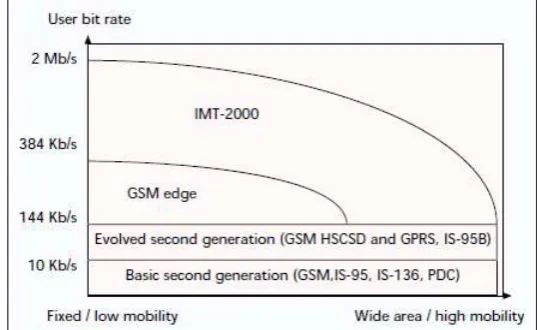
Full coverage and mobility for 144 Kb/s, preferably 384 Kb/s
Limited coverage and mobility for 2 Mb/s
High spectrum efficiency compared to existing systems
High flexibility to introduce new services
The targets of third-generation systems are wide and, depending on the main driver, system solutions will be different. The maturity of second-generation mobile radio systems varies, ranging from over 40 percent penetration in Scandinavia to a very low penetration in developing countries, where the cellular systems are in the beginning of their lifecycle. Therefore, it is clear that the need to develop a new system varies, and the different views and needs may result in several different variants of IMT-2000. In addition, different backward compatibility requirements influence the technology applied to third-generation systems.
Main regional standards bodies have already decided the preferred technology for IMT-2000. The fast development during recent years has been due to the Japanese initiative. In the beginning of 1997, the Association for Radio Industry and Business (ARIB), a standardization body responsible for Japan’s radio standardization, decided to proceed with detailed standardization of wideband CDMA. The technology push from Japan accelerated standardization in Europe and the United States. During 1997 joint parameters for Japanese and European wideband CDMA proposals were agreed upon. The air interface is now commonly referred as WCDMA. In January 1998, strong support behind wideband CDMA led to the selection of WCDMA as the UMTS terrestrial air interface scheme for FDD frequency bands in ETSI. The selection of wideband CDMA was also backed by Asian and American GSM operators. For TDD bands, a time division CDMA (TD-CDMA) concept was selected. In the United States in March 1998, the TIA (Telecommunications Industry Association) TR45.5 committee, responsible for IS-95 standardization, adopted a framework for wideband CDMA backward compatible to IS-95, called cdma2000. TR45.3, responsible for IS-136 standardization, adopted a TDMA-based third-generation proposal, UWC-136 (Universal Wireless Communications), based on the recommendation from the UWCC in February 1998. Korea is still considering two wideband CDMA technologies, one similar to WCDMA and the other similar to cdma2000.
The preferred technology for third-generation systems depends on technical, political, and business factors. Technical factors include issues such as provision of required data rates, and performance. Political factors involve reaching agreement between standards bodies and taking into account the different starting points of different countries and regions. On one hand, the investments into the existing systems motivate a backward compatibility approach. On the other, new business opportunities or the possibility of changing the current situation might motivate a new approach.
This article is organized as follows. The past, present, and future activities of CDMA are presented in the next section. The following section explains the basic concepts and elements of CDMA. Then the IS-95 air interface is introduced according to the new IS-95 standard, followed by a brief discussion of air interface technologies for third-generation, with a short description of TD-CDMA. Wideband CDMA schemes are then discussed in great length and conclusions are given in the final section.
Figure 1. IMT-2000 user bit rate vs. coverage and
mobility.
2. Proposed Work:
1.2 CDMA: Past, Present, and Future:
The origins of spread spectrum are in military field and navigation systems. Techniques developed to counteract intentional jamming have also proved suitable for communication through dispersive channels in cellular applications. In this section we highlight the milestones for CDMA development starting from the 1950s after the invention of the Shannon theorem [6]. An extensive overview of spread spectrum history
is given in [7].
spread spectrum signal and combined by the RAKE receiver. The near-far problem (i.e., a high interference overwhelming a weaker spread spectrum signal) was first mentioned in 1961 by Magnuski [7]. For cellular application spread spectrum was suggested by Cooper and Nettleton in 1978 [9]. During the 1980s Qualcomm investigated DS-CDMA techniques, which finally led to the commercialization of cellular spread spectrum communications in the form of the narrowband CDMA IS-95 standard in July 1993. Commercial operation of IS-95 systems started in 1996. Multi user detection (MUD) has been subject to extensive research since 1986 when Verdu formulated optimum multi user detection for the additive white Gaussian noise (AWGN) channel, maximum likelihood sequence estimator (MLSE) [10].
During the 1990s wideband CDMA techniques with a bandwidth of 5 MHz or more have been studied intensively throughout the world, and several trial systems have been built and tested [4]. These include FRAMES Multiple Access (FRAMES FMA2) in Europe, Core-A in Japan, the European/Japanese harmonized WCDMA scheme, cdma2000 in the United States, and the Telecommunication Technology Association I and II (TTA I and TTA II) schemes in Korea. Introduction of third-generation wireless communication systems using wideband CDMA is expected around the year 2000.
Based on the above description, the CDMA era is divided in three periods: the pioneer CDMA era, the narrowband CDMA era, and the wideband CDMA era, as shown in Table 1.
1.3 CDMA Concepts:
In CDMA each user is assigned a unique code sequence it uses to encode its information-bearing signal. The receiver, knowing the code sequences of the user, decodes a received
signal after reception and recovers the original data. This is possible since the cross correlations between
the code of the desired user and the codes of the other users are small. Since the bandwidth of the code signal is chosen to be much larger than the bandwidth of the information-bearing signal, the encoding process enlarges (spreads) the spectrum of the signal and is therefore also known as spread-spectrum modulation. The resulting signal is also called a spread-spectrum signal, and CDMA is often denoted as spread-spectrum multiple access (SSMA) [1–3, 11–12].
The spectral spreading of the transmitted signal gives to CDMA its multiple access capability. It is therefore important to know the techniques necessary to generate spread-spectrum signals and the properties of these signals. A spread-spectrum modulation technique must be fulfill two criteria:
The transmission bandwidth must be much larger than the information bandwidth.
The resulting radio-frequency bandwidth is determined by a function other than the information being sent (so the bandwidth is statistically independent of the information signal). This excludes modulation techniques like frequency modulation (FM) and phase modulation (PM).
The ratio of transmitted bandwidth to information bandwidth is called the processing gain, Gp, of the spread-spectrum system,
…….1
where Bt is the transmission bandwidth and Bi is the bandwidth of the information-bearing signal.
The receiver correlates the received signal with a synchronously generated replica of the spreading code to recover the original information-bearing signal. This implies that the receiver must know the code used to modulate the data.
Because of the coding and the resulting enlarged bandwidth, SS signals have a number of properties that differ from the properties of narrowband signals. The most interesting ones, from the communication systems point of view, are discussed below. To have a clear understanding, each property has been briefly explained with the help of illustrations, if necessary, by applying direct sequence spread-spectrum techniques.
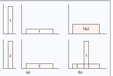
the desired user will be larger than the interfering power provided there are not too many interferers, and the desired signal can be extracted. The multiple access capability is illustrated in Fig. 2. In Fig. 2a, two users generate a spread-spectrum signal from their narrowband data signals. In Fig. 2b both users transmit their spread-spectrum signals at the same time. At the receiver 1 only the signal of user 1 is “despread” and the data recovered.
Figure 2. Principle of spread-spectrum multiple access
1.3.2 Protection against Multipath Interference:
In a radio channel there is not just one path between a transmitter and receiver. Due to reflections (and refractions) a signal will be received from a number of different paths. The signals of the different paths are all copies of the same transmitted signal but with different amplitudes, phases, delays, and arrival angles. Adding these signals at the receiver will be constructive at some of the frequencies and destructive at others. In the time domain, this results in a dispersed signal. Spread-spectrum modulation can combat this multipath interference; however, the way in which this is achieved depends very much on the type of modulation used. In the next section, where CDMA schemes based on different modulation methods are discussed, we show for each scheme how multipath interference rejection is obtained.
1.3.3 Privacy: The transmitted signal can only be despread and the data recovered if the code is known to the receiver.
1.3.4 Interference Rejection: Cross-correlating the code signal with a narrowband signal will spread the power of the narrowband signal thereby reducing the interfering power in the information bandwidth. This is illustrated in Fig. 3. The spread-spectrum signal (s) receives narrowband interference (i). At the receiver the SS signal is “despread” while the interference signal is spread, making it appear as background noise compared to the despread signal.
1.3.5 Anti-Jamming Capability, Especially Narrowband Jamming: This is more or less the same as interference rejection except the interference is now willfully inflicted on the system. It is this property, together with the next one, that makes spread-spectrum modulation attractive for military applications.
1.3.6 Low Probability of Interception (LPI):
Because of its low power density, the spread-spectrum signal is difficult to detect and intercept by a hostile listener.
A general classification of CDMA is given in Fig. 4. There are a number of modulation techniques that generate spread spectrum signals. We briefly discuss the most important ones.
Direct sequence spread-spectrum: The information bearing signal is multiplied directly by a high chip rate code signal.
Frequency hopping spread-spectrum: The carrier frequency at which the information-bearing signal is transmitted is rapidly changed according to the code signal
Time hopping spread-spectrum: The information-bearing signal is not transmitted continuously. Instead the signal is transmitted in short bursts where the times of the bursts are decided by the code signal.
Hybrid modulation: Two or more of the above-mentioned SS modulation techniques can be used together to combine the advantages and, it is hoped, to combat their disadvantages. Furthermore, it is possible to combine CDMA with other multiple access methods: TDMA, multi carrier (MC), or multi tone (MT) modulation. In the case of MC-CDMA, spreading is done along the frequency axis, while for MT-CDMA spreading is done along the time axis. Note that MC-CDMA and MT-CDMA are based on orthogonal frequency division multiplexing (OFDM).
Figure 4. Classification of CDMA
1.4 Spread - Spectrum:
1.4.1 Multiple access Direct Sequence: In DSCDMA the modulated information bearing signal (the data signal) is directly modulated by a digital, discrete-time, discrete-valued code signal. The data signal can be either analog or digital; in most cases it is digital. In the case of a digital signal the data modulation is often omitted and the data signal is directly multiplied by the code signal and the resulting signal modulates the wideband carrier. It is from this direct multiplication that the direct sequence CDMA gets its name.
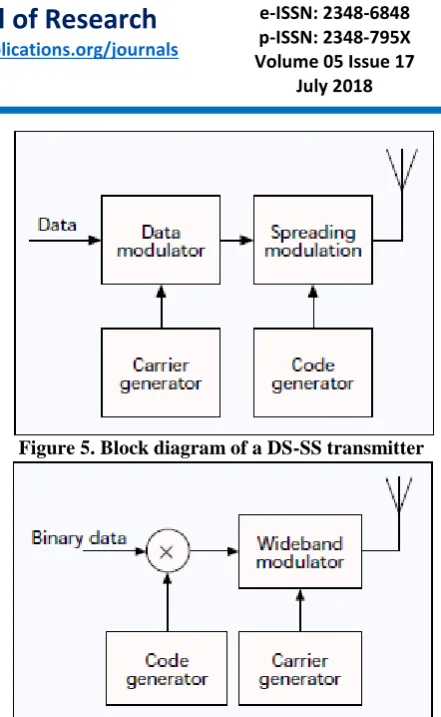
In Fig. 5 a block diagram of a DS-CDMA transmitter is given. The binary data signal modulates a RF carrier. The modulated carrier is then modulated by the code signal. This code signal consists of a number of code bits called “chips” that can be either +1 or –1. To obtain the desired spreading of the signal, the chip rate of the code signal must be much higher than the chip rate of the information signal. For the code modulation various modulation techniques can be used, but usually some form of phase shift keying (PSK) like binary phase shift keying (BPSK), differential binary phase shift keying (D-BPSK), quadrature phase shift keying (QPSK), or minimum shift keying (MSK) is employed.
If we omit the data modulation and use BPSK for the code modulation, we get the block diagram given in Fig. 6. The DS-SS signal resulting from this transmitter is shown in Fig. 7. The rate of the code signal is called the chip rate; one chip denotes one symbol when referring to spreading code signals. In this figure, 10 code chips per information symbol are transmitted (the code chip rate is 10 times the data rate) so the processing gain is equal to 10.
Figure 5. Block diagram of a DS-SS transmitter
Figure 6. Modified block diagram of a DSSS transmitter.
1.4.2 FREQUENCY HOPPING: In frequency hopping CDMA, the carrier frequency of the modulated information signal is not constant but changes periodically. During time intervals T the carrier frequency remains the same, but after each time interval the carrier hops to another (or possibly the same) frequency. The hopping pattern is decided by the code signal. The set of available frequencies the carrier can attain is called the hop-set.
The frequency occupation of an FH-SS system differs considerably from a DS-SS system. A DS system occupies the whole frequency band when it transmits, whereas an FH system uses only a small part of the bandwidth when it transmits, but the location of this part differs in time.
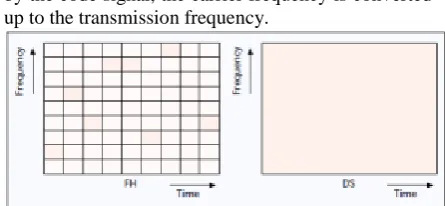
The difference between the FH-SS and the DH-SS frequency usage is illustrated in Fig. 9. Suppose an FH system is transmitting in frequency band 2 during the first time period. A DS system transmitting in the same time period spreads its signal power over the whole frequency band so the power transmitted in frequency band 2 will be much less than that of the FH system. However, the DS system transmits in frequency band 2 during all time periods while the FH system only uses this band part of the time. On average, both systems will transmit the same power in the frequency band.
by the code signal, the carrier frequency is converted up to the transmission frequency.
Figure 9. Time/frequency occupancy of FH and DS signals.
1.4.3 Multiple Access: It is easy to visualize how the F-FH and S-FH CDMA obtain their multiple access capability. In the F-FH one symbol is transmitted in different frequency bands. If the desired user is the only one to transmit in most of the frequency bands, the received power of the desired signal will be much higher than the interfering power and the signal will be received correctly.
In the S-FH multiple symbols are transmitted at one frequency. If the probability of other users transmitting in the same frequency band is low enough, the desired user will be received correctly most of the time. For those times that interfering users transmit in the same frequency band, error-correcting codes are used to recover the data transmitted during that period.
1.4.4 MULTIPATH INTERFERENCE: In the F-FH CDMA the carrier frequency changes a number of times during the transmission of one symbol. Thus, a particular signal frequency will be modulated and transmitted on a number of carrier frequencies. The multipath effect is different at the different carrier frequencies. As a result, signal frequencies that are amplified at one carrier frequency will be attenuated at another carrier frequency and vice versa. At the receiver the responses at the different hopping frequencies are averaged, thus reducing the multipath interference. Since usually noncoherent combining is used, this is not as effective as the Multipath interference rejection in a DS-CDMA system, but it still gives quite an improvement.
1.4.5 Narrowband Interference: Suppose a narrowband signal is interfering on one of the hopping frequencies. If there are Gp hopping frequencies (where Gp is the processing gain), the desired user will (on the average) use the hopping frequency where the interferer is located 1/Gp percent of the time. The interference is therefore reduced by a factor Gp.
1.4.6 LPI: The difficulty in intercepting an FH signal lies not in its low transmission power. During a
transmission, it uses as much power per hertz as a continuous transmission. But the frequency at which the signal is going to be transmitted is unknown, and the duration of the transmission at a particular frequency is quite small. Therefore, although the signal is more readily intercepted than a DS signal, it is still a difficult task to perform.
Apart from the above-mentioned properties, the FHCDMA has a number of other specific properties that we can divide into advantageous (+) and disadvantageous (-) behavior:
+Synchronization is much easier with FH-CDMA than with DS-CDMA. With FH-CDMA synchronization has to be within a fraction of the hop time. Since spectral spreading is not obtained by using a very high hopping frequency but by using a large hop-set, the hop time will be much longer than the chip time of a DS-CDMA system.
Thus, an FH-CDMA system allows a larger synchronization error.
+The different frequency bands that an FH signal can occupy do not have to be contiguous because we can make the frequency synthesizer easily skip over certain parts of the spectrum. Combined with the easier synchronization, this allows much higher spread-spectrum bandwidths.
+The probability of multiple users transmitting in the same frequency band at the same time is small. A user transmitting far from the base station will be received by it even if users close to the base station are transmitting, since those users will probably be transmitting at different frequencies. Thus, the near-far performance is much better than that of DS. +Because of the larger possible bandwidth a FH system can employ, it offers a higher possible reduction of narrowband interference than a DS system.
– A highly sophisticated frequency synthesizer is necessary.
– An abrupt change of the signal when changing frequency bands will lead to an increase in the frequency band occupied. To avoid this, the signal has to be turned off and on when changing frequency.
– Coherent demodulation is difficult because of the problems in maintaining phase relationships during hopping.
slots, the frequency it needs for its transmission has increased by a factor M. A block diagram of a TH-CDMA system is given in Fig. 11. Figure 12 shows the time-frequency plot of the TH-CDMA systems. Comparing Fig. 12 with Fig. 9, we see that the TH-CDMA uses the whole wideband spectrum for short periods instead of parts of the spectrum all of the time. Following the same procedure as for the previous CDMA schemes, we discuss the properties of TH-CDMA with respect to multiple access capability, Multipath interference rejection, narrowband interference rejection, and probability of interception.
Multiple access — The multiple access capability of THSS signals is acquired in the same manner as that of the FH-SS signals; namely, by making the probability of users’ transmissions in the same frequency band at the same time small. In the case of time hopping all transmissions are in the same frequency band, so the probability of more than one transmission at the same time must be small. This is again achieved by assigning different codes to different users. If multiple transmissions do occur, error-correcting codes ensure that the desired signal can still be recovered. If there is synchronization among the users, and the assigned codes are such that no more than one user transmits at a particular slot, then the THCDMA reduces to a TDMA scheme where the slot in which a user transmits is not fixed but changes from frame to frame.
Multipath interference — In the time hopping CDMA, a signal is transmitted in reduced time. The signaling rate, therefore, increases and dispersion of the signal will now lead to overlap of adjacent bits. Therefore, no advantage is to be gained with respect to Multipath interference rejection.
Narrowband interference — A TH-CDMA signal is transmitted in reduced time. This reduction is equal to 1/Gp, where Gp is the processing gain. At the receiver we will only receive an interfering signal during the reception of the desired signal. Thus, we only receive the interfering signal 1/Gp percent of the time, reducing the interfering power by a factor Gp.
LPI — With TH-CDMA the frequency at which a user transmits is constant but the times at which a user transmits are unknown, and the durations of the transmissions are very short. Particularly when multiple users are transmitting, this makes it difficult for an intercepting receiver to distinguish the beginning and
end of a transmission and to decide which transmissions belong to which user.
Apart from the above-mentioned properties, the THCDMA has a number of other specific properties that we can divide into advantageous (+) and disadvantageous (-) behavior:
+Implementation is simpler than that of FH-CDMA. +It is a very useful method when the transmitter is average- power limited but not peak-power limited since the data are transmitted is short bursts at high power.
+As with the FH-CDMA, the near-far problem is much less of a problem since TH-CDMA is an avoidance system, so most of the time a terminal far from the base station transmits alone, and is not hindered by transmissions from stations close by. – It takes a long time before the code is synchronized, and the time in which the receiver has to perform the synchronization is short.
– If multiple transmissions occur, a large number of data bits are lost, so a good error-correcting code and data interleaving are necessary.
Figure 11. Block diagram of an TH-CDMA transmitter and receiver
2.
Methodology
Introduction:
Number of Errors) of Pulse Shaping FIR Filter at different group delay for WCDMA.
Digital Signal processing techniques are being used to improve the performance of 3G systems. WCDMA (Wideband Code-Division Multiple Access), an ITU standard derived from Code-Division Multiple Access (CDMA), is officially known as IMT-2000 direct spread spectrum.W-CDMA is a third-generation (3G) mobile wireless technology that promises much higher data speeds to mobile and portable wireless devices than commonly offered in today's market. W-CDMA can support mobile/portable voice, images, data, and video communications at up to 2 Mbps (local area access) or 384 Kbps (wide area access).Wideband Code-division multiple access is one of several methods of multiplexing wireless users. In CDMA, users are multiplexed by distinct codes rather than by orthogonal frequency bands, as in frequency-division multiple access. The enhancement in performance is obtained from a Direct Sequence Spread Spectrum (DSSS) signal through the processing gain and the coding gain can be used to enable many DSSS signals to occupy the same channel bandwidth, provided that each signal has its own pseudorandom (signature) sequence [1-7]. Thus enable several users to transmit their information over the same channel bandwidth. This is the main concept of a WCDMA communication system. The signal detection is accomplished at the receiver side by knowing the code sequence or signature of the desired user. Since the bandwidth of the code signal is chosen to be much larger than the bandwidth of the information-bearing signal, the encoding process enlarges or spreads the spectrum of the signal. Therefore, it is also known as spread spectrum modulation. The resulting signal is also called a spread-spectrum signal, and CDMA is often denoted as spread-spectrum multiple access. A tradeoff exists between bandwidth containment in frequency domain and ripple attenuation in time domain. It is this tradeoff of bandwidth containment versus ripple amplitude which must be considered by design engineers, when developing a data transmission system that employs pulse shaping.
To satisfy the ever increasing demands for higher data rates as well as to allow more users to simultaneously access the network, interest has peaked in what has come to be known as WCDMA The WCDMA has emerged as the most widely adopted 3G air interface and its specification has been created in 3GPP .In this system the user information bits are spread over much wider bandwidth by multiplying the user data bits with quasi random bits called as chips derived from CDMA spreading codes. In order to support very high bit rates (up to 2 Mbps) the use of variable spreading factor and multimode connection is
supported. The chip rate of 3.84Mcps/sec is used to lead a carrier bandwidth of 5Mhz.WCDMA also supports high user data rates and increased multipath diversity[8].Here each user is allocated the frames of 10 ms duration during which the user data is kept constant though data capacity among users can change from frame to frame.
2.2 Need of Efficient Pulse Shaping:
In communications systems, two important requirements of a wireless communications channel demand the use of a pulse shaping filter. These requirements are:
1) Generating band limited channels, and 2) Reducing inter symbol interference
(ISI) arising from multi-path signal reflections. Both requirements can be accomplished by a pulse shaping filter which is applied to each symbol. In fact, the sync pulse, shown below, meets both of these requirements because it efficiently utilizes the frequency domain to utilize a smaller portion of the frequency domain, and because of the windowing affect that it has on each symbol period of a modulated signal. [9-10]
2.3 Pulse Shaping in WCDMA:
Code-division multiple access is one of several methods of multiplexing wireless users. In CDMA, users are multiplexed by distinct codes rather than by orthogonal frequency bands, as in frequency-division multiple access. The enhancement in performance obtained from a direct sequence spread spectrum (DSSS) signal through the processing gain and the coding gain can be used to enable many DSSS signals to occupy the same channel bandwidth, provided that each signal has its own pseudorandom (signature) sequence. Thus enable several users to transmit there information over the same channel bandwidth. This is the main concept of a CDMA communication system. The signal detection is accomplished at the receiver side by knowing the code sequence or signature of the desired user. Since the bandwidth of the code signal is chosen to be much larger than the bandwidth of the information-bearing signal, the encoding process enlarges or spreads the spectrum of the signal. Therefore, it is also known as spread spectrum modulation. The resulting signal is also called a spread-spectrum signal, and CDMA is often denoted as spread-spectrum multiple access. The processing gain factor is defined as the ratio of the transmitted bandwidth to information bandwidth and is given by:
Gp=Bt/Bi. ………(1)
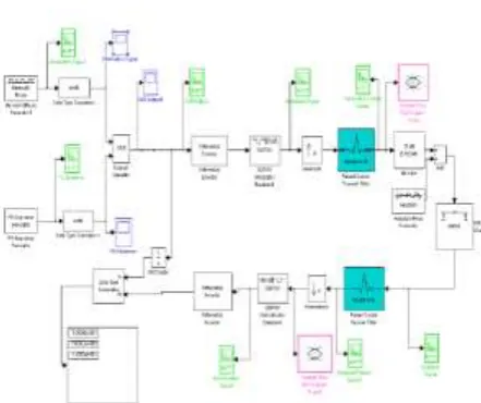
2.4 Simulation Model for WCDMA:
The WCDMA communication link proposed in this section is shown in Figure 1. The performance in terms of the Bit Error Rate can be examined for different values of Group Delay D of the pulse shaping filter against a sinusoidal interference. A simulink model based on the Matlab 7.3 version will provide the output. The information signal in wideband CDMA system is generated by Bernoulli Binary Generator and the PN sequence is used for spreading the signal at 5 MHz bandwidth. The signal is passed from different parameters block as shown in figure 1 and at the end BER is calculated by comparing the transmitted data and received data. On the basis of above block diagram, a simulation model has been developed by using Matlab Simulink Library as shown in figure 2.
Fig. 2.1: Block diagram for WCDMA System
Fig. 2: WCDMA based Simulation Model developed for Square Root Raised Cosine Pulse
2.4.1 Description of Different Element Blocks used in making WCDMA Simulation Model:
(1) Bernoulli Binary Generator. Bernoulli Binary Generator is used to generate information signal appropriate with the standard for WCDMA from simulink library. Bernoulli Binary Generator block as shown in figure generates random binary numbers using Bernoulli Distribution. The Bernoulli distribution has mean value 1-p and variance p(1-p).The probability of a zero parameter specifies p and can be any real number between zero and one. fig. 3 shows the block source parameters of Bernoulli Binary Generator
3.
Results and Discussion:
The simulation study has also been carried out for different values of D i.e.2,4,6 and 8. The simulation results for BER along with the number of errors and number of bits in each frame have been obtained and are summarized in tables 1, 2, 3,4
.
Table 1: Results for Group Delay D=2
Table 3: Results for Group Delay D=6
Table 4: Results for Group Delay D=8
The readings of the simulation model for number of bits, number of errors and Bit Error Rate at different values of D have been taken at different time instants during the simulation runs. The parameters of the simulation model are given as below: Eb/No=5dB;
PN Sequence Generator Sample
time=1/3840kbps,Bernoulli Binary Generator Sample time=1/64kbps(data services) Interpolation Factor M=5,Roll Off Factor =0.22(Optimum)[8]. Fig.8 shows effect of change of group delay on number of errors in the simulation study.
4.
Conclusion
5. The present study has proposed the WCDMA communication link employing the pulse shaping filters using matlab simulink. The group delay plays a crucial role in pulse shaping digital finite impulse response filter. The value of group delay should be minimal for efficient performance of digital pulse shaping filter. The effects of change in group delay on number of errors have been studied for square root raised cosine pulse shaping filter at 5 MHz bandwidth.
The study will be useful to improve the performance of WCDMA based network by using the modified and improved design of square root raised cosine pulse shaping filter. Design of new type of filter of higher or different order will be useful to get better root raised cosine approximation thereby improving the performance parameters like increased Capacity, reduced BER, better S/N ratio, and Reduced ISI (noise) as a consequence of pulse shaping. The future work will involve the incorporation of interpolation factor for tradeoff between D and M at fix roll off factor as well as study of parameters of pulse shaping filter on the bit error rate performance analysis for WCDMA based wireless communication.
5.
References
• [1] R.M Piedra and A.Frish, “Digital Signal Processing Comes of Age”, IEEE Spectrum, Vol.33, No.5, May 1996.
• [2] J. Stevens, “DSPs in Communication,” IEEE Spectrum Vol.35, No.9, pp. 39-46, Sept.98.
• [3] C.Iniaco and D.Embres,””The DSP Decision-Fixed Or Floating?”, IEEE Spectrum, Vol.3, No.9, pp.72-74,1996.
• [4] P.M.Grant, ”Signal Processing Hardware and Software”, IEEE signal Processing Magazine,vol13,No.1, pp: 86-92, Jan 1992.
• [5] G.Giannkis, ”Highlights of Signal Processing for Communications”, IEEE Signal Processing Magazine, Vol 16, No.2,14-51, March,1999.
• [6] C. Richard Johnson and William A. Sethares, Telecommunications Breakdown.
• [7] John G. Proakis and Masoud Salehi, Communications Systems Engineering.
• [8] Simon Haykin, “Communications Systems” , Tata McGraw Hill.
• [9] B.P. Lathi, Modern Digital and analog Communications Systems, John Wiley & Sons.
• [10] John G. Proakis, Digital Communications. McGraw Hill.
• [11] KenGentile,”The care and feeding of
digital pulse shaping