THE CALCULATION OF ANGULAR SIDE-PLAY AMOUNT PRODUCED BY RADIATION PRESSURE ACTING ON THE SPACE OBJECT
Y.-Q. Zhang and Z.-S. Wu
Shchool of Science Xidian University
Xi’an, Shaanxi 710071, China
Abstract—In this paper, the angular side-play amount created by radiation pressure acting on active space object has been detailed investigated based on the physical optics, and the results are compared with the results by Mie theory; the correctness of the physical optics model is validated. The curves of angular side-play amount varied with the energy density of incident wave, mass of the object, and the angular between the direction of incident wave and initial velocity of the space etc. Using the results having been calculated, we analyzed the detectable conditions of angular side-play amount. A new method, which identifies different active object in space, has been taken out.
1. INTRODUCTION
With the development of science technology, especially military aviation, more and more aircrafts come into space. These aircrafts play an important role in the field of military and civil applications. The space objects include the strategic missile, satellite, space vehicle, space station etc which the object height is about 100 km above [2]. On the human space moving, space detection and identify technologies are absolutely necessarily. At present, the characters of electromagnetic, light wave scatter and radiation of the objects are managed on the process of space target detection identify [1–17]. Whereas, the development of the detection and identify study using the target’s motility is not abroad.
astrophysics [20, 21] and the target’s altitude control [22, 23]. Here, we study the target identification using radiation pressure. For several objects out of atmosphere, the flight speeds are the same due to no atmospheric drag. But their masses are different. In general, the direction of the target motion is different from the direction of the radiation pressure, so the direction of the target motion must deviate. In the same conditions, the side-play amounts of different mass targets are different. Detecting these different side-play amounts, we can identify the different targets.
In this paper, the expression of the radiation pressure for giant targets out of atmosphere is deduced in the condition of plane wave incidence and discarding the atmospheric action based on the physical optics. Also the angular side-play amount created by radiation pressure acting on the object has been detailed investigated. The correctness of the result is validated by the exact solution created by Mie theory. And the identifiable conditions are analyzed.
2. THE RADIATION PRESSURE FOR THE SURFACE OF THE TARGET
2.1. The Method of Mie Theory [20, 21]
The cross-section of radiation pressure created by plane wave acting on isotropic dielectric sphere can be calculated based on Mie theory. The expression is:
Cpr = 2π k2Re
∞
n=1
{(2n+ 1)(an+bn)
+2n(n+ 2)
n+ 1
ana∗n+1+bnb∗n+1
+2(2n+ 1)
n(n+ 1)anb
∗
n
= Cext−Csca<cosθ > (1)
Here an, bn are Mie coefficients, k = 2λπ,Cext is the extinction cross-section, Csca is the scattering cross-section, and < cosθ > is the average cosine of the scattering angle.
The radiation force which the target experiences at the incidence direction is:
F = 1
cI
incC
pr (2)
c= 1/√ε0µ0 is the velocity in the air void. Iinc= 12
(ε0/µ0)|E0|2 is
2.2. The Method of Physical Optics [18, 19]
Considering that monochromatic plane wave incidents to the surface of the target from the atmosphere, the dielectric constant and the magnetic conductivity of the atmosphere are ε0, µ0, and dielectric
constant and the magnetic conductivity of the target are ε, µ. ˆn
is normal unit vector from the space to the surface of the target. The component on ˆn direction of the electromagnetic force acting on unit surface of the target, namely electromagnetic pressure acting on dielectric surface is:
p=−n·(T2−T1) = 1 2ε0
E22n−E12n− 1
2µ0
B22t−B21t (3) Here E1n, E2n, B1t, B2t are normal electric-field intensity and tangential magnetic induction intensity of the incident wave and scattered wave respectively.
Supposing that:
E, B: field due to the incident plane wave;
E, B: field due to the reflection of the incident plane wave by the surface of the object;
E, B: field due to the refraction of the incident plane wave by the object.
Considering boundary problem relation of the field quantity, the Equation (3) can be expressed:
p= 1 2ε0
E2−(E+E)2
− 1
2µ0
B2−(B+B)2
(4) This is the general expression of the radiation pressure for the surface of the target.
1) The radiation pressure of the conductor’s surface
For ideal conductor, the constituents of each field quantities can be obtained based on the relations of the monochromatic plane wave
E and B and the boundary value conditions. And substitute the constituents of each field quantities to function (2), we can obtain the radiation pressure of the conductor’s surface:
p= 2ε0E02cos2θcos2(kxsinθ−ωt)
Carry out time average for above formulation, we get:
p=ε0E02cos2θ (5)
the energy density of the reflect wave ¯wr. In the condition of total reflection, it equates double of the energy density of the incident wave:
¯
w= 2 ¯wi = 2· 1 2ε0E
2
0 =ε0E02
So, the radiation pressure of the conductor’s surface [18] is:
p= ¯wicos2θ (6)
2) The radiation tension of the dielectric surface
The wave field of the reflect wave and the refracted wave can be obtained if the refractive index of the dielectric and the incident plane wave are known. Supposing that refractive index of the dielectric is
n, n = ε/ε0 = sinθ/sinθ and the incident face is x-y plan, the dielectric surface is z = 0 plan, n = ez, and it directs to dielectric inner from the dielectric outer. Base on the Fresnel reflection formula, the fields of the incident wave, the reflect wave and the refracted wave are:
E=E0(−cosθex+ sinθez) cos(k·r−ωt) (7)
E=E0tg(θ−θ )
tg(θ+θ)(cosθex+ sinθez) cos(k
·r−ωt) (8)
E=E0
2 cosθsinθ
sin(θ+θ) cos(θ−θ)×(−cosθ
e
x+sinθez) cos(k·r−ωt) (9) Substitute the constituents of each field quantities to function (4),
P = 2εE02 cos
2θ(sin4θ−sin4θ)
sin2(θ+θ) cos2(θ−θ)cos
2(kxsinθ−ωt)
= 4 ¯w cos
2θ(sin4θ−sin4θ)
sin2(θ+θ) cos2(θ−θ)cos
2(kxsinθ−ωt)
And carrying out time average, we can obtain the radiation tension of the dielectric surface:
P = 2 ¯w cos
2θ(sin4θ−sin4θ)
sin2(θ+θ) cos2(θ−θ) (10)
3. THE ANGULAR SIDE-PLAY AMOUNT OF THE
TARGET
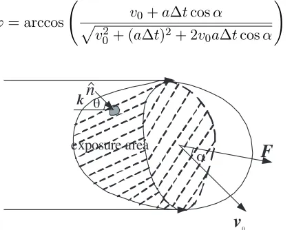
plane wave acts on the target. Considering a large-scale target exposed completely by the plane wave, using the method of physical optics to compute the radiation pressure, the effecting in the exposure area is only considered. In practical process, grid dividing of the object’s surface is necessary firstly, and then the force acting on every grid is calculated. After all, carries on the vectorial resultant to these force, by now the resultant force which the target receives is obtained.
Supposing the radiation pressure acting on some unit of area is
pi, as shown in Figure 1, and then the external force which the target receives is:
F = m
i=1
pisi (11)
m is the amount of the unit of area,si is the area ofith unit of area. Then the angular side-play amount of the target is calculated based on kinematics equation:
ϕ= arccos v0+a∆tcosα
v02+ (a∆t)2+ 2v0a∆tcosα
(12)
v
exposure areaθ
0 α
n
k
F
Figure 1. The radiation pressure acting on random object.
4. INTERPRETATION OF RESULT
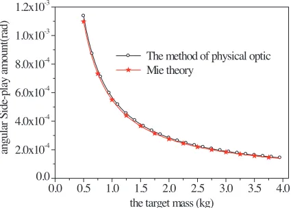
4.1. Comparing the Results of between Mie Theory and the Method of Physical Optics
0.0 0.5 1.0 1.5 2.0 2.5 3.0 3.5 4.0 0.0
2.0x10⁻⁴ 4.0x10⁻⁴ 6.0x10⁻⁴ 8.0x10⁻⁴ 1.0x10⁻³ 1.2x10⁻³
an
gul
ar
S
ide
-p
la
y
am
ount
(r
ad)
the target mass (kg)
The method of physical optic Mie theory
Figure 2. Calculated results by Mie theory and the method of physical optics.
computational condition. From the figure we know that two results are consilient basically. Only the result calculated by the method of physical optics is little larger than the result calculated by Mie theory because the grid dividing of the surface is adopted (here the tetragonal surface element is used), the calculated area is larger than the real area in the method of physical optics.
4.2. Analyses of Some Cases
Because the subtotal space targets are outside several hundred kilo-meters above atmosphere, the atmospheric influence isn’t considered when we calculate the angular side-play amount. Using the method of physical optics presented above, we calculate the variational regularity of the angular side-play amount of the metal and media sphere, column due to the effect of radiation pressure generated by incident wave.
0.5 1.0 1.5 2.0 2.5 3.0 3.5 4.0 0.0
1.0x10⁻⁴ 2.0x10⁻⁴ 3.0x10⁻⁴ 4.0x10⁻⁴ 5.0x10⁻⁴
angular Side-play amount(rad)
the mass of the dielectric-sphere (kg)
ϖ=0.5(J/m3)
ϖ=1(J/m3)
ϖ=2(J/m3)
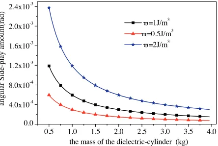
Figure 3. Variation of angular side-play amount along with mass of the dielectric-sphere.
0.5 1.0 1.5 2.0 2.5 3.0 3.5 4. 0.0
4.0x10⁻⁴ 8.0x10⁻⁴ 1.2x10⁻³ 1.6x10⁻³ 2.0x10⁻³ 2.4x10⁻³
0
angular Side-play
amount(rad)
the mass of the dielectric-cylinder (kg)
ϖ=1J/m3
ϖ=0.5J/m3
ϖ=2J/m3
Figure 4. Variation of angular side-play amount along with mass of the dielectric-cylinder.
we know that the angular side-play amount increases along with the incident wave energy density increasing, but reduces along with the mass of the targets increasing, also it increases along with the accretion of angle between the direction of the incident wave and the initial rate of the target, and when the mass of the target is given, it increases along with the size of the target increasing. These change rule can be explained completely by the radiation pressure formula and the kinematics equation.
0.0 0.5 1.0 1.5 2.0 2.5 3.0 3.5 4.0 4.5 0.0
2.0x10⁻³ 4.0x10⁻³ 6.0x10⁻³ 8.0x10⁻³ 1.0x10⁻² 1.2x10⁻² 1.4x10⁻²
angular Side-play amount(rad)
energy density of the incident waveϖ(J/m3)
sphere θ=300 sphere θ=600 sphere θ=450 cylinderθ=300 cylinderθ=600 cylinderθ=450
Figure 5. Variation of the metallic target’s angular side-play amount along with energy density of the incident wave.
0.0 0.5 1.0 1.5 2.0 2.5 3.0 3.5 4.0 0.0
5.0x10⁻³ 1.0x10⁻² 1.5x10⁻² 2.0x10⁻² 2.5x10⁻² 3.0x10⁻² 3.5x10⁻² 4.0x10⁻²
angular
Side-play amount (rad)
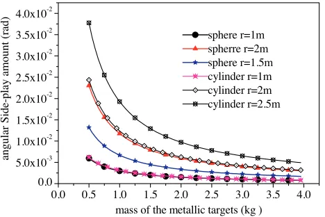
mass of the metallic targets (kg ) sphere r=1m spherre r=2m sphere r=1.5m cylinder r=1m cylinder r=2m cylinder r=2.5m
Figure 6. Variation of angular side-play amount along with mass of the metallic targets.
the energy density of the incident wave must be larger than 0.35 J/m3 (here the angular side-play amount is 0.0566◦) that the angular side-play amount can be detected. But for dielectric target, it’s angular side-play amount is 1 ∼ 2 order of magnitude less than the metallic target’s, and request more larger energy density of the incident wave. If the energy density of the incident wave is given, we also can increase angular side-play amount by increasing the angle of the incidence direction of the wave and the initial velocity of the targetα
to achieve the detectable conditions. For instance, if plane wave which the energy density is 0.3 J/m3incident the above-mentioned target, the
angleα must be lager than 50.92◦, then the angular side-play amount only can be bigger than 0.05◦, achieving the detecting request.
It is significant to calculate the angular side-play amount for identifying and detecting the target. If the sizes of the true and false targets are close, and their tracks are same, we can identify the true and false targets by the sizes of their angular side-play amounts, thus achieves the precision guidance.
5. CONCLUSION
In this paper, the variation of the angular side-play amounts created by radiation pressure produced by the plane wave acting on active space object along with the different parameters are calculated. And the conditions of the parameters satisfying the detector to be able to detect the target’s angular side-play amount are analyzed, such as giving the angular between the direction of incident wave and initial velocity of the space target, the smallest energy density of the incident plane wave which the detecting condition needs or the smallest angular between the direction of incident wave and initial velocity of the space target which can detect the variation of the targets when the energy density of the incident plane wave given. It is noteworthy that if the target’s parameters change, the detectable conditions are also different. And for actual question, we must analyze concretely.
REFERENCES
1. Gussenhoven, M. S. and E. G. Mullen, “Space radiation effects program: An overview,” IEEE Transactions on Nuclear Science, Vol. 40, No. 2, 221–227, 1993.
3. Wu, Z. and Y. Dou, “Scattering visible light and infrared radiation of spatial object,”Acta Optica Sinica, Vol. 23, No. 10, 1250–1254, 2003.
4. Chan, Y. K. and V. C. Koo, “An introduction to synthetic aperture radar (SAR),”Progress In Electromagnetics Research B, Vol. 2, 27–60, 2008.
5. Gavan, J., “Laser RADAR propagation range improved optimiza-tion for detecting and tracking cooperative targets,” Journal of Electromagnetic Waves and Applications, Vol. 5, No. 10, 1055– 1067, Oct. 1991.
6. Camps, A., J. Bara, F. Torres, and I. Corbella, “Extension of the clean technique to the microwave imaging of continuous thermal sources by means of aperture synthesis radiometers,” Progress In Electromagnetics Research, PIER 18, 67–83, 1998.
7. Cui, B., C. Wang, and X.-W. Sun, “Microstrip array double-antenna (MADA) technology applied in millimeter wave compact radar front-end,”Progress In Electromagnetics Research, PIER 66, 125–136, 2006.
8. Alivizatos, E. G., M. N. Petsios, and N. K. Uzunoglu, “Towards a range-doppler UHF multistatic radar for the detection of noncooperative targets with low RCS,”Journal of Electromagnetic Waves and Applications, Vol. 19, No. 15, 2015–2031, 2005. 9. Fabbro, V., P. F. Combes, and N. Guillet, “Apparent radar cross
section of a large target illuminated by a surface wave above the sea,”Progress In Electromagnetics Research, PIER 66, 41–60, 2005.
10. Mallahzadeh, A. R., M. Soleimani, and J. Rashed-Mohassel, “RCS computation of airplane using parabolic equation,” Progress In Electromagnetics Research, PIER 57, 265–276, 2006.
11. Haridim, M., H. Matzner, Y. Ben-Ezra, and J. Gavan, “Cooperative targets detection and tracking range maximization using multimode ladar/radar and transponders,” Progress In Electromagnetics Research, PIER 44, 217–229, 2004.
12. Aly, O. A. M. and A. S. Omar, “Detection and localization of rf radar pulses in noise environments using wavelet packet transform and higher order statistics,” Progress In Electromagnetics Research, PIER 58, 301–317, 2006.
14. Mooney, J. E., Z. Ding, and L. S. Riggs, “Performance analysis of a GLRT in late-time radar target detection,” Progress In Electromagnetics Research, PIER 24, 77–96, 1999.
15. Xu, X. and Y. Qin, “ISAR image modeling of aircraft with propeller blades,” Progress In Electromagnetics Research Symposium, Beijing, China, March 26–30, 2007.
16. Li, Y.-L., J.-Y. Huang, and M.-J. Wang, “The scattering cross section for a target irradiated by time-varying electromagnetic waves,” Journal of Electromagnetic Waves and Applications, Vol. 21, No. 9, 1265–1271, 2007.
17. Ruppin, R., “Scattering of electromagnetic radiation by a perfect electromagnetic conductor sphere,” Journal of Electromagnetic Waves and Applications, Vol. 20, 1569–1576, 2006.
18. Yuan, D., “Study on radiation pressure exerted on medium surface,” Journal of Hubei University, Natural Science Edition, Vol. 20, No. 1, 36–39, 1998.
19. Ma, S., “The alculation of rotation produced by radiation force of laser on cylinder,”Journal of Jiangxi Normal University, Vol. 23, No. 3, 230–234, 1999.
20. Mishchenko, M. I., “Radiation force caused by scattering, absorption, and emission of light by nonspherical particles,”Joural of Quantitative Spectroscopy&Radiative Transfer, 811–816, 2002. 21. Mishchenko, M. I., “Radiation pressure on randomly-oriented nonpherical particles,” Astrophysics and Space Science, Vol. 180, 163–169, 1991.
22. Singh, S. N. and W. Yim, “Nonlinear adaptive backstepping design for spacecraft attitude control using radiation pressure,” Conference on Decision and Control, 1239–1244, Las Vegas, Nevada, USA, Dec. 2002.