Development and Evaluation of BaFe
12O
19-PANI-MWCNT
Composite for Electromagnetic Interference (EMI) Shielding
Muhammad H. B. Zahari1, Beh Hoe Guan1, *, and Cheng Ee Meng2
Abstract—The salient individual properties of BaFe12O19, MWCNT, and PANI show promise in exhibiting excellent electromagnetic interference (EMI) shielding when they are combined. This research work focuses on developing a composite consisting of all three materials through a simple polymerization process and then evaluating its potential EMI shielding behaviour through electromagnetic measurements. The composite formation was morphologically and structurally verified through XRD, FTIR and FESEM measurements. The presence of main functional groups characteristic to PANI in the composite samples as shown by its FTIR spectra indicates its successful preparation through this method while FESEM micrographs show the random distribution of the composite constituents. The composite is conductive in nature with values reaching as high as 12.43 S/m for the composite with the highest MWCNT wt% (BPM 1 3 25). Electromagnetic measurements done at the X-band show promising EMI shielding behaviour in all prepared composites. The overall highest
SEAvalues are shown by sample BPM 1 3 25 with a minimum shielding value of 65 dB throughout the whole frequency band, far exceeding that of pure MWCNT.
1. INTRODUCTION
The search for economical and lightweight shielding materials continues with more focus put on studying various materials for both military and commercial applications [1–3]. Electromagnetic interference (EMI), a phenomenon in which disruptive electromagnetic energy is transmitted from one electronic device to another, used to be a major concern in military and radar technology. However, the rapid development of modern communication technology has exposed the commercial marketplace to the problem as more digital devices are made available to the general public. Since then, a lot of resources have been put into developing various methods of protection against EMI. A subset of the methods is the utilization of EMI shielding materials.
The current paradigm in developing shielding materials is to bring different materials with different salient electromagnetic properties together for the purpose of obtaining a single material that is able to exhibit optimum shielding properties, while taking advantage of the individual physical properties such as ease of fabrication and procurement, and also being cost effective. When evaluating the intrinsic parameters for the design of shielding materials, the following equation can be considered [4]:
A= 1/2σE2+ 1/2ωε0εrE2+ 1/2ωμ0μrH2 (1)
whereA(W/m3) is the electromagnetic energy absorbed per unit volume;E (V/m) is the electric field strength of the incident electromagnetic radiation;H(A/m) is the magnetic field strength of the incident electromagnetic radiation;σ(S/m) is the conductivity of the material;ω (sec−1) is the angular speed of
Received 10 October 2017, Accepted 17 November 2017, Scheduled 4 December 2017 * Corresponding author: Beh Hoe Guan ([email protected]).
the electromagnetic wave (ω = 2πf); ε0 (F/m) is the dielectric permittivity of vacuum: 8.854×10⁻¹²
(F/m);εris the complex permittivity of the material;μ0(A/m) is the magnetic permeability of vacuum:
1.2566×10⁻⁶ (A/m); andμr is the complex permeability of the material. As seen in Equation (1), the
absorbing capability of a medium relies on parameters such as conductivity, complex permittivity, and complex permeability. These components are especially important as they would determine a materials’ ability to dissipate energy through different magnetic and dielectric loss mechanisms. It is impossible to have a single shielding material that is able to encompass both magnetic and dielectric loss properties in one material. However, the combination of different materials is able to do so by combining it into composites.
Ferrites, especially the hexagonal type, have been considered as one of the most promising materials for microwave absorbing applications from the high demonstrated magnetic loss and wide absorption bandwidth. BaFe12O19, a member of the M-type hexagonal ferrite, is known for possessing high values of permeability in the microwave regions [5]. This is especially important as a higher value of complex permeability, especially its imaginary component, indicates a higher capability of the material to dissipate the absorbed electromagnetic energy in the form of heat through various magnetic loss mechanisms. Unfortunately, the practical application of BaFe12O19, as with other types of ferrites, is severely impeded by its heavy weight and low flexibility in molding it into complex structures [6]. This can be overcome by introducing an accompanying component that is lighter in weight and with considerable loss properties. Carbon-based materials lead this particular area with their light weight and higher surface area and have long been the subject of interest to be applied in many application as a result of their interesting properties. The conductive nature of multi-walled carbon nanotube (MWCNT) allows it to exhibit dielectric loss mechanisms. This, combined with the significantly larger value of its permittivity over other carbon allotropes makes MWCNT particularly appealing for EMI shielding applications. Despite this, the complex and costly fabrication process limits the widespread usage of MWCNT as a single shielding material [7]. A relatively cheaper supplementary component would be the family of conducting polymers. Polyaniline (PANI), a polymer belonging to this family, is particularly known for its economical and widely available precursor material, and relatively simple production methods. It functions similarly to that of MWCNT in which it is able to provide dielectric loss as a result of its high electrical conductivityσ. Despite both materials possessing significantly lighter weight than BaFe12O19, their application is limited due to poor magnetic loss and narrow absorbing bandwidth which again prevents the complete replacement of the magnetic component in a shielding material [8].
This research work details the integration of BaFe12O19, PANI, and MWCNT as a composite and its potential shielding properties. It is an attempt at optimising the combination of the three materials to further enhance its shielding capability and is an extension of our previous work [9]. The three components were brought together through a simple in-situ polymerization process. The structural and morphological aspects of the composite were characterized through XRD, FTIR and FESEM. The electrical properties of the composites were measured by using a 4-point resistivity measurement system. A network analyser and waveguide setup were employed to evaluate the EMI shielding properties of the prepared composites.
2. MATERIALS AND METHODS
2.1. Composite Preparation
BaFe12O19 powder was prepared through a typical sol-gel auto-combustion technique, as described elsewhere [10, 11]. MWCNTs (70–80% assay, Sigma-Aldrich) and the PANI monomer, aniline (99% purity,R&M Chemicals), were procured and used directly in the composite preparation process.
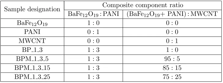
The reaction was terminated by filtering and repeatedly washing the as-obtained dark greenish-brown precipitate with ethanol and distilled water. The precipitate was oven-dried at 60◦C for 48 hours. The composite preparation was then completed, and the samples are ready for the characterization process. The samples tested in this work are divided into three main categories; single (BaFe12O19, PANI, and MWCNT), binary (BP 1 3) and ternary samples (BPM 1 3 5, BPM 1 3 15, and BPM 1 3 25). Table 1 lists the different composites prepared in this work. The designated sample name provides a rough idea on its composition. For example, for sample BPM 1 3 25, the ‘BPM’ notation implies that the sample is made up of BaFe12O19, PANI and MWCNT, while the ‘1 3 25’ signifies the ratio between the components. In this sample, the ratio of BaFe12O19 to PANI is set to 1 : 3. The combination of the two (BaFe12O19+PANI) was then treated as a single entity, and its amount is then compared with MWCNT by taking the ratio of BaFe12O19+PANI to MWCNT as 75 : 25.
Table 1. Prepared samples with different component ratios.
Sample designation Composite component ratio
BaFe12O19: PANI (BaFe12O19+ PANI) : MWCNT BaFe12O19 1 : 0 0 : 0
PANI 0 : 1 0 : 0
MWCNT 0 : 0 0 : 1
BP 1 3 1 : 3 1 : 0
BPM 1 3 5 1 : 3 95 : 5
BPM 1 3 15 1 : 3 85 : 15 BPM 1 3 25 1 : 3 75 : 25
2.2. Characterizations
Structural and morphological analysis were done through x-ray diffraction (XRD, Bruker A&S D8), Fourier-transform infrared spectroscopy (FTIR, Perkin Elmer), and Field-emission scanning electron microscope (FESEM, Supra 55VP ZeissVP-FESEM). A 4-point resistivity measurement system (Keithley 2400) was used to measure the electrical conductivity of the prepared composites. In order to perform electromagnetic testing on the composites, the powders were shaped into rectangular slabs with dimensions of 22.860 mm×10.16 mm×5 mm. The composite powders were mixed with 30% paraffin wax and were compacted in a rectangular mould by using a hydraulic press with an applied pressure of 5 kPa. The electromagnetic properties of the composites were evaluated by using a network analyser (Agilent Technologies E8362B PNA) at the X-band (8.2–12.4 GHz).
2.3. Shielding Effectiveness, SE
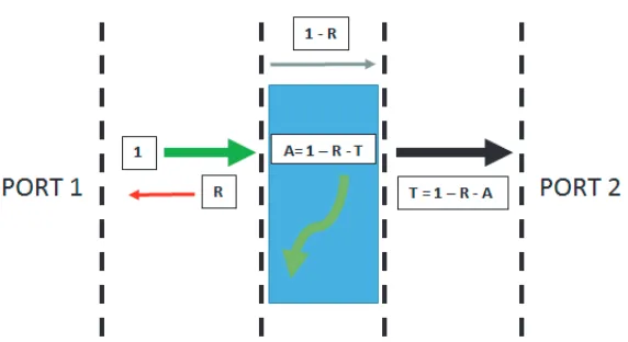
A wave, propagating from port 1 to port 2, when incident (1 = 100% power) on the surface of a medium with different impedances, would be split into three separate phases. Figure 1 details the wave propagation during the electromagnetic measurements.
A portion of the wave would be reflected (reflectance, R). Some would be absorbed within the medium of propagation (absorbance, A), and the remainder would transmit through (transmittance,
T). Theses constants can be derived from the scattering parameters (S11,S21,S12,S22) through:
T = ET
EI
2 =|S12|2(=|S21|2) (2)
T = ER
EI
2=|S11|2(=|S22|2) (3)
Figure 1. Wave propagation during network analyzer measurement.
The relative intensity of the electromagnetic wave propagating inside the medium after the reflection is given as (1−R). Therefore, the effective absorbance (Aeff), with respect to the intensity of the wave
within the material can be expressed as:
Aeff =
(1−R−T)
1−R (5)
By expressing the terms in dB, the values ofSEA and SER can be obtained as:
SEA = 10 log(1−Aeff) = 10 log
T
(1−R)
(6)
SER = 10 log(1−R) (7)
As the effect of the multiple reflections, SEM, is negligible when SEA ≥ 10 dB, the shielding performance depends only on the magnitude of shielding effectiveness through absorbance, SEA and reflection,SER.
3. RESULTS & DISCUSSIONS
3.1. Structural and Morphological Characterization
Figure 2 illustrates the XRD patterns of BaFe12O19, PANI, MWCNT, BP 1 3 and BPM 1 3 15. As both PANI and MWCNT are non-crystalline materials, the diffraction pattern of the composite mirrors that of BaFe12O19. The BaFe12O19 peaks match perfectly with the standard diffraction pattern, ICSD 98-004-7018. Despite the prominent “hump” representing the semi-amorphous structure seen in the diffraction pattern of pure MWCNT, the same pattern was not observed in any of the composite samples. This can be attributed to its small amount within the composition and also to the overlapping with the amorphous hump of PANI at 2θ= 20–30◦.
Figure 2. X-ray diffraction patterns of prepared composites.
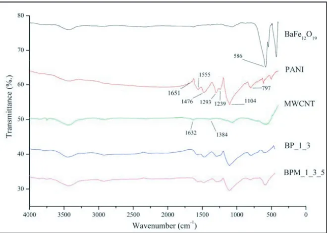
Figure 3. FTIR spectra of prepared composites.
the peaks of BaFe12O19 in the composites (586 cm−1) is less intense than pure BaFe12O19 [14]. This is due to the effect of the coating of PANI on BaFe12O19 particle surfaces [15].
(a) (b)
(c) (d)
(e)
Figure 4. FESEM images of: (a) BaFe12O19, (b) PANI, (c) MWCNT, (d) BP 1 3, and (e) BPM 1 3 15.
MWCNT microstructures, it is interesting to note the stark difference in the particles of PANI, between when it was synthesized on its own and when it is polymerized together with the particles of BaFe12O19 and/or MWCNT. As observed in Figure 4(b), on its own, aniline has the tendency to polymerize into tubular structures [16]. The presence of foreign particles during the polymerization process would result in the aniline to polymerize on the particle surfaces, giving it a ‘coating effect’ which would facilitate the interconnectivity between particles. This is significantly important in creating a minimum loading level for MWCNT to form a continuous network of conducting particles, otherwise known as the electrical percolation threshold [17].
Figure 5. Electrical conductivity of composite samples.
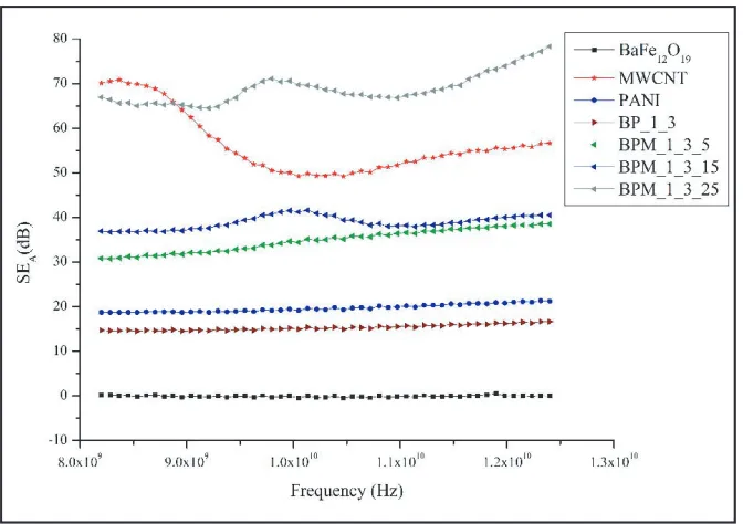
Figure 6. SEAcomparison between prepared samples.
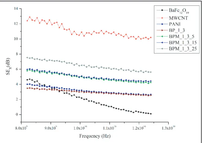
Figure 7. SERcomparison between prepared samples.
The comparison between the shielding effectivenesses of measured samples in this research work is shown in Figures 6 and 7. When comparing among the 3 composite constituents (BaFe12O19, PANI, MWCNT), BaFe12O19 shows the poorest shielding performance with theSEA values fluctuating above the 0 dB mark. A possible reason for this is the mismatch between the resonance frequencies for the optimum permeability values with the frequency range measured in this work. At microwave frequencies, the electromagnetic properties of magnetic materials is heavily reliant on its complex magnetic permeability, μr (μr = μ −jμ). This constant determines the magnetic loss mechanism
which in turn, affects the shielding properties greatly. In a study measuring the complex permeability of barium ferrite fibers, it was found that the natural resonance frequency for BaFe12O19 lies around 43.5 GHz [19]. However, it is possible to manipulate the material thickness and also pair it with different dielectric/conductive components to shift the resonance frequency to a lower frequency. The values of
SEAand SER exhibited by BaFe12O19 in this work imply that it is almost transparent to the incident
electromagnetic energy. Thus, it can be inferred that the thickness and association with dielectric components used in this study are not an optimum combination for the ferrite to perform well at frequencies 8.2–12.4 GHz. This requires further study on the optimization of BaFe12O19which is beyond the scope of this work. Pure MWCNT outperforms almost all of the measured samples in term of its
SEA and SER values. The highest SEA for this material was observed at the frequency of 8.36 GHz with the value of 70.8 dB, while for the rest of the frequency band, more than 50 dB of SEA was observed. This accounts for more than 99.99% of the wave energy propagating within the MWCNT solid sample being absorbed. This is not surprising considering the exceptionally high conductivity as compared to the other samples leading to enhanced dielectric losses. The SEA values of PANI fall in
between with values reaching 20 dB at frequencies between 10.8 and 12.4 GHz. The same phenomena were observed from the measuredSERvalues of the materials. However, it is important to note that the SER for BaFe12O19 was slightly better than that of PANI between 8.24 and 8.78 GHz albeit dropping
steadily as the frequency increases. This suggests that BaFe12O19, by itself, might be able to reflect electromagnetic waves better at lower frequencies.
The combination of BaFe12O19 and PANI results in itsSEAto fall slightly below PANI. Minimum
values of 14 dB (SEA) and 3 dB (SER) were observed throughout the X-band which translates to about
to reach minimum values of 30 dB (99.90% attenuation) and 5 dB (68.38% attenuation), respectively. Further 10 wt% increase in MWCNT increases the shielding further. Finally, at 25 wt% MWCNT, the
SEA value of BPM 1 3 25 far exceeds all of the other samples, to the point that it is even able to
outperform the shielding performance of MWCNT.
The composite samples have shown promising electromagnetic shielding properties where all composite samples were able to exhibit combined losses, both SEA and SER, of more than 20 dB
(99.00% attenuation). This was mainly attributed to the highly conductive nature of the composites. With respect to the classical electromagnetic theory, the shielding effectiveness due to absorption can be postulated through [20]:
SEA= 20
d δ
loge= 20d
ωμ
rσac
2
1/2
loge (8)
where d, δ, ω, μr, and σac are the shield thickness, skin depth, angular frequency, complex magnetic
permeability, and frequency dependent conductivity (σac =ωεoε), respectively. Equation (8) provides
an insight to the intrinsic parameters that can be tailored to achieve optimum shielding performance through absorption. Aside from the electromagnetic parameters, μ and ε, electrical conductivity plays a prominent role in determining the shielding performance of a medium. The increased conductivity would give rise to conductance losses, among others. This is reflected in the form of the conductance loss tangent, tgδc [8]:
tgδc = 1.8×10¹⁰ σ
f εr (9)
whereσ,f, andεr are the electrical conductivity, frequency and complex permittivity, respectively. The
combined effect from PANI and MWCNT leads to the enhancement of this dielectric loss mechanism. This was exemplified in sample BPM 1 3 25 surpassing theSEAof MWCNT despite the higher value of electrical conductivity shown by MWCNT. Generally, a higher conductivity results in a higher shielding performance. However, it is also important to note that the impedance of materials with very high conductivity tends to be low. This will pose a problem if higher absorption performance is desired as the behavior of the conductive material approaches that of the metallic sheets where most of the wave will be reflected instead of being absorbed [8]. This suggests the existence of a threshold for the MWCNT wt% loading in composite materials for optimum shielding performance. The high values of SEA and
SER for composite BPM 1 3 25 show potential in utilizing the material in practical applications.
4. CONCLUSIONS
BaFe12O19-PANI-MWCNT composites were successfully developed. XRD, FTIR and FESEM confirm the successful formation of the composite through thein-situpolymerization process. The XRD pattern of the composite closely mirrors that of BaFe12O19. FTIR measurements revealed the presence of functional groups characteristic to each composite constituent. The micrographs taken using FESEM showed the random distribution of the particles within the composite matrix. The composites are highly conductive due to prominent amounts of PANI and MWCNT. This led to the enhanced shielding behavior shown by the composites. All composites measured in this research work were able to exhibit shielding values of more than 20 dB throughout the X-band with the highest SEA value shown by
sample BPM 1 3 25.
ACKNOWLEDGMENT
The authors would like to express their gratitude towards Universiti Teknologi Petronas (UTP) and Universiti Malaysia Perlis (UniMAP) for facilitating this research work by providing the facilities and support leading to its successful completion.
REFERENCES
2. Jani, R. K., M. K. Patra, L. Saini, A. Shukla, C. P. Singh, and S. R. Vadera, “Tuning of microwave absorption properties and Electromagnetic Interference (EMI) shielding effectiveness of nanosize conducting black-silicone rubber composites over 8–18 GHz,”Progress In Electromagnetics Research M, Vol. 58, 193–204, 2017.
3. Xing, D., L. Lu, W. Tang, Y. Xie, and Y. Tang, “An ultra-thin multilayer carbon fiber reinforced composite for absorption-dominated EMI shielding application,” Materials Letters, Vol. 207, 165– 168, 2017.
4. Tong, X. C., Advanced Materials and Design for Electromagnetic Interference Shielding, Taylor & Francis, 2008.
5. Li, L., K. Chen, H. Liu, G. Tong, H. Qian, and B. Hao, “Attractive microwave-absorbing properties of M-BaFe12O19ferrite,” Journal of Alloys and Compounds, Vol. 557, 11–17, 2013.
6. Pullar, R. C., “Hexagonal ferrites: A review of the synthesis, properties and applications of hexaferrite ceramics,” Progress in Materials Science, Vol. 57, 1191–1334, 2012.
7. Wang, Y., T. Li, L. Zhao, Z. Hu, and Y. Gu, “Research progress on nanostructured radar absorbing materials,” Energy and Power Engineering, Vol. 3, 580, 2011.
8. Huo, J., L. Wang, and H. Yu, “Polymeric nanocomposites for electromagnetic wave absorption,”
Journal of Materials Science, Vol. 44, 3917–3927, 2009.
9. Zahari, M. H., B. H. Guan, E. M. Cheng, M. F. Che Mansor, and K. C. Lee, “EMI shielding effectiveness of composites based on barium ferrite, PANI, and MWCNT,” Progress In Electromagnetics Research M, Vol. 52, 79–87, 2016.
10. Xu, G., H. Ma, M. Zhong, J. Zhou, Y. Yue, and Z. He, “Influence of pH on characteristics of BaFe12O19 powder prepared by sol-gel auto-combustion,” Journal of Magnetism and Magnetic Materials, Vol. 301, 383–388, 2006.
11. Liu, J., W. Zhang, C. Guo, and Y. Zeng, “Synthesis and magnetic properties of quasi-single domain M-type barium hexaferrite powders via sol-gel auto-combustion: Effects of pH and the ratio of citric acid to metal ions (CA/M),” Journal of Alloys and Compounds, Vol. 479, 863–869, 2009.
12. Quillard, S., G. Louarn, S. Lefrant, and A. MacDiarmid, “Vibrational analysis of polyaniline: A comparative study of leucoemeraldine, emeraldine, and pernigraniline bases,” Physical Review B, Vol. 50, 12496, 1994.
13. Li, Y., Y. Huang, S. Qi, L. Niu, Y. Zhang, and Y. Wu, “Preparation, magnetic and electromagnetic properties of polyaniline/strontium ferrite/multiwalled carbon nanotubes composite,” Applied Surface Science, Vol. 258, 3659–3666, 2012.
14. Xu, P., X. Han, and M. Wang, “Synthesis and magnetic properties of BaFe12O19 hexaferrite nanoparticles by a reverse microemulsion technique,” The Journal of Physical Chemistry C, Vol. 111, 5866–5870, 2007.
15. Li, G., S. Yan, E. Zhou, and Y. Chen, “Preparation of magnetic and conductive NiZn ferrite-polyaniline nanocomposites with core-shell structure,” Colloids and Surfaces A: Physicochemical and Engineering Aspects, Vol. 276, 40–44, 2006.
16. Zhang, L. and M. Wan, “Synthesis and characterization of self-assembled polyaniline nanotubes doped with D-10-camphorsulfonic acid,”Nanotechnology, Vol. 13, 750, 2002.
17. Sandler, J., J. Kirk, I. Kinloch, M. Shaffer, and A. Windle, “Ultra-low electrical percolation threshold in carbon-nanotube-epoxy composites,” Polymer, Vol. 44, 5893–5899, 2003.
18. Konyushenko, E. N., J. Stejskal, M. Trchov´a, J. Hradil, J. Kov´aˇrov´a, J. Prokeˇs, M. Cieslar, J.-Y. Hwang, K.-H. Chen, and I. Sapurina, “Multi-wall carbon nanotubes coated with polyaniline,”
Polymer, Vol. 47, 5715–5723, 2006.
19. Pullar, R., S. Appleton, and A. Bhattacharya, “The manufacture, characterisation and microwave properties of aligned M ferrite fibres,” Journal of Magnetism and Magnetic Materials, Vol. 186, 326–332, 1998.