Analysis of Delamination Parameters in
Hybrid Composites Using Taguchi Method
Kendole Sharath Raghav1, Dr. G. Sankaraiah2, Dr. H. Raghavendra Rao3
P.G. Student, Department of Mechanical Engineering, GPR Engineering College, Kurnool, Andhra Pradesh, India1
Professor, Department of Mechanical Engineering, GPR Engineering College, Kurnool, Andhra Pradesh, India2
Associate Professor, Department of Mechanical Engineering, GPR Engineering College, Kurnool, Andhra Pradesh, India3
ABSTRACT: Composite Materials gaining momentum rapidly in its usage and in various practical applications hence
their fabrication and machining hold greater importance. Hybrid composites are formed by reinforcing two or more materials of varying properties. Composite is fabricated by using Natural fibre extracted from Acacia Nilotica (Egyptian Thorn) with combination of Glass fibre with various combinations. Wide application of composite necessisate the joining of two plates of composite, for making such joint drilling is required. Drilling being the most important processes in hole making operations, Delamination of the composite is the vital problem arising during any drilling operation of composite material. It not only causes damage but also causes long-term performance deterioration. Taguchi approach can be used for evaluating delamination factors during drilling of composite to determine the optimal cutting parameters for less damage of composite material. This paper makes an attempt to find the Tensile and Flexural Strengths of the various combinations of hybrid composites and Minitab software is used to apply Taguchi method for understanding delamination parameters and their significance.
1. INTRODUCTION
The use of Glass Fibre composite in Applications such as Aircraft, Ship Building, and Automotive has increased considerably in recent years due to significant properties that they exhibit [1]. Being corrosive resistant, possessing high strength and low thermal conductivity in addition to this they have light weight construction. There are various methods of fabrication of a composite material and the most commonly used method of fabrication is Hand Lay-up process. This method is used for the manufacture of Fibre- Reinforced, thermoset plastics and is used in the production of moulds. Firstly the fibres are weighed according to the weight ratio of the composite and are laid into the mould and then it is saturated using the Resin. Generally Hardener is used so as to set the complete fibre and resin at a faster rate. Tensile Strength or Ultimate Tensile Strength is the maximum capability of the material to withstand the loads tending to elongate. Tensile strength resists being pulled apart or tension. UTM (Universal Testing Machine) is used to find out the Tensile Strength of the Sample. A sample with fixed cross- sectional area in the form of dumbbell shape is cut and is fixed between the jaws of an UTM machine and it is pulled apart.
Flexural Test gives the stress that the material takes just before when it yields (just before when deformation of material becomes plastic). This is also called as Bend Strength of the material. The same UTM machine is used so as to find out the Flexural strength of the composite with various combinations of Natural fibre and Glass fibre in the composite.
Delamination is the most common and serious problem accompanying the drilling of a Composite Material [2]. This doesn’t only reduce the structural integrity of the composite but also results in poor assembly tolerance and has long-term performance deterioration. Composites are neither Isotropic nor Homogeneous, drilling raises specific problems such as Interlaminar cracking and Fibre pull-out [3]. They not only reduce the Reliability but also reduces Load-carrying capacity [4].
Figure 1. Hand Lay-up Process
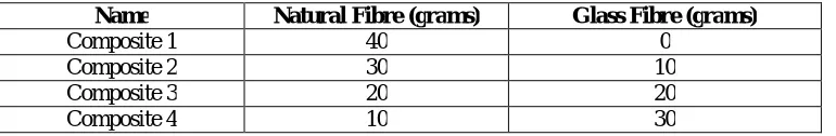
Table 1 represents various combinations of fibre in the composites fabricated. The total fibre content remains the same as 40 grams whereas the individual constituents of the composite changes as shown in the table below.
Drilling operation is then carried out on the composite at various Spindle speeds with varying diameters. The drill used is the HSS drill bit for the entire process of hole making.
II. FABRICATION OF COMPOSITE MATERIALS WITH VARIOUS COMBINATIONS OF FIBRES
Hand lay-up process is used so as to prepare composite materials and further they are cut according to the required shapes depending on the type of test performed. Every composite Fabricated consists an fixed amount of 40 grams of fibre where this total fibre composition varies and is distributed between Natural fibre (Acacia Nilotica) and Glass Fibre. The table below specifies the composites and their Fibre compositions.
Table 1. Combination of Fibres
Name Natural Fibre (grams) Glass Fibre (grams)
Composite 1 40 0
Composite 2 30 10
Composite 3 20 20
Composite 4 10 30
The table above represents various combinations of fibre in the composite. The total fibre content remains the same as 40 grams whereas the individual constituents of the Fibre changes as shown in above table. Step-wise procedure of hand-layup process in explained below.
1. Firstly a mould is taken and it is polished with wax such that Resin mixture doesn’t stick to the mould. 2. Thenfibres are weighed and are placed inside the mould and resin and Hardner mixture is poured on to it such that the entire fibre gets saturated.
Figure 2: Hand Lay-up Process of fabricating composites
3. Once fibres are set in the mould then a roller is taken and rolled over the fibres such that all fibres are equally coated with resin.
4. Then a glass plate is taken and placed over the mould and a weight is kept over it and is left undisturbed until it is set.
Figure 3. Fabricated Hybrid composite Material
The above figure is of the fabricated composite which is of 20-20 composition (i.e.;20 grams of Natural Fibre and 20 grams of Glass fibre).
III. TENSILE AND FLEXURAL TESTING OF THE COMPOSITE MATERIAL
(a) TENSILE TESTING:
Firstly composite material is cut into a standard Tensile testing specimen i.e.; as a Dumbbell shape with required dimensionsas shown in figure and a UTM machine is used so as to find tensile strength of the composite.
The figure below shown is the standard specimen according to which the tensile testing specimens are cut.
Figure 4.Tensile Testing Specimen
Tension is added at two ends of the specimen until the specimen fails. All the four composites i.e.; with different fibre combinations of the fibres are tested and the values are recorded.
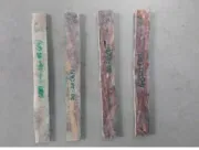
Figure 5. Tensile testing samples
The figure 5 above shown is the four different specimens with different combinations of the fibres. The first specimen is the composite with 30-10 composition second being 20-20 composition. The third has the composition of 10-30 and fourth is the composite with 40-10 composition (only Natural Fibre).
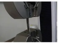
The specimens cut were tested for their Tensile strengths with the help of UTM (Universal Testing Machine). Figure 6 shows an UTM machine which holds both the ends of the Dumbbell shaped specimen and is Tension is added on to the specimen and until the specimen fails.
The following table shows the Maximum load taken by the specimen, tensile stress generated during failure of the specimen, Young’s Modulus and Tensile strain at the breakage. The table illustrates the properties of all the composites with different fibre combinations.
Table 2. Tensile strengths of the specimen
Specimen Maximum
Load(N)
Load at Break (N)
Tensile stress and Maximum Load(MPa)
Young’s Modulus(MPa)
Tensile Strain at
Break
Composite1 (40-0)
757.15 757.15 25.24 4561.10 0.00733
Composite2 (30-10)
800.78 800.78 26.69 3965.04 0.00833
Composite3 (20-20)
928.04 770.90 30.93 3628.06 0.01483
Composite4 (30-10)
2045.86 2026.61 34.10 2231.72 0.02317
From the above table we could draw a conclusion that as the amount of Glass fibre content increses in the composite, the strength of the composite increases considerably and the Tensile strain also increases. Maximum load is taken by the Composite (30-10) i.e.; with 30 grams of Glass fibre and 10 grams of Natural fibre(Acacia Nilotica). A maximum load of 2045.86 N is experienced and the Break load being 2026.61 N.
(b) FLEXURAL TESTING:
Flexural test gives the strength of the composite just before the material yeilds (when the deformation starts to become plastic) and Composite material is cut into a Standard Rectangular shape and the dimensions are shown in figure below. A load is added on the center of the specimen with two supports at both ends.
Figure 7. Flexural Testing Specimen
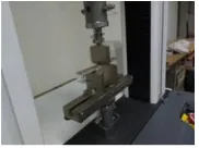
The figure below shows the way loading of speimen into the UTM and the Flexural testing is done. The specimen is supported at two ends and a load is added at its centre till the specimen fails. This is also called as bend test.
The figure below are the four specimens which are cut into rectangular shape with different compositions of fibres in them and they have a standard size as shown in the above figure. The first is 30-10 composite, second being 20-20 composite, third is a 10-30 composite and fourth is a 40-0 composite (complete Natural Fibre).
Figure 9. Flexural Testing Specimens
Table 3 below shows the flexural strengths of the different compositions of the composites. Each specimen is loaded sequentially and testing is done.
Table 3. Flexural Strength of the Composites
Specimen Maximum Load(KN) Maximum Stress (MPa) Flex Modulus(MPa)
Composite1 (40-0)
0.15 84.70 12400.15
Composite2 (30-10)
0.25 136.75 13300.95
Composite3 (20-20)
0.52 288.26 14913.55
Composite (10-30)
0.12 6.84 11859.83
From the table above we can say that the composite with 20grams of Glass Fibre and 20 grams of Natural Fibre (Acacia Nilotica ) has more Flexural Strength with a maximum load of 0.52KN, maximum stress being 288.26MPa and Flexural Modulus being 11859.83MPa.
IV. DELAMINATION AND TAGUCHI OPTIMIZATION METHOD OF THE HYBRID COMPOSITE
TAGUCHI OPTIMIZATION PROCEDURE:
Now the Hybrid Composite is drilled using a HSS Drill bit with three different diameters and the the Spindle is run at three different speeds [6,9]. The diameters of Drill bits used here are with diameters 5mm,6mm and 8mm.The three different speeds are being 100rpm ,200rpm and 300rpm Speeds of the bits. For a diameter of drill bit it would be run at three different speeds and the Orthogonal Array of this particualar thing is given below.With all the above runs, drilling of holes on the composite is done and the delamination is observed. Delamination Factor (Fd) is observed in
each and every run of the i.e.; for every run a hole is drilled and delaminated diameter is measured and found. Delamination factor is quantified by using the following relation. Taguchi’s L9 Orthogonal Array is used.
Delamination Factor (Fd) =
Table 4 below shows the L9 Orthogonal Array which is actually a Design of Experiments and it shows all the possible combinations of the runs.
Table 4. Orthogonal Array of the Runs
Run Order
Drill Diameter (DD)
Spindle Speed (SS)
1 5 100
2 5 200
3 5 300
4 6 100
5 6 200
6 6 300
7 8 100
8 8 200
9 8 300
Figure 10 below is the Actual drilled hole with the drill bit of 8mm diameter and with 300 rpm of Spindle Speed. And the delamination is clearly observed surrounding the drilled hole.
Figure 10. Actual Drilled hole
Figure11shows detailed scheme of delamination and shows the diameter of actual drilled hole and the diameter of the delaminated area. Diameters of the actual hole and delaminated surface could be easily distinguished.
Figure 11. Scheme of Delamination
V. RESULTS AND DISCUSSION
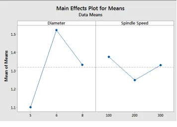
ANOVA is a statistics based decision-making tool for predicting any differences in the average performance of groups. It assists in formally testing the significance of all main factors and their interactions by relating the mean square against an estimate of the experimental errors at specific confidence levels.
Figure 12. Mean effect plot of Delamination
The Analysis of Variance (ANOVA) was used to study the effect of drilling parameters. Tables 6 and 7 provides ANOVA results for delamination factor in drilling with Drill bit diameter and spindle speed respectively of Hybrid composite. Factors which has p value less than 0.05 are considered as significant
Table 6. Anova for delamination factor with Diameter
Source DF Adj SS Adj MS F-value P-value
Diameter 2 0.26627 0.133134 15.11 0.005
Error 6 0.05286 0.008810
Total 8 0.31913
Table 7. Anova for delamination factor with Spindle speed
Source DF Adj SS Adj MS F-value P-value
Spindle Speed 2 0.02490 0.01245 0.25 0.784
Error 6 0.29423 0.04904
Total 8 0.31913
VI. CONCLUSION
REFERENCES
[1] Chen, W. C., “Some experimental investigations in the drilling of carbon fibrereinforced plastic (CFRP) composite Laminates”, Int. J. Machine Tools and Manufacture, Vol.37, pp. 1097-1108; 1997.
[2]Mahapatra SS, Patnaik; “A Study on mechanical and erosion wear behaviour of hybrid composites using Taguchi Experimental Design” MeterMater Des; Vol.30, pp. 2791–801; 2009.
[3]Hocheng, H., Tsao, C.C., “Comprehensive analysis of delamination in drilling of composite material with various Drill bits”J. Mat. Proc.Techvol.140, pp. 335-339; 2003.
[4] Jung, J. P., Kim, G. W., Lee, K. Y., “Critical thrust force at delamination propagation during drilling of angle-ply Laminates” , Composite Structures, Vol. 68, pp. 391- 397; 2005.
[5]Lachaud, F., Piquet, R., Collombet, F., Surcin, L., “Drilling of composite structures” Composite structures, Vol. 2,pp. 511-516; 2001.
[6] Hocheng, H., Tsao, .C., “Comprehensive analysis of delamination in drilling of composite materials with various Drill bits”,”, J. Mat. Proc.TechnVol.140, pp.335-339; 2003.
[7] Jung, J. P., Kim, G. W., Lee, K. Y., “Critical thrust force at delamination propagation during drilling of angle-ply laminates”, Composite Structures, Vol.68, pp. 391- 397; 2005.
[8] H. Hocheng, C.K.H. Dharan, “Delamination occuredduring drilling in composite laminates”, Transactions of the ASME, Journal of Engineering Journal of the Engineering Industry”, Vol.112 ,pp.236–239;1990.
[9] Kilickap, E.,” Optimization of cutting parameters on delamination based on Taguchi method during drilling of GFRP composite”. Expert systems With applications , Vol. 37, pp.6116-6122,2010.
[10] Veniali,F., A. Di Ilio, and V.Tagliaferri, "An experimental Study of the Drilling Aramid Composites”. Journal of Energy Resources TechniqueVol.117, pp. 271-278, 1995.
[11]Hocheng,H and C.Tsao,“Analysis of delamination in drilling composite materials using core drill". Australian Journal of Mechanical Engineering Vol.1, pp. 49, 2003.