Modelling and Analysis of Electric Powertrain
using Open Modelica and ANSYS Workbench
Shamueel Mujtaba1, Rishi V Orpe2, Jyothsna K Moorthy3
U.G Students, Department of Mechanical Engineering, PES University, Bangalore, India 1, 2
Assistant Professor, Department of Mechanical Engineering, PES University, Bangalore, India3
ABSTRACT: The demand for vehicles with Alternative Propulsion technologies has increased in the recent past due to the rapid decline of fossil fuels caches, and an increased awareness of the impact of emissions on our environment. Electric vehicles (EV’s) however, have lower acceptance than conventional gasoline engine vehicles due to factors like initial cost, range, and life. The implementation of a gear box in low cost, BLDC motor driven EV’s will result in a better performance by balancing the torque and speed requirements during different situations. The gearing was chosen based on the Traction diagram of the given Motor-Vehicle configuration generated in MATLAB. Further, a Mathematical model of the complete electric Powertrain was simulated in the OpenModelica software to generate the required input torque characteristics of the motor for the chosen gearing, so as to compare it with actual motor characteristics. The gears were analyzed in the Static structural condition of the ANSYS workbench to check for the equivalent stresses, deformation and contact frictional stresses. The simulations and analysis mentioned were carried out for an Open-wheel EV, and the design proven safe for the chosen operating conditions, before moving on to the detailed designs.
KEYWORDS:Electric vehicles (EV’s), Traction diagram, BLDC, OpenModelica, ANSYS Workbench, Open-wheel.
I. INTRODUCTION
Powertrain in any vehicle is needed to enable the vehicle to move from rest. It consists of power plant, clutch, gearbox, final drive, axle and wheels. It plays an important role in terms of acceleration and speed of the vehicle. The design of Powertrain has to be made with due consideration of the operational constraints of the complete system. The Commuter and Commercial Vehicle segments of the automotive industry are the major constituents of the ‘mass-market’. The success of a product in these segments (in developing markets) depends on the perceived value of the product, the perception being based majorly on its visual and tangible features. This makes it imperative for a manufacturer to allocate lesser (and cheaper) resources towards the development of the Powertrain of the vehicle, when compared to its other subsystems. This kind of allocation impacts the Hybrids and pure Electrics more so, where the cost of the Battery and the Motor are a significant part of its overall price. Thus their sale is impeded when compared to the more established ICE vehicles of a similar class. Considering the prevailing scenario, it becomes all the more necessary to develop mechanical systems that can extract the most out of lower powered Electric motors at all their operational frequencies, thus providing a suitable compromise between the acceleration and top speed characteristics of the vehicle. Open-wheeled cars are lending themselves to be the ideal test rigs for any desired experimental layouts of the Powertrain due to their ‘bare-bones’ nature and the absence of design constraints normally applicable to Passenger vehicles. This also makes it easier to identify and locate the anomalies, if any, in the overall assembly of the Powertrain without the risk of admittance of noise from nearby subsystems. Hence a similar class of vehicle is considered in the development of our analysis.
II. RELATEDWORK
There has been immense research carried out in the field of power transmission, and hence a large amount of literature on gear modelling and analysis has been published. The report by Staffan Enocksson [16] introduced techniques of modelling a gearbox in Simscape, which were used to implement the same on an open-source platform (OpenModelica). The gear stress and deformation was found by meshing and analysis by Ghosh .et al. [13] for a single tooth of the gear in Static Structural condition, for different vehicles at specified torques. The maximum contact stress was determined using Hertz equation and Finite Element Method by Mushiri .et al. [14].
III.PROPOSEDMETHODOLOGY
For the vehicle Powertrain to be designed, we first come up with its realistic target performance characteristics.
i. Targets:-
+0.6g longitudinal acceleration
70 kmph+ top speed
100 Gradability
Minimal-to-zero driver input in Powertrain functions
ii. Assumptions:-
Motor Brushless DC, LBC 125-8D series, 72V, 6kW
Dimensions (l x b x h) = 342.8x140x140 mm
Rated torque = 18 Nm
Peak torque = 54 Nm
Rated speed = 3000 rpm
Shaft diameter = 24 mm
iii. Vehicle
specifications:-iv. Preliminary design:-
1. Considering the above goals, we first find the maximum torque that the wheels can sustain (without sliding) during acceleration.
X = h/wb = 0.2293
Dynamic axle weights:
Mdyn_f = ([{1-0.6)} - (X*a)]*M = 78.73 kg (a=0.6 g units)
Mdyn_r = M – Mdyn_f = 222.27 kg
Traction limit of tyres = (μs * (Mdyn_r) * g) * (dr/2) = 404.48 Nm
The upper limit for the Torque at wheels (both combined) is now set to 450Nm to account for losses in the Powertrain. Each wheel therefore receives 225Nm (50%) at any given time for an open-differential.
Mass of car, M 300kg(with driver, worst case)
Coefficient of friction (sliding) between road and tire, μs
0.7
Tire rolling diameter, dr 530mm
Centre of gravity height, h 360mm
2. Gear reduction for achieving the torque is determined. The maximum speed achievable for this reduction is found.
Gear Ratio = 450/54 = 8.33
Wheel rpm = 3000/8.33 = 360.14rpm
Road speed = (PI*dr*N/60)*3.66 = 36.6kmph
3. The top speed is insufficient with regards to the goals set above and hence, we need another gear which pushes the speed up to the desired value.
On back calculating, Wheel rpm at 70 kmph = 19.44*60/ (PI*dr) = 700rpm
Gear ratio = 3000/700 = 4.28
4. The net resistance (Torque-Speed) plot is drawn in MATLAB for speeds up to 80kmph in terms of wheel rotations per minute. On the same graph, a general BLDC motor characteristic curve is plotted. This curve incorporates the two gear steps as determined above. The point where the resistance and motor curves intersect gives the top speed, while the area between the two is used to determine the Drawbar pull, and subsequently, the acceleration achievable at every speed.
Fig (1.1) Fig (1.2)
Traction diagram Powertrain layout
5. The overall gear ratios are finetuned (trial & error) using the graph in Fig (1.1), to maximize the net area under the curve as well as the top speed achievable. A shift speed at which the gear change takes place is also automatically fixed at the intersection of the two motor characteristic curve's step.
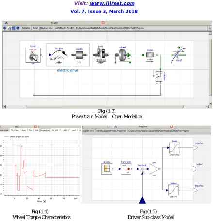
Fig (1.3)
Powertrain Model – Open Modelica
Fig (1.4) Fig (1.5)
Wheel Torque Characteristics Driver Sub-class Model
v. Final values:-
GEARBOX:
Gear # Gear Ratio Number of
teeth(Driven/Driver)
Diameter in mm (Driven/Driver)
1st Gear 2.900:1 87/30 174/60
2nd Gear 0.857:1 54/63 108/126
Shaft centre distance - 117mm
FINAL DRIVE/SPROCKET:
Sprocket speed reduction - 2.882:1
Sprocket Number of teeth Diameter (mm)
Driving 15 76.2
Driven 43 217.5
Fig (2.1) Fig (2.2)
CATIA model of Powertrain CATIA model of detailed Gearbox
A crude rendition of the Powertrain is pictured in Fig (2.1) with the detailed view of the 2-Speed sliding mesh Gearbox in Fig (2.2). The chain pitch and bushing were chosen in accordance with the standard load/rating tables from different manufacturers. Sprocket for the driven side is fabricated to meet the bolting dimensions of the open differential cage, while the differential is chosen from a front wheel drive TATA IRIS since its power and torque ratings were closest to our application.
Overall Gear ratios Top speed Average
acceleration
Gradability Shift speed
1st 8.358 68kmph 0.5g 34.170 36kmph
IV.NON-LINEAR ANALYSIS IN ANSYS WORKBENCH
i. Methodology
The Non-linear analysis was carried out on two sets of gear pairs i.e. 87/30 and 54/63 in ANSYS R18.2. The gears were in mesh with their respective pairs, with frictional co-efficient of 0.2 between the contacting faces. The element mesh was fine with Proximity and Curvature conditions chosen. The driver gears of 30 teeth and 63 teeth were subjected to fixed support, while the other gears were on frictionless support. The remote points were created and a moment of 54Nm was applied at the respective driver gears for both the ratios. The non-linear solution was obtained to check for Equivalent stresses, Total Deformation and Contact Frictional stresses.
ii. Discussion and results
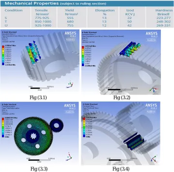
Alloy Steel (EN-19) is used in the manufacturing of the Gears blanks and Shafts. The Gears also undergo Case Hardening and the subsequent Heat treatment for stress release, after they’ve been hobbed for generating the Involute-profiled teeth. Wire cutting is employed in machining the splines on the shaft required for the Sliding-mesh mechanism.
Fig (3.1) Fig (3.2)
Fig (3.3) Fig (3.4)
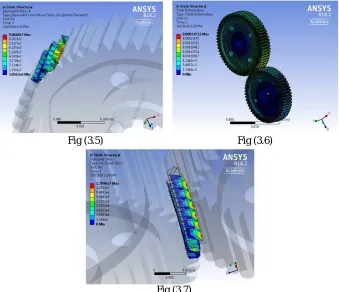
Fig (3.5) Fig (3.6)
Fig (3.7)
In the Fig (3.5), the Elemental equivalent stresses were obtained by hiding one of the gears from the pair. The stress obtained was 90.68MPa which is much less than the material’s Yield strength of 555MPa. In Fig (3.6) the total deformation was obtained as 0.247 mm and in Fig (3.7), the Frictional stress at the contact is 12.096MPa.
A few engineering drawings and the final prototype are shown below:
Fig (4.1) Fig (4.2) Fig (4.3)
V.CONCLUSION
A simplified approach has been devised to design and validate a Powertrain, and its subsystems using the given operational constraints. The mathematical model developed in OpenModelica serves as a base for future analysis involving a higher resolution of the details that go into modelling a real physical system. The gears were analysed in the Static Structural condition using FE software and were found to be safe for the given operating conditions. The deformation was minimal and the maximum stress was below the Yield stress of the material. The contact stresses due to friction were also considered and they were found to be below the Yielding limit due to Shear. Both sets of gears were designed with a Safety Factor of more than 2.5.
REFERENCES
[1] Bhandari, V. B. (2010). Design of Machine Elements. Tata McGraw-Hill Education. [2] Buckingham, E. (1988). Analytical Mechanics of Gears. Courier Corporation.
[3] C. B. Tsay, Z. H. (1988). Tooth Contact Analysis for Helical Gears with Pinion Circular Arc Teeth and Gear Involute Shaped Teeth. ASME . [4] Ceraolo, M. (2017). SMEHV. Retrieved from OMWEBbook: http://omwebbook.openmodelica.org/SMEHV
[5] Dimensions for Involute sided Splines. (1966). IS:3665 . Bureau of Indian Standard ( BIS) .
[6] Fritzson, P. (2010). Principles of Object-Oriented Modeling and Simulation with Modelica 2.1. John Wiley & Sons. [7] IS:3075 (Part 1). (1966). Specification for Circlips . Bureau of Indian Standards (BIS).
[8] Joseph Shigley, C. M. (2004). Standard Handbook of Machine Design. McGraw-Hill standard handbooks.
[9] Nakandakar, C. H. (n.d.). Influence of Gear Loads on Spline Couplings. Retrieved from powertransmission.com: https://www.powertransmission.com/issues/0214/spline-couplings.pdf
[10] Rao, S. S. (2017). The Finite Element Method in Engineering (6 ed.). Butterworth-Heinemann.
[11] Smith, J. O. (n.d.). Stresses Due to Tangential and Normal Loads on an Elastic Solid with. Journal of Applied Mechanics . [12] Stokes, A. (1992). Manual Gearbox Design. Butterworth-Heinemann.
[13] Sushovan Ghosh, R. G. (2016). Structural Analysis of Spur Gear Using Ansys Workbench 14.5. IJMET , 7 (6).
[14] Tawanda Mushiri, C. M. (2015). Analysis of a gear train using finite element modelling. International Conference on Operations Excellence and Service Engineering. Orlando.