Stabilisation of Cart Inverted Pendulum using
the Combination of PD and PID Control
Arya V A1, Ashni Elisa George2
M.Tech Scholar, Dept. of EEE, Mar Baselios College of Engineering and Technology, Nalanchira, Kerala, India1
Asst. Professor, Dept. of EEE, Mar Baselios College of Engineering and Technology, Nalanchira, Kerala, India2
ABSTRACT:Cart Inverted Pendulum (CIP) consists of an Inverted Pendulum (IP) mounted on top of a Cart that move in horizontal direction. Pendulum is a rod that show to and fro motion and settle at its stable equilibrium position. The objective is to stabilise the Pendulum at its upright position but a Pendulum at its inverted position is unstable and will fall down hence a control is necessary to stabilise the Pendulum at its inverted position. The control is provided to the Cart such a way that the movement of the Cart will stabilise the Pendulum. Here two separate controllers are used for controlling the Pendulum angle and the Cart position. PD controller is provided for the position control of Cart and PID controller is provided for the angle control of Pendulum. These two controllers are combined together and the total control action will stabilise the Pendulum at its upright position thereby moving the Cart in the linear direction. Simulation work is done on MATLAB/Simulink environment.
KEYWORDS:Cart Inverted Pendulum, PD controller, PID controller, Cart, Pendulum, Simulink.
I. INTRODUCTION
A plant is to be stabilised at a desired point due to the inherent non-linearity present in that plant as in the case of Launch Vehicles, balancing a stick in hand etc. IP models are used for studying these stabilization problems. The CIP system consists of a pendulum mounted on top of a linearly moving Cart [1]. The movement of the Cart is necessary to keep the pendulum stable at its inverted position. A proper control action is used for the Cart movement. The cart can move only in horizontal direction, while the Pendulum rotate in the x-y plane [2]. The Pendulum is to be stabilised at the vertical position by moving the Cart with a control. This is the main objective. PD controller is used for the control of position of the Cart and PID controller is used for the control of angle of the Pendulum. The combined control action is used to satisfy the objective [3].
The position of the Cart is controlled using a PD controller [4]. It has two parameters such as Proportional, Derivative gains denoted as , , respectively. This control increases the system stability because it has the ability to predict the future error of the system response. The effects of sudden change in the error signal are reduced by taking the derivative of the system output instead of error signal. The derivative is designed to be proportional to the change in output. This will prevent the sudden changes in the control output due to the sudden changes in the error signal. The angle of the pendulum is controlled using a PID controller [5]. It has three separate parameters such as Proportional, Integral and Derivative gains. This control is relatively simple. For in many process control tasks, it provides satisfactory performance. It helps in eliminating steady-state offsets through integral action and it can anticipate the future through derivative action. This control provides better steady state and transient responses. It has higher stability and has no steady state error and oscillations and can be used with higher order processes.
II. RELATED WORK
The Control of CIP system is done using coupled Sliding Mode Control (SMC). SMC law is designed such a way that with in a finite time the coupled sliding surface should be reached. The zero dynamics are generated as a second-order damped and forced nonlinear differential equation. The stability analysis helps in showing whether the zero dynamics is semi-globally or asymptotically stable over the upper half-plane and the whole plane except the horizon. Due to the semi-global stability of the zero dynamics aggressive swing up and stabilization control can be achieved by a single coupled SMC law [8]. The performance of the proposed method is demonstrated in simulation experiment for the swing-up and stabilization control of CIP system. Similarapproaches canbeemployedtoother types of under-actuated systems with two degrees of freedom.
III.MODELLINGOFCIP
An IP mounted on top of the Cart is given fig. 1. The Pendulum mass (m) is assumed to be concentrated at the Centre of Mass. The Pendulum rod has an uniformlength (L) and the length from the pivot point to the Centre of Gravity (l). The Pendulum angle( ) . Mass of the Cart (M) and the Cart position is represented as (x). The friction on CIP is neglected. The control force applied is (F). Only two dimensional problem is considered here [9].
Fig. 1: Free-body diagram of CIP
The nonlinear equations of motion are
= ( + ) ̈ − ̈ + ̇ (1)
( + ) ̈ = + ̈ (2)
After linearization by small angle approximation
̇ = 0 ; Cos = 1 ;Sin = (3)
sub in (6) & (7) ; we get
Fromthe above equations (6) and (7).
The transfer functions for Pendulum and Cart are obtained as
( )
( )=[[( )( )] ] [( ) ] (8)
( ) ( )=
[ ]
[[( )( )] ] [( ) ] (9)
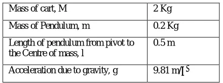
Table 1: Parameters for CIP
Mass of cart, M 2 Kg
Mass of Pendulum, m 0.2 Kg
Length of pendulum from pivot to the Centre of mass, l
0.5 m
Acceleration due to gravity, g 9.81 m/
The parameters chosen for the Plant is given in the Table: 1. The values are substituted in the transfer functions of Cart and Pendulum. For simplicity, a gain of 15 unit represent the DC motor used to convert control signal to control force.
( ) ( )=
.
(10)
( )
( )= .
. (11)
The transfer functions of Cart and Pendulum is provided in equations (10) an (11). Suitable control is designed for the Cart and the Pendulum separately and then the controls are combined and provided to the Cart and Pendulum subsystems [12].
IV.PROPOSEDCONTROLSTRUCTURE
Fig. 2: Block diagram for the Control set up
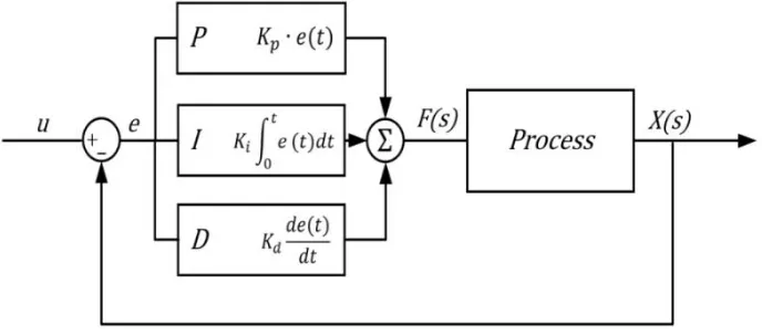
A) PID CONTROL
Proportional–Integral–Derivative (PID) control is relatively simple and provide satisfactory performance in many process control tasks. It has the ability to eliminate steady-state offsets through integral action and it can anticipate the future through derivative action. It has the advantages such as higher stability, zero steady state error, short rise time, zero oscillations and it can be used with higher order processes with more than single energy storage.
Fig. 3: Block diagram for PID Control
= ( )− (13)
= ( ) + (14)
where = | | and =∠
= | ( )|and =∠ ( )
, and are the proportional, integral and derivative gain. is velocity error constant
B) PD CONTROL
The aim of using P-D controller is to increase the stability of the system since it has an ability to predict the future error of the response. In order to avoid effects of the sudden change in the error signal, the derivative is taken from the output of the system instead of error signal. Therefore, D mode is designed to be proportional to the change of the output variable to prevent the sudden changes in the control output resulting from sudden changes in the error signal. The PD controller is designed by selecting a desired pole =− ± (1− ) by choosing desired specifications for damping ratio, natural frequency and steady state error.
= ( ) (15)
= ( ) (16)
where = | | and =∠
= | ( )|and =∠ ( )
and are the proportional and derivative gain.
V. EXPERIMENTALRESULTS
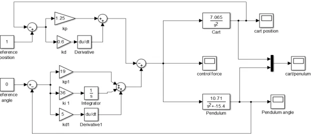
Thevalues of PID gains for the pendulum subsystem are designed as = 21, = 37, = 5.The values for PD gains for the Cart subsystem are designed as = 1.25, = 0.5. The Simulink model for CIP control is shown in fig.4. Cart position reference is chosen to be 1m and the Pendulum angle reference it is chosen to be 0 rad.
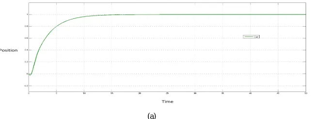
Fig. 5 shows the simulation results of the plant with the combination of PD and PID control. The Cart is provided with a reference position of 1m. The designed gain values of PD control is provided to the Cart transfer function. The Cart position tracking the reference position is shown in fig. 5(a).
(a)
The Pendulum is provided with a reference angle of 0 rad. The designed gain values of PID control is provided to the Pendulum transfer function. The variation of Pendulum angle with time is simulated. The fig. 5(b) shows the Pendulum angle tracking the reference angle 0 rad.
(b)
VI. CONCLUSION
Two separate controllers are used for Cart and Pendulum subsystems. The PD control has shown a good tracking for the reference position of Cart. PD control and conventional PID control was designed and simulated in MATLAB/Simulink environment. The Pendulum is stabilized at the inverted position by providingthe combination of PD and PID control for Cart position tracking and Pendulum angle respectively. The simulation results suggest that better response is obtained by combined control.
REFERENCES
1. Mohamed I. El-Hawwary, A. L. Elshafei, H. M. Emara and H. A. Abdel Fattah,“Adaptive Fuzzy Control of the Inverted Pendulum Problem”, IEEE Transactions on Control System Technology, vol. 9, no.6, pp. 1135-1144, Nov. 2012.
2. AhmetZeynel, HakanFatih, “Control of Nonlinear Dynamic Inverted Pendulum System Using Fuzzy Logic Based Control Methods”, IEEE Conference on Fuzzy Systems, pp. 2278-0181, Sept. 2014.
3. Gosh, T. R. Krishnan, B. Subudhi, “Robust Proportional-Integral-Derivative compensation of an Inverted-Cart Pendulum System”, IET Transactions on Control Theory and Applications, vol. 6, no. 8, pp. 1145-1152, 2012.
4. Mahadi Hassan, Md. MostafizurRahman and Subrata K. Aaditya, “Balancing of an Inverted Pendulum Using PD controller”, IEEE Conference on Control theory, pp. 150-120, Jan. 2012.
5. Sandeep D. Hanveeth, Yogesh V. Hote, “Design of PID controller for Inverted Pendulum using Stability Boundary Locus”, IEEE Conference on Control theory,pp. 380–387, 2014.
6. Suresh P Pingale, Sharath B Jadhav and Vivek P Khalane, “Design Of Fuzzy Model Reference Adaptive Controller For Inverted Pendulum”, IEEE Conference on Information processing,” pp. 790-794, Dec. 2015.
7. Rong-Jong Wai, Meng-An Kuo, and Jeng-Dao Lee, “ Cascade Direct Adaptive Fuzzy Control Design for a Nonlinear Two-Axis Inverted-Pendulum Servomechanism”, IEEE Transactions on Systems, Man, and Cybernetics, vol. 38, no. 2, pp.1277-1288, April 2008.
8. Moon-Su Park, DongkyoungChwa, "Swing-Up and Stabilization Control of Inverted-Pendulum Systems via Coupled Sliding-Mode Control Method", IEEE Transactions on Industrial Electronics, vo1.56, no. 9, pp.3541-3555, Sept. 2009.
9. NenadMuskinja , Boris Tovornik , “Swinging Up and Stabilization of a Real Inverted Pendulum”, IEEE Transactions on Industrial Electronics, vol. 53, no. 5, pp. 631-639, April 2006
10. kui-Kai Shyu, Ming-Ji Yang, Yen-Mo Chen and Yi-Fei Lin, “Model Reference Adaptive Control Design for a Shunt ActivePower-Filter System”, IEEE Transactions on Industrial Electronics, vo1.55, no. 3, pp. 97 - 105, Jan. 2008.
11. Chaio-Shiung Chen, Wen-Liang Chen, “Robust Adaptive Sliding Mode Control Using Fuzzy Modeling for an Inverted-Pendulum System”, IEEE Transactions on Industrial Electronics, vol. 45, no. 2, pp. 297-306, April 1998.