Novel Industrial Data Acquisition System
Using IOT
B.Jyothe Kritica1, Senthil Kumar A2, Raja S3, Sivaprasath K
II Year P.G. Student, ME Embedded System Technologies, Sri Shakthi Institute of Engineering and Technology, Coimbatore, Tamilnadu, India. 1
Assistant Professor, Dept. of ECE, Sri Shakthi Institute of Engineering and Technology, Coimbatore, TN, India. 2,3
ABSTRACT:Now a day Internet of Things is suddenly increasing technology. IOT is the network of physical object or
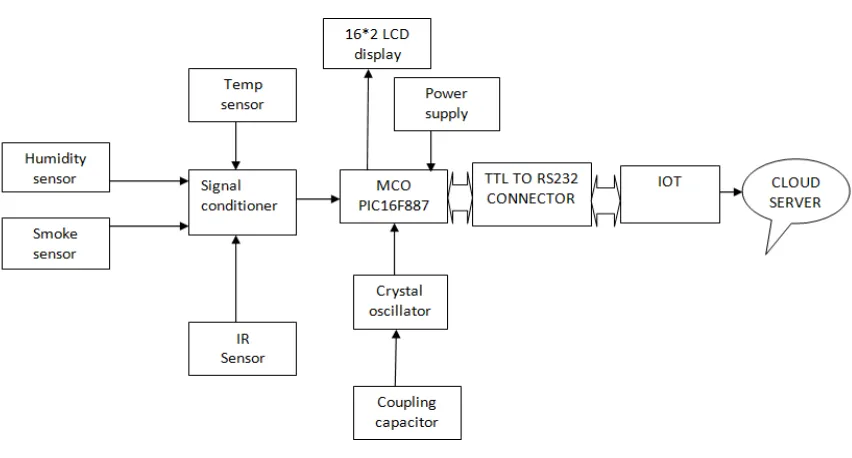
things embedded with software sensors, electronics and network connectivity. IOT is used to collect information and exchange data. In this paper, we are developing a system which will automatically monitor the industrial applications. IOT has given a powerful way to build industrial system by using wireless devices, and sensors. IOT concept is to monitor and control the industry. In phase I the hard ware was designed successfully using IOT. The input from sensor and data output can be displayed in the LCD (16*2).microcontroller (PIC16F887) which is used to collect data from sensors and displayed in LCD. The displayed data can be seen by server using IOT. The performances are verified experimentally using IOT. In Phase II the data from the server can be monitor through personal computer .The industrial data can be viewed through URL.
KEYWORDS:Internet of Things, industrial applications, microcontroller, health care parameters, personal computer.
I. INTRODUCTION
II. RELATEDWORK
Gas turbines become a work horse throughout the world for various industrial applications. Their reliability, operating efficiency and cost can be optimized with predictive maintenance. Proper calibration of the turbine's control system is critical to its safe operation, reliability, and minimization of operational costs. A faulty control system can quickly destroy expensive components of the gas turbine during just one improper start up cycle. In the early 1980's, as the personal computer (Pc) became available, PC based data acquisition systems migrated out of the laboratory and in to industry. The cost of installing a data acquisition system on a gas turbine control system was high. It was uneconomical to place such a system on a gas turbine that was used only occasionally, such as an electric utility's peaked unit. A data acquisition system that could be moved from unit to unit could been economical method of envying a control system's calibration and monitoring a gas turbine's performance. Such a portable data acquisition and analysis system was developed in 1985 by the author and another individual employed at Golden Valley Electric Association, a rural electric cooperative in interior Alaska. Its development was begun as a hobby, something which was fun as well as useful. It eliminates costly and time consuming cable lying for new and retrofitting of existing project. This wireless conduit is an interference free link between remote devices and control room, it is ideal for a noisy industrial environment. The subject of this paper deals with monitoring, controlling, and acquiring data continuously from an industrial process using this wireless conduit. The authors plan to demonstrate the interfacing of an industrial process, transducers, and final control elements to a remotely located Computer controlled data acquisition system. The monitoring and controlling of remote process via a reliable link without sacrificing the data integrity and loss of ability to analyse the acquired data will .be discussed. We are proposing to show how this wireless conduit is a two-way monitoring and controlling solutions for a variety of industrial application in heavy interference environment where other radios fail to perform. Data Acquisition Systems have an important role in the market today as many leading companies like National Instruments have specialized in the making of such devices. This paper deals with building a low cost system with components easily obtained in the market. It's more like a walk through tutorial of how to construct an advanced system with these components. The DAQ system itself is made up of a central processor unit connected to GUIs, memories, sensors and other I/O devices.
The Concepts of Internet of Things (IoT) are applied to a number of applications ranging from home automation to industrial IoT, Where connecting physical things, from anywhere through a network. Let them take an active part in the Internet, exchanging information about themselves and their surroundings. This will give immediate access to information about the physical world and the objects in it leading to innovative services and increase in efficiency and productivity. The proposal of system is to develop an IoT based Interactive Industrial Home wireless system, Energy management system and embedded data acquisition system to display on web page using GPRS, SMS & E-mail alert. This device is essential for sensor data collection and controlling of the industrial Home Wireless Sensor Networks (WSN) in the Internet of Things (IoT) environment. It is planned to style a re-configurable sensible device interface for industrial WSN in IoT atmosphere, during which ARM is adopted as the core controller. Thus, it will scan information in parallel and in real time with high speed on multiple completely different device information. Intelligent device interface specification is adopted for this style. The device is combined with the most recent ARM programmable technology and intelligent device specification. By detecting the values of sensors it can be easily find out the Temperature, Smoke, and Fire present in the industrial environment on the Website and we can handle any situation from anywhere in the world through IOT. So that critical situation can be avoided and preventive measures are successfully implemented.
III.PROPOSEDSYSTEM
Power Supply
The ac voltage, typically 220V rms, is connected to a transformer, which steps that ac voltage down to the level of the desired dc output. A diode rectifier then provides a full-wave rectified voltage that is initially filtered by a simple capacitor filter to produce a dc voltage. This resulting dc voltage usually has some ripple or ac voltage variation. A regulator circuit removes the ripples and also remains the same dc value even if the input dc voltage varies, or the load connected to the output dc voltage changes. This voltage regulation is usually obtained using one of the popular voltage regulator IC units.
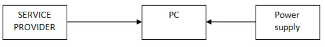
Fig 2: Receiver Side
Bridge Rectifier
When four diodes are connected as shown in figure, the circuit is called as bridge rectifier. The input to the circuit is applied to the diagonally opposite corners of the network, and the output is taken from the remaining two corners. Let us assume that the transformer is working properly and there is a positive potential, at point A and a negative potential at point B. The positive potential at point A will forward bias D3 and reverse bias D4. The negative potential at point B will forward bias D1 and reverse D2. At this time D3 and D1 are forward biased and will allow current flow to pass through them; D4 and D2 are reverse biased and will block current flow. The path for current flow is from point B through D1, up through RL, through D3, through the secondary of the transformer back to point B. this path is indicated by the solid arrows. Waveforms (1) and (2) can be observed across D1 and D3.One-half cycle later the polarity across the secondary of the transformer reverse, forward biasing D2 and D4 and reverse biasing D1 and D3. Current flow will now be from point A through D4, up through RL, through D2, through the secondary of T1, and back to point A. This path is indicated by the broken arrows. The current flow through RL is always in the same direction. In flowing through RL this current develops a voltage corresponding to that shown waveform (5). Since current flows through the load (RL) during both half cycles of the applied voltage, this bridge rectifier is a full-wave rectifier.
Signal Conditioning Circuits
Humidity Sensor
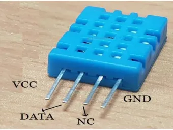
Humidity is the presence of water in air. The amount of water vapor in air can affect human comfort as well as many manufacturing processes in industries. The presence of water vapor also influences various physical, chemical, and biological processes. Humidity measurement in industries is critical because it may affect the business cost of the product and the health and safety of the personnel. Hence, humidity sensing is very important, especially in the control systems for industrial processes and human comfort. Controlling or monitoring humidity is of paramount importance in many industrial & domestic applications. In semiconductor industry, humidity or moisture levels needs to be properly controlled & monitored during wafer processing. In medical applications, humidity control is required for respiratory equipment’s, sterilizers, incubators, pharmaceutical processing, and biological products. Humidity control is also necessary in chemical gas purification, dryers, ovens, film desiccation, paper and textile production, and food processing. In agriculture, measurement of humidity is important for plantation protection (dew prevention), soil moisture monitoring, etc. For domestic applications, humidity control is required for living environment in buildings, cooking control for microwave ovens, etc. In all such applications and many others, humidity sensors are employed to provide an indication of the moisture levels in the environment.
Fig 3: DHT11 Humidity Sensor
Temperature Sensor
Flame Sensor
A flame detector is a sensor designed to detect and respond to the presence of aflame or fire. Responses to a detected flame depend on the installation, but can include sounding an alarm, deactivating a fuel line (such as a propane or a natural gas line), and activating a fire suppression system.
One advantage of a bridge rectifier over a conventional full-wave rectifier is that with a given transformer the bridge rectifier produces a voltage output that is nearly twice that of the conventional full-wave circuit. This may be shown by assigning values to some of the components shown in views A and B. assume that the same transformer is used in both circuits. The peak voltage developed between points X and y is 1000 volts in both circuits. Since only one diode can conduct at any instant, the maximum voltage that can be rectified at any instant is 500 volts. The maximum voltage that appears across the load resistor is nearly-but never exceeds-500 v0lts, as result of the small voltage drop across the diode. Current flows through the load during both half cycles of the applied voltage. In the bridge rectifier shown in view B, the maximum voltage that can be rectified is the full secondary voltage. Therefore, the peak output voltage across the load resistor is nearly 1000 volts. With both circuits using the same transformer, the bridge rectifier circuit produces a higher output voltage than the conventional full-wave rectifier circuit. In the conventional full-wave circuit, the peak voltage from the center tap to either X or Y is 500 volts. The path for current flow is from point B through D1, up through RL, through D3, through the secondary of the transformer back to point B. this path is indicated by the solid arrows. Waveforms (1) and (2) can be observed across D1 and D3.One-half cycle later the polarity across the secondary of the transformer reverse, forward biasing D2 and D4 and reverse biasing D1 and D3. Current flow will now be from point A through D4, up through RL, through D2, through the secondary of T1, and back to point A. This path is indicated by the broken arrows. The current flow through RL is always in the same direction. In flowing through RL this current develops a voltage corresponding to that shown waveform (5). Since current flows through the load (RL) during both half cycles of the applied voltage, this bridge rectifier is a full-wave rectifier.
Temperature Sensor
The LM35 series are precision integrated-circuit temperature sensors, whose output voltage is linearly proportional to the Celsius (Centigrade) temperature. The LM35 thus has an advantage over linear temperature sensors calibrated in ° Kelvin, as the user is not required to subtract a large constant voltage from its output to obtain convenient Centigrade scaling. The LM35 does not require any external calibration or trimming to provide typical accuracies of ±¼°C at room temperature and ±¾°C over a full -55 to +150°C temperature range. Low cost is assured by trimming and calibration at the wafer level. The LM35's low output impedance, linear output, and precise inherent calibration make interfacing to readout or control circuitry especially easy. It can be used with single power supplies, or with plus and minus supplies. As it draws only 60 µA from its supply, it has very low self-heating, less than 0.1°C in still air. The LM35 is rated to operate over a -55° to +150°C temperature range. A digital thermometer can be easily created by using LM35 temperature sensor and can be interfaced any microcontrollers. The LM 35 IC generates a 10mV variation to its output voltage for every degree Celsius change in temperature. The Output of the temperature sensor is analog in nature so we need an analog to digital converter for converting the analog input to its equivalent binary output. The ADC 0804 is the analog to digital converter IC used in the project. 0804 is a single channel converter which converts the analog input up to a range of 5V to an equivalent 8-bit binary output.
MAX 232
RS232 inputs to 5V TTL/CMOS levels. These receivers (R1 & R2) can accept ±30V inputs. The drivers (T1 & T2), also called transmitters, convert the TTL/CMOS input level into RS232 level. The transmitters take input from controller’s serial transmission pin and send the output to RS232’s receiver. The receivers, on the other hand, take input from transmission pin of RS232 serial port and give serial output to microcontroller’s receiver pin. MAX232 needs four external capacitors whose value ranges from 1µF to 22µF.
Fig 4 Pin Diagram – MAX 232
GSM Module
Fig 5 SM9100 Module
IV.DESIGNMETHODOLOGY
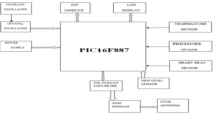
In this design, the PIC microcontroller is used as a gateway communicate to the various sensors such as temperature sensor, heartbeat sensor, ECG sensor, sensor for keeping a track of drip level (blood or saline).The microcontroller picks up the sensor data and sends it to the network through a Wi-Fi and hence provides real time monitoring of the health care parameters for doctors.• The controller is also connected with buzzer to alert the caretaker about variation in sensor output. At the time of extremity situation alert message is sent to the doctor through the android application connected to the cloud server. Hence quick provisional medication can be easily done by this system. Also an additional subsystem is provided for prediction of heart disease for the patient based on his/her health parameters. This system is efficient with low power consumption capability, easy setup, high performance and time to time response.
V. CONCLUSION
By using the system the healthcare professional can monitor, diagnose and advise their patients all the time. The health parameters data are stored and published online. Hence, the healthcare professional can monitor their patients from a remote location at any time. Our system is simple and patient's data can be easily accessed. The entire concept of IOT stands on sensors, gateway and wireless network which enable users to communicate and access the application/environment. The Future work of the project is very essential in order to make the design system more advanced. In the designed system the enhancement would be connecting more sensors to internet which measures various other health parameters and would be beneficial for patient monitoring i.e. connecting all the objects to internet for quick and easy access. Establishing a Wi-Fi mesh type network to increase in the communication range.
REFERENCES
[1] V. PersisPriyanka, K. Sudhakar Reddy, “Identifying the Changes through PIR by Transmitting the Video and Providing a Security”, International journal of professional engineering studies, June 2015.
[2] CheahWai Zhao, CheahWai Zhao, Son Chee Loon, “Exploring IOT application using raspberry pi”, International Journal of Computer Networks and Applications,, February 2015.
[3] Mrs.ReenaP.Shinde, Mr.YogeshN.Gatlawar, "Automated Environment Monitoring And Control System For Agro-Based Industries Using Wireless Sensor Networks," International Journal of Research in Advent Technology Special National Conference “ACGT2015”,, February2015.
[4] Sneha Singh PradnyaAnap,YogeshBhaigade, Prof.J.P.Chavan,"IpCamera Video Surveillance Using Raspberry Pi,"International Journal of Advanced Research in Computer and Communication Engineering,February 2015.
[5] Li Da Zu” Internet of Things in Industries: A Survey” IEEE Transactions on Industrial Informatics, November 2014 . [6] Sadeque Reza Khan Professor Dr. M. S. Bhat “GUI Based Industrial Monitoring and Control System ``IEEE paper, 2014. [7] P.Deepika,P.Vinothini,Research Paper Heart Disease Analysis And Prediction Using Various Classification Models,Volume :
4 | Issue : 3 | Mar 2015 , ISSN – 2250-1991.