Modelling of Pellet Cladding Interaction in PWR fuel
Jacqueline BROCHARD 1), Fabrice BENTEJAC 1), Nicolas HOURDEQUIN 1), Sandrine SEROR 1), Caroline VERDEAU 1), Olivier FANDEUR 1), Sylvie LANSIART 2), Pierre VERPEAUX 3)
1)CEA CENTRE DE SACLAY, SEMI/LEMO, F-91191 GIF-SUR-YVETTE CEDEX, FRANCE 2)CEA CENTRE DE CADARACHE, DEC/IPG, F-13108 ST PAUL LEZ DURANCE CEDEX, FRANCE 3) CEA CENTRE DE SACLAY, SEMT, F-91191 GIF-SUR-YVETTE CEDEX, FRANCE
ABSTRACT
Refined Finite Element (FE) mechanical modelling of the PWR fuel rod is in progress in view of an accurate evaluation of the relevant parameters that govern the PCI/SCC (Pellet Cladding Interaction / Stress Corrosion Cracking) cladding failure mechanism. In addition to the materials constitutive laws, which are not discussed in this paper, the pellet fragmentation and friction at pellet-cladding interface have been identified as two major phenomena to be taken into account for a precise calculation of the cladding mechanical state. These developments have been integrated in the TOUTATIS code, in order to be tested on the fuel rod mechanical response during a complete irradiation. The quality of the modelling is evaluated by comparing the calculated values to the residual cladding diametral measurements and dish fillings. Taking into account the transversal pellet fragmentation, in addition to radial pellet fractures improve the prediction of the axial cladding deformation profile. As concerns the mechanical contact at pellet-cladding interface, a sensitivity study conducted on a refined 2D model shows up that the local cladding mechanical state in front of a pellet crack is not so dependant of the friction coefficient in the variation range identified through out-of-pile experiments. Calculations performed with such FE modelling contribute to a better understanding of the PCI mechanisms. Moreover the improvement of the simulation of the pellet-cladding deformation with the recent developments let us be confident of the interest of such a numerical tool for the cladding failure forecast, using the relevant mechanical parameters and a suitable damage model.
INTRODUCTION
During normal and incidental PWR operating conditions, the reactor manoeuvrability is limited by the prevention against fuel rod cladding failure by PCI/SCC (Pellet-Cladding Interaction/Stress Corrosion Cracking) for severe power transients. To reduce this penalty, the Pellet-Cladding Interaction modelling is under development in the framework of the CEA PCI research project, in order to contribute to a better understanding of the PCI mechanisms and to help in the selection of remedies.
In order to obtain an accurate evaluation of the cladding mechanical state, refined Finite Element (FE) modelling is being developed at the pellet scale of the fuel rod. Thus the simulation of the fuel rod mechanical behaviour, in nominal operating and transient conditions, has been programmed in the TOUTATIS code [1], which is based on the general FE code CASTEM 2000 [2], to solve the mechanical equilibrium of the pellet-cladding system taking into account geometrical and material non-linearities.
Two main developments are in progress to improve the mechanical state forecasts. On the one hand, pellet fragmentation assumptions are analysed since cladding deformations are extremely dependent upon them. On the other hand, friction is introduced in the pellet-cladding interface modelling. The first objective of this development is to evaluate the stress concentration in the cladding in front of a pellet crack and the second objective will be to improve the axial pellet-cladding relation, which is currently modelled with a pinpointed locking condition. Applications of these developments in the simulation of experimental power transients on pre-irradiated fuel rods are done to estimate the improvements. Comparisons between numerical and experimental results focus on the cladding residual diametral deformations and dish fillings.
PCI MECHANICAL PHENOMENA
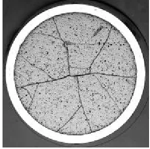
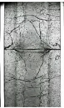
During the first power increase to nominal conditions, the fuel pellets are fractured by the internal stresses due to the restrained thermal expansion (thermal gradient : 450°C for 4 mm in radius). A typical fragmentation is shown in Fig. 1 and 2. Schematically a pellet is
SMiRT 16, Washington DC, August 2001 Paper # 1314
At the beginning of the irradiation, the cladding is subjected to the differential pressure (coolant pressure minus internal gas pressure) and creeps in compression due to this loading. Progressively the pellet-cladding gap closes under the combined effect of the cladding creep and the pellet swelling induced by fission product accumulation. Due to the hourglassing pellet shape, the first contact occurs at the inter-pellet level where the gap is the lowest. Between the inter-inter-pellet planes, the cladding continues to creep up to take the exact inter-pellet shape. This mechanism has been correlated with the remanent “primary” ridges identified on the cladding diametral measurements after irradiation.
Fig. 1 Transversal macrography of a fuel rod irradiated
for two annual PWR operating cycles Fig. 2 Axial macrography of a fuel rod irradiated for two
annual PWR operating cycles
While the gap closes, the cladding, initially loaded in compression, progressively gets in contact with the pellets and becomes loaded in tension. The tensile stress increases slowly up to about 20 to 30 MPa, which corresponds to an equilibrium value, according to the cladding creep rate and the pellet swelling rate. So, in nominal conditions, the cladding easily accommodates the pellet swelling kinetic by a neutron flux activated creep deformation : the cladding is loaded by low PCI.
During transients (power ramps), the thermal gradient largely and quickly increases to reach within a few minutes a value almost three times higher than the nominal value (1200°C for 4 mm in radius). The corresponding pellet dilatation leads to a strong pellet thrust on the cladding. So, high tensile stresses are induced in the cladding, which cannot easily accommodate by viscoplasticity such a thermal expansion. Meanwhile, due to the high temperatures, the fuel viscoplasticity is also activated in the pellet centre and leads to a progressive filling of the transversal cracks as well as the dishings. The fuel creep has been identified on macrographies (Fig. 3) and is correlated with the formation of “secondary” ridges at the median pellet plane level (Fig. 4). In such strong PCI conditions, the mechanical state of the pellet-cladding system is no more governed by the pellet deformation. In fact, the stiffnesses of the fragmented pellets and the cladding are no more so different and the strong cladding mechanical pre-stressing contributes to unbend the fragmented pellets. The high tensile stresses combined with a chemically aggressive environment (corrosive fission products) may lead to a cladding failure by a PCI/SCC mechanism [4] [8] (Fig. 5). Consequently, PCI is taken into account in fuel rod design to avoid such a risk for power transient of class 2 incident.
During the hold period at Ramp Terminal Level (RTL), the fuel gaseous swelling, activated by the high temperatures, also increases the pellet expansion. This phenomenon is all the more significant that the power level and the fuel burnup are high and the hold period long. However, its kinetic is low in comparison with the instantaneous thermal dilatations and thus its contribution to the PCI/SCC mechanism is less important since cladding failures generally occur in the first minutes at RTL.
Fig. 3 Axial macrography of a fuel rod irradiated for two annual PWR operating cycles and subjected to a power ramp until 45.7 kW/m
maintained almost 7 min. at RTL
Fig. 5 SCC cladding failure
Fig. 4 Diametral measurements before and after a power ramp test (45.7 kW/m, 7 min at RTL) for a fuel rod irradiated for two annual PWR operating cycles. Zoom on
the axial level which experienced maximal power.
Fig. 6 Typical evolution of the cladding circumferential stress as function of time
during a power ramp test
THE TOUTATIS CODE
The main objective of the TOUTATIS code is to propose the modelling and computing scheme suitable for an accurate simulation of the cladding mechanical behaviour in PCI conditions, taking into account material and geometrical non-linearities such as:
Ø fuel creep activated by fissions or by high temperatures in the pellet centre Ø cladding viscoplasticity activated by the fast neutron flux or by high stresses
Ø contacts between surfaces warped by the thermal gradient (lateral surfaces or bases of a pellet fragment) Cladding
Fuel
UO2 pellet cracking
9425 9445 9465 9485
55 85 115 145
Axial position (mm)
Cladding diameter (µm)
After PWR irradiation
After power ramp test Inter-pellet levels
-50 25 100 175 250 325 400
Time
Cladding circumferentiel stress
Using the FE method, the mechanical equilibrium is obtained by the resolution step by step of the following equations system : K(T,X) ∆U= ∆Fexternal + ∆Finelastic + additional equations for boundary conditions and unilateral contacts,
with U nodal displacement vector
K(T,X) stiffness matrix, function of temperature T and irradiation parameters X Fexternal pressure forces, effects due to thermal dilatation and swelling
Finelastic inelastic forces due to the non-linear material behaviours
Where the non-linear material behaviours are described by constitutives laws : dεinelastic/dt=f(σ,εinelastic, V,T,X) with V internal variables
and ∆ε = ∆εelastic + ∆εinelastic + ∆εthermal + ∆εswelling
∆σ = H ∆εelastic with H: Hooke matrix
Since the pellet-cladding system accumulates inelastic deformations, especially with the formation of the “primary” ridges on the cladding, its initial state before a power ramp has to be taken into account for an accurate prediction of the mechanical state during the transient. In consequence, the computing scheme [7] developed in the TOUTATIS code is based on a complete simulation of the fuel rod irradiation in nominal and transient conditions.
The main phenomena taken into account within the TOUTATIS code are:
- in nominal conditions: thermal dilatation, in-pile fuel densification and fuel swelling, cladding creep under the coolant/rod differential pressure, evolution of the fuel-cladding gap thermal conductance, PCI which involves the formation of ridges on the cladding at pellet interfaces;
- in transient conditions: intensification of PCI due to the fuel temperature increase, internal fuel creep and cladding viscoplasticity under high stresses.
Since the development of the first 2D(r,z) discretization [5], more accurate modellings have been developed and still are in progress. In the current version [6], the 3D modelling presents the following characteristics :
-to take into account the fragmentation due to nominal conditions, fuel pellets are assumed to be pre-fractured into equal fragments (classically four or eight) by radial cracks extending to the fuel center line, this hypothesis being acceptable since fuel fracture occurs at the early stage of irradiation. This idealized fracture pattern has been suggested by radial macrographies (Fig. 1);
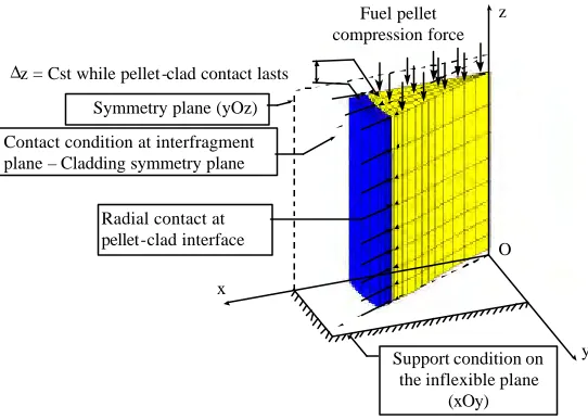
- using suitable boundary conditions, the discretization is limited to one quarter of a pellet fragment and the associated cladding portion (Fig. 7). By symmetries, this volume can be considered as representative of the total rod.
- concerning the mechanical conditions at pellet-cladding interface, the imposed relations are:
. contact without friction in the circumferential direction
. no axial relative movement between pellets and cladding at mid-pellet level when contact is established. For the simulations presented afterwards, material properties and models used are those detailed in [1].
Fuel pellet compression force
∆z = Cst while pellet-clad contact lasts
Support condition on the inflexible plane
(xOy) Symmetry plane (yOz)
Contact condition at interfragment plane – Cladding symmetry plane
z
y x
O Radial contact at
FRAGMENTATION MODEL DEVELOPMENT
Many computations have now been done using the current 3D model with radial fragmentation which proves to give more accurate results than the 2D(r,z) unfragmented model. In fact, two main limitations have been identified for the 2D model:
- the overestimation of the stress gradient using the unfragmented model leads to an activation of the creep mechanism in the pellet center zone even in nominal conditions. Consequently, the calculation predicts a partial dish filling after two annual cycle base irradiation (15% dish filling for applications presented in [6]), whereas no dish filling is observed on macrographies;
- the monobloc cylinder configuration represented by the unfragmented model leads to overestimate the pellet cylinder stiffness and restrain pellet global deformation mechanisms. Consequently, on the one hand the displacement controlled mechanism imposed by the pellets on the cladding is excessive; on the other hand the bending mechanism of the pellet fragment is not reproduced and the “secondary” ridges are not represented.
But, even if the radially fragmented 3D model seems to be more accurate than the 2D(r,z) model, it presents an artifact since secondary ridges are proved to be overestimated in comparison with measured values [6]. In fact, due to the inelastic strain accumulation in the pellet during the irradiation, the pellet gets a barrel shape after unloading and, consequently, the pellet remains in contact with the cladding at mid pellet level. This remanent PCI leads to the formation of secondary ridges in the elastic range (Fig. 8).
In order to verify if this artefact is correlate or not to the account of the transversal pellet fracture, new calculations have been recently performed with the 3D model, considering both radial and transversal fragmentations: the pellet is assumed fractured by eight radial cracks and three transversal cracks extending to the fuel center line.
Fig. 8 Pellet global deformation mechanism
Fig. 10 Cladding deformation after two annual cycle base irradiation as a function of
axial position along the pellet
Fig. 9 Radial distribution of the axial stress in the pellet for nominal conditions
Fig. 11 Cladding deformation for a fuel irradiated during two annual cycle after a power ramp as a function of axial position along the pellet
0 4 7 11 14
Distance to inter-pellet plane (mm)
Radial displacement (µm)
Unfragmented pellet system Fragmented pellet system
0 4 7 11 14
Distance to inter-pellet plane (mm)
Radial displacement (µm)
Unfragmented pellet system Fragmented pellet system
of the mid-pellet overdeformation although there is still a slight PCMI effect at this location. Thus, the computed deformations present a better agreement with experimental values.
CONTACT WITH FRICTION AT PELLET-CLADDING INTERFACE
During a severe transient, under the combined effects of the high tensile stresses due to PCI and corrosive fission products, Stress Corrosion (SCC) typical cracks may appear primarily in front of radial cracks of the pellets, at the precise point where the stress values and the amounts of corrosive fission products are maximum [3] (Fig. 5).
The forecast of the failure mechanism requires an accurate calculation of the relevant parameters, such as stress, strain and strain rate, in the failure zone. Thus, both pellet fragmentation and pellet-cladding contact with friction have to be introduced in the modelling.
As concerns the pellet-cladding contact with friction, the classical Coulomb law is considered. On the one hand, a bibliography of pellet-cladding friction coefficient measurements has been carried out in order to determine its variation range. On the other hand, a 2D(r,θ) model has been developed to study the influence of this parameter on the cladding mechanical state.
Bibliography of pellet-cladding friction coefficient measurements
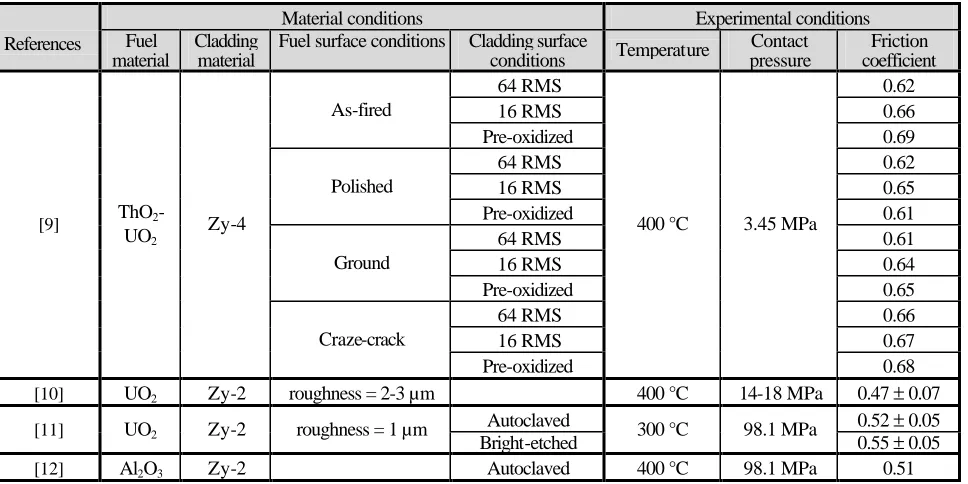
The experimental set-up used by most of the authors [9] [10] [13] consists in characterizing a plane-plane interface, either with a pellet basis in contact with a Zircaloy plane sample, or with a UO2 disk between two Zircaloy disks or vice-versa. However, Nakatsuka and al. [11] [12] have analysed the contact between two concentric surfaces, which is the most representative of the real fuel rod geometry. Most of the characterizations have been achieved out-of-pile, the results given in [13] seem to be the single experiments performed in-pile.
Different experimental conditions or material surface qualities have been considered by the authors to evaluate their influence on the friction coefficient. Table 1 summarizes the compilation results for out-of-pile experiments at high temperature, considering only influential parameters. Finally the variation range is not so important since the friction coefficient ranges from µ = 0.4 to µ = 0.69. However in-pile experiments results are shifted to upper values : 0,4 ≤ µ ≤ 1,2. In the experimental conditions the most representative of a power transient in a PWR fuel rod (T≈ 350°C; Pcontact = 100MPa), the results obtained are : 0.47 ≤µ≤ 0.60 [11].
Table 1. Compilation of the friction coefficient measured in out-of-pile conditions
Material conditions Experimental conditions
References Fuel material
Cladding material
Fuel surface conditions Cladding surface
conditions Temperature
Contact pressure
Friction coefficient
64 RMS 0.62
16 RMS 0.66
As-fired
Pre-oxidized 0.69
64 RMS 0.62
16 RMS 0.65
Polished
Pre-oxidized 0.61
64 RMS 0.61
16 RMS 0.64
Ground
Pre-oxidized 0.65
64 RMS 0.66
16 RMS 0.67
[9] ThO2 -UO2
Zy-4
Craze-crack
Pre-oxidized
400 °C 3.45 MPa
0.68 [10] UO2 Zy-2 roughness = 2-3 µm 400 °C 14-18 MPa 0.47 ± 0.07
Autoclaved 0.52 ± 0.05
[11] UO2 Zy-2 roughness = 1 µm
Bright-etched 300 °C 98.1 MPa 0.55 ± 0.05
2D (r, θ, θ) model and sensitivity study
In order to easily perform sensitivity studies, a 2D(r,θ) model, with both radial fragmentation and friction at pellet-cladding interface, has been developed. A generalized plane strain condition is considered in order to be the most representative of the mid-pellet conditions. For a pellet supposed radially fragmented in 8 sectors and taking into account symmetry conditions, 1/16 pellet is modelled with the corresponding cladding portion (Fig. 12). The out-of-plane condition is a uniform displacement. Before pellet-cladding contact, pellet and cladding axial displacements are independent. When the contact is detected, the axial condition is modified to imp ose that there is no axial relative movement between pellet and cladding.
To analyse the influence of the friction coefficient value on the cladding mechanical state, an irradiation has been simulated with this model on a two cycle equivalent fuel rod (reduced cladding-fuel initial gap, adapted constitutive laws and thermal conductivity) : a conditioning period of 24 hours at 15 kW/m and a power ramp up to 42 kW/m at 10 kW/m/min with a hold period of 2 hours at RTL. Several calculations have been performed with friction coefficient values ranging from µ = 0 to µ = 2. A typical deformed shape of the pellet-cladding system is visualised on Fig. 13 : the fragment bulging due to the radial thermal gradient (schematically presented on Fig. 12) is limited by the contact with friction, which induces a hoop stress concentration at the cladding inner surface in front of the pellet crack. A significant strain concentration is induced in the same spot by this pellet restrained deformation, as an example the strain amplification is equal to 4 for µ = 0.52 (Fig. 14). Figure 15 presents the circumferential stress in the cladding, in front of a pellet crack, measured to the current value as function of the friction coefficient. In the variation range of the out-of-pile friction coefficient, the stress concentration does not vary in an important way. The same result is obtained for the inelastic hoop strain.
y
x
Fig 12 Schematic of the represented part with the 2D(r,θθ) model
Fig 13 Hoop stress and contact forces on a typical deformed shape using the 2D(r,θθ) model
3,0E-03 5,0E-03 7,0E-03 9,0E-03 1,1E-02 1,3E-02
Inelastic hoop strain
µ = 0
µ = 0,1
µ = 0,2
µ = 0,3
µ = 0,4
µ = 0,52
µ = 0,7
µ = 1,2
µ = 2
1,40 1,34 1,43 1,35 6,48E-03 1,14E-02 6,90E-03 1,20E-02 0,47 0,6 0,9 1 1,1 1,2 1,3 1,4 1,5 1,6 1,7 1,8 k = σθθ max / σθθ mean 0,004 0,006 0,008 0,01 0,012 0,014
Maximal hoop inelastic strain
Top of the ramp After 2 h at RTL
CONCLUSIONS
Refined FE mechanical modellings are being developed within the TOUTATIS code for an accurate evaluation of the local mechanical state in the cladding in front of a pellet crack at the precise location where Stress Corrosion Cracking may appear. Simulations show up that taking into account the pellet fragmentation is important for an accurate forecast of the pellet-cladding mechanical response at both global and local levels.
Globally, the deformation of the fragmented pellet is not restrained as for a monobloc pellet. Moreover its apparent stiffness is not so different than the cladding stiffness in power ramp conditions. Consequently, a representative pellet fragmentation is required for a precise evaluation of the cladding global deformation.
Locally, a pellet fracture induces a stress concentration in the cladding. A sensitivity study has been achieved in order to evaluate the variation range of the stress concentration as a function of the pellet-cladding friction coefficient. The results of this analysis are promising since, for the friction coefficient variation range identified by a survey on out-of-pile characterizations, the variation of the stress evaluation is lower than 10%.
ACKNOWLEDGMENT
The present study has been partly carried out in the framework of a collaborative program with EDF and FRAMATOME. The authors wish to thank gratefully the related persons for their financial support and informative discussions.
REFERENCES
1. Brochard, J., Bentejac, F. and Hourdequin, N., “Nonlinear finite element studies of the pellet-cladding mechanical interaction in a PWR fuel,” Proc. of the 14th International Conference on Structural Mechanics in Reactor Technology, Paper CW/4, pp. 271-278, Lyon, France, August, 1997.
2. Verpeaux, P., Charras, T. and Millard, A., “CASTEM 2000 : une approche moderne du calcul des structures” Calcul des structures
et intelligence artificielle, Pluralis, Paris, 1988.
3. Bailly, H., Menessier, D., Prunier, C., The NUCLEAR FUEL of PRESSURIZED WATER REACTORS and FAST REACTORS
design and behaviour, Eyrolles, Paris, 1995.
4. Fandeur, O., Rouillon, L., Pilvin, P., Rebeyrolle, V., Jacques, P., “Modelling of Stress Corrosion Cracking in zirconium alloys,” Proc.
of the IAEA TCM, Nuclear Fuel Behaviour Modelling at High Burnup and its Experimental Support, Windermere, U.K.,
June, 2000.
5. Bourreau, S., Lansiart, S., Couffin, P., Verdeau, C., Decroix, G.-M., Grandjean, M.-C., Hugot, H., Mermaz, F., Vanschel, E., “Influence of hold time on the fuel rod behaviour during a power ramp,” IAEA-TECDOC-1179, Fuel Chemistry and Pellet-Clad Interaction related to High Burnup Fuel, pp. 63-73, Niköping, Sweden, September, 1998.
6. Bourreau, S, Brochard, J., Bentejac, F., Couffin, P., Verdeau, C., Lansiart, S., Cayet, N., Grandjean, M.C., Mermaz, F., Blanpain. P., ”Ramp testing of PWR fuel and multi-dimensional finite element modeling of PCMI,” Proc. of the 2000 International Topic
Meeting on Light Water Reactor Fuel Performance, Park City, Utah, April, 2000.
7. Bentejac, F, Hourdequin, N., Bourreau, S., Brochard, J., Lansiart, S., Delette, G., “Fuel rod modeling during transients: the TOUTATIS code” Proc. of the IAEA TCM, Nuclear Fuel Behaviour Modelling at High Burnup and its Experimental Support, Windermere, U.K., June, 2000.
8. Davies, J. H., Rosenbaum, H. S., Armijo, J. S., Proebstle, R. A., Rowland, T. C., Thompson, J. R., Esch, E. L., Romeo, G., Rutkin, D. R., “Irradiation tests to characterize the PCI failure mechanism,” Proc. of the ANS Topical meeting on Water Reactor Fuel
Performance, pp. 230-242, 1977.
9. Swota, J., Wisnyi, L.G. and Schreiner, W.A., “Friction tests between ThO2-UO2 and Zircaloy-4,” General Electric Company
report, No. KAPL-3166, 1966.
10. Tachibana, T., Narita, D., Kaneko, H. and Honda, Y., “Measurement of the friction coefficient between UO2 and cladding tube,” Proc.
of the Fall Meeting of the Atomic Energy Society of Japan, PNCT 831-78-02, October 1977.
11. Nakatsuka, M., “ Measurement of the coefficient of friction between UO2 and Al2O3 pellets and Zircaloy cladding,” Journal of
Nuclear Materials, Vol. 96, 1981, pp. 205-207.