Strength of Overlapping Multi-Planar “KK”
Joints in CHS Sections
Peter Gerges 1, Mohamed Hussein1, Sameh Gaawan 2
Structural Engineer, Department of Structures, Dar Al-Handasah Consultants, Giza, Egypt1
Associate Professor, Department of Structures, Faculty of Engineering, Mataria branch, Helwan University,
Cairo, Egypt2
ABSTRACT: Hollow steel section is always preferred architecturally due to its aesthetic appearance, also it provides reduced weight and surface area when compared to open section and it is also preferred structurally. Thus, it is essential for a designer to be aware of the design of common connections of such sections. Overlapped KK connections is one of the connections that may face many engineers as this connection is the main item to form three chorded truss that is widely used in architectural designs. However, the design of overlapped multi-planar joints isn’t covered by international design codes, design guides, and also not addressed extensively in previous researchers. In this paper, a parametric study is carried out to investigate the effect of the chord radius to thickness ratio (ɣ), brace thickness to chord thickness ratio (), the brace diameter to the chord diameter ratio (β) on the capacity of multi-planar KK connections and comparing this capacity with that of uniplanar K-connections. Providing that the CHS connections are unstiffened, the hidden seam are welded. The parametric study based on validated finite element models that are calibrated with previous laboratory tests results, the average error of these models equals to 2.54%. The CHS KK joint capacity in the study ranges from 73% to 100% of the CHS K joint capacity.
KEYWORDS: Tubular joints, Unstiffened, overlapped, CHS KK-joints, Multi-planar, correction factor, Ultimate capacity.
I. INTRODUCTION
The axially loaded K joint is a main component of warren truss. This joint is classified into gapped joint and overlapped joint. The capacity of the gap K joint increases as the gap value decreases. This is because of that, the plastic deformation of the chord at the gap location increases by increasing the gap value, and the joint tends to brittle response. Where decreasing the gap between the braces has beneficial effect on the joint capacity, the negative gap is provided to create the overlapped K joints. Due to the common area between the two braces in overlap K joints, the load transfers between braces and chord in more directness, and joint capacity increases with more ductile behaviour compared to gaped joints. However, the common welding area and multiple cutting in the overlapping brace member cause high fabrication complications which affects the fabrication cost.
The extension of the study of axially loaded K joints is the study of multi planner K joints which called KK joints. The KK joint is an essential term in three chorded trusses configuration. The KK joints have a close behaviour compared to K joints. The overlapped KK joint has the same strength benefit compared to the gapped KK joints; which is the case in the K joints. However, fabrication difficulties and cost are higher than the case of K joints, as there are more cut bracing elements and common welds. Form the previous researches, it has been concluded that, the hidden seem weld has no significant effect on the strength of the joint -especially if the through braces are subjected to compression-. However, in this paper, it is assumed that CJP weld is provided for all braces including the hidden seem part to exclude the welding effect from the study.
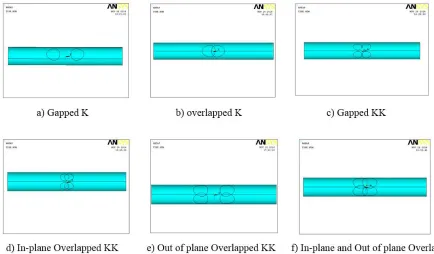
There are more than one condition. As the overlapping may take place between: the in-plane braces, the out of plane braces and in plane and out of plane brace which is the objective of this study.Figure1 shows that classification in details as it shows six different types for K and KK connections.
II. RELATED WORK
As for the uniplanar K connections, Dexter and Lee (1999) studied the static behavior of axially loaded tubular K-joints and the mode failure of such joints. The mode of failure of axially loaded overlapped K-joints was either due to chord bending, brace local buckling or a combination between chord bending and brace local buckling. Also the effect of different geometric parameters on that behavior was investigated. While Zaho, Chen, Chen, Wang et. al. (2006) tested seven uniplanar overlapped CHS K-joints specimen with hidden seam un-welded to study the geometric parameters effect on the joint capacity, another three specimens -but with welded hidden seam- were tested. The results of the tests showed that welding situation on the hidden seam has insignificant effect of the joint capacity. Chen, Zhao and Chen (2008) simulated unstiffened overlapped CHS K-joints by using finite element models and compared the ultimate capacities, deformation processes and failure modes obtained from the FEM with that of previous experimental tests, also carried out a parametric study on unstiffened CHS overlapped K joint. Based on that parametric study, the joint capacity results were compared to that of gap joints calculated by the design equation. As for the multi-planar CHS gap KK joints, many papers were carried out to study these joints behaviour and capacities, from that papers and researchers, Makino et al. started to study the multi-planar CHS gap KK in 1984 by testing 20 CHS KK joints. Lee and Wilmshurst in 1995 performed a numerical study on CHS gap KK joints to investigate the effect of weld geometry, boundary conditions at chord and brace ends, mode of loading, chord length and material properties on the joints capacity. While in 1996 M. M. K. Lee & S. R. Wilmshurst focused on studying the effect of ɣ on the joint strength, also strength equations were formulated through multiple regression analyses. Recently in 2015 Forti, Requena and Forti carried out a parametric study on 54 CHS KK gap connections and their corresponding uniplanar K connections and as
a result of this study an analytical expression was proposed to predict CHS KK gap connection capacity based on the geometric parameters and the resistance of the corresponding uniplanar K connection. Very limited number of researches studied multi-planar CHS overlapped KK connections, Zhao, Han, Hu, Chen and Wu (2015) are from those who studied such complicated connections. In that paper, four specimens with in-plane overlapped braces were tested and investigated the effect of presence or absence of hidden welds, presence of vertical stiffener for avoiding partial overlapping of one brace member onto another, and symmetric or anti-symmetric axial loading. This paper conclusion was that welding situation of hidden seam and the presence of vertical stiffener don’t effect significantly the joint capacity, the ultimate capacity of the multi-planar overlapped KK-joint decreased a lot when subjected to anti-symmetric loading.
III.FINITE ELEMENT MODELLING
Limited number of laboratory tests were carried out to study the circular hollow sections overlapped connections in particular the multi-planar overlapped KK connections. In order to overcome that shortage, the calibration were done against two overlapped K-connections tests, four gapped KK planar connections tests, and two overlapped multi-planar KK-connections. Table 1 represents the capacity obtained from the tests against that obtained from the finite element models. The errors in below table 1 are of accepted values, thus the FEM results are reliable and this simulation can be used in the parametric study. The calibrated FEM are described in details in the following section.
Table 1Calibrated FEM results against laboratory results
Reference Connection type Specimen ID Test capacity
(KN)
FEM capacity (KN)
Error %
Makino et al.
(1984) multi-planargapped KK
DK-1 82.9 83.2 0.36%
DK-2 107.9 103.7 3.9%
DK-3 149.1 155 4%
DK-10 136.3 136.1 0.15%
Zhao et. al 2015 Overlapped KK
multi-planar
IPOv-W 1392.5 1364 2.05%
IPOv-N-A 1275.2 1288 1%
Zhao, Chen et. al 2006
Overlapped K uniplanar
SJ1 1373 1381 0.58%
SJ4 1209 1109 8.3%
average error 2.54%
a. Element type and meshing
The finite element models were carried out using software ANSYS 14. The steel elements in these models are simulated by using four node strain shell element “Shell 181” that is included in ANSYS elements library as the properties of this type of element is convenient for such simulation. Here is a brief description for the used shell element type: SHELL181 “is suitable for analyzing thin to moderately-thick shell structures. It is a four-node element with six degrees of freedom at each node: translations in the x, y, and z directions, and rotations about the x, y, and z-axes. SHELL181 is well-suited for linear, large rotation, and/or large strain nonlinear applications”. (Figure2) shows the geometry, node locations, and the element coordinate system for this element.
As for the meshes size it was found that using size of 25 mm gives accurate realistic results when compared with that obtained from laboratory tests. However in the parametric study, meshes size ranges from 15 to 25 are used in order to avoid any irregular shapes.
b. Material mechanical properties
The material mechanical properties in the finite element modeling are simulated by a bilinear isotropic hardening elastic perfectly plastic material. The material properties of the chord and brace of each model are as the following Young’s modulus (E=2100 N/mm2), the yield stress (fy= 355N/mm2).
c. Loading and boundary conditions
In the parametric study, the chord length, brace length are fixed in all the FEM which are 1500 mm, 750 mm
respectively. Thick plates are placed at the chord and braces ends, the brace axial loads are applied on the brace thick plates as distributed pressure/suction (compression/tension). For each connection configuration there are two models related to each other, one of them consists of 4 braces (KK) while the other consists of 2 braces (K). As shown in Fig 3.
Figure 3 chord, brace lengths and the boundary condition used in the FEM
KKCONNECTIONS:
In the KK connection models, the chord are fixed from one end and the other end is restrained from moving vertically and from rotating and released axially.
The braces are supported laterally at their ends and subjected to axial loads such that the through braces are subjected to compression and the overlapping braces subjected to tension as shown in Figure 4, thus the fixed end of the chord is always subjected to internal compression force due to brace axial loads.
The angle between the chord center line and the brace center line in the longitudinal direction (iequals to the angle
Figure 4Boundary conditions loads for the KK FEM
The braces are classified into four types (brace 1, brace 2, brace 3 and brace 4). Brace 1 is penetrating the other three braces, brace 2 penetrating brace 3, 4 and overlapping brace 1, brace 4 overlapping the other three braces and that can be clarified in Fig 6. Braces (1, 4) are always subjected to compression while braces (2, 3) are always subjected to tension. The braces are assumed to be welded by FPBW with each other as well as with the chords even the hidden seams are assumed to be welded as shown in Figure 7.
Figure 6 braces type in KK FEM
K Connections:
In K connection models, the chord are fixed from one end and the other end is restrained from moving vertically and from rotating. The brace ends are released axially and rotationally. So we can say that the boundary conditions of the K connections is similar to that of the KK connections. The brace are subjected to axial loads such that the through braces are subjected to compression and the overlapping braces subjected to tension as shown in Figure8, but there would be difference in the internal compression force at the fixed chord’s end between KK connections and K connections; as in the KK connections four braces are loaded while in the K connection two braces are loaded. Thus, an additional axial load is added in the chord’s roller end to compensate that difference, and in order to be able to compare the capacity of CHS KK joints with that of K joints.
The same geometric parameters (Chord length, brace length, the angle between the chord center line and the brace center line in the longitudinal direction) in K joints are followed in the KK joints. Also the braces are fully welded including the hidden seams. Thick plates are also added on the chord and braces ends.
The main difference between the KK -FEM and the K-FEM is additional axial load that is applied on a thick plate at the chord roller end (see Figure9). This is to compensate the axial compressive stresses in the chord when compared to that in the corresponding KK-FEM.
IV.PARAMETRIC STUDY AND RESULTS
The scope of this study is to compare the capacity of CHS KK overlapped connection with the corresponding CHS K overlapped connection by investigating the effect of different parameters on that comparison. The parameters were used in the study are chord radius to thickness ratio (ɣ), brace thickness to chord thickness ratio ( ), the brace diameter to the chord diameter ratio (β) and taking into consideration to what extent the chord is globally axially stressed in each
case. On the other hand, some parameters are constant in the whole study, these parameters are the chord length, the brace length, the brace in-plane inclination, the brace out of plane inclination, the material properties and the boundary conditions of the finite element models as mentioned before.
The finite element models in this study are composed of two main categories (I) and (II). In the first category the failure takes place mainly in chord, while in the second category the failure mainly happens in the brace(s). As for category (I), it consists of four groups and each group consists of 5 finite element models. The brace dimensions and the chord diameter are constant for each group within category (I), while the chord thickness varies from model to another. As for category (II), it also consists of four groups and each group consists of 5 finite element models. The chord dimensions are constant in all the models, the brace diameter are constant for each group within category (II), while the brace
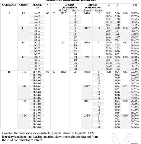
thickness varies from model to another. In each model the chord axial utilization (U% = actual axial load/ chord axial capacity) at the fixed end is also extracted to study its effect. All the parameters mentioned above are shown in table 2 below.
Figure 8 Boundary conditions for the K FEM
Table 2 FEM variables and parameters
CATEGORY GROUP MODEL ID
θ Φ CHORD
DIMENSIONS
BRACE DIMENSIONS
U %
do (mm) to(mm) db (mm) tb(mm)
I I-A I-A-01 60 60 246.5 4 167.8 12 30.81 3.00 0.68 89.17%
I-A-02 6 20.54 2.00 92.82%
I-A-03 8 15.41 1.50 95.34%
I-A-04 10 12.33 1.20 90.64%
I-A-05 12 10.27 1.00 84.82%
I-B I-B-01 4 187.7 10 30.81 2.50 0.76 92.29%
I-B-02 6 20.54 1.67 96.11%
I-B-03 8 15.41 1.25 97.65%
I-B-04 10 12.33 1.00 90.78%
I-B-05 12 10.27 0.83 85.07%
I-C I-C-01 200 3.3 163.8 8 30.30 2.42 0.82 91.85%
I-C-02 4.9 20.41 1.63 96.34%
I-C-03 6.5 15.38 1.23 98.64%
I-C-04 8.2 12.20 0.98 93.42%
I-C-05 9.8 10.20 0.82 87.47%
I-D I-D-01 3.3 126 10 30.30 3.03 0.63 90.58%
I-D-02 4.9 20.41 2.04 94.68%
I-D-03 6.5 15.38 1.54 94.09%
I-D-04 8.2 12.20 1.22 86.94%
I-D-05 9.8 10.20 1.02 82.38%
II II-A II-A-01 60 60 261.5 25 165.8 6 5.23 0.24 0.63 23.26%
II-A-02 8 0.32 32.23%
II-A-03 10 0.40 41.46%
II-A-04 12 0.48 50.53%
II-A-05 14 0.56 60.02%
II-B II-B-01 187.7 6 0.24 0.72 25.13%
II-B-02 8 0.32 34.51%
II-B-03 10 0.40 44.61%
II-B-04 12 0.48 54.55%
II-B-05 14 0.56 65.45%
II-C II-C-01 209.1 6 0.24 0.80 26.70%
II-C-02 8 0.32 36.70%
II-C-03 10 0.40 47.06%
II-C-04 12 0.48 57.99%
II-C-05 14 0.56 69.22%
II-D II-D-01 234.5 6 0.24 0.90 29.00%
II-D-02 8 0.32 39.60%
II-D-03 10 0.40 50.72%
II-D-04 12 0.48 62.30%
II-D-05 14 0.56 74.24%
Based on the parameters shown in table 2, and illustrated in Figure10. FEM boundary conditions and loading described above the results are obtained from the FEM and tabulated in table 3.
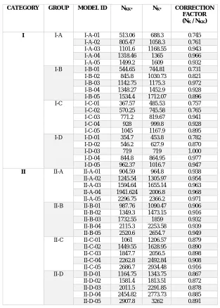
Table 3 FEM results
CATEGORY GROUP MODEL ID NKK* NK* CORRECTION
FACTOR (NK / NKK)
I I-A I-A-01 513.06 688.3 0.745
I-A-02 805.47 1058.3 0.761
I-A-03 1101.6 1168.55 0.943
I-A-04 1318.46 1365 0.966
I-A-05 1499.2 1609 0.932
I-B I-B-01 544.65 744.81 0.731
I-B-02 845.8 1030.73 0.821
I-B-03 1142.75 1175.3 0.972
I-B-04 1348.27 1452.9 0.928
I-B-05 1534.4 1712.07 0.896
I-C I-C-01 367.57 485.53 0.757
I-C-02 570.25 745.58 0.765
I-C-03 771.2 819.67 0.941
I-C-04 928 999.8 0.928
I-C-05 1045 1167.9 0.895
I-D I-D-01 354.7 453.8 0.782
I-D-02 546.2 627.9 0.870
I-D-03 719 719 1.000
I-D-04 844.8 864.95 0.977
I-D-05 962.37 1016.7 0.947
II II-A II-A-01 904.59 964.8 0.938
II-A-02 1245.54 1305.97 0.954 II-A-03 1594.64 1655.14 0.963 II-A-04 1941.624 2006.8 0.968 II-A-05 2296.75 2366.2 0.971
II-B II-B-01 987.76 1090.47 0.906
II-B-02 1349.3 1473.15 0.916
II-B-03 1732.55 1859 0.932
II-B-04 2115.3 2253.58 0.939
II-B-05 2520.6 2654.7 0.949
II-C II-C-01 1061 1206.57 0.879
II-C-02 1449.55 1628.95 0.890
II-C-03 1847.7 2056.5 0.898
II-C-04 2262.8 2492.84 0.908 II-C-05 2686.7 2934.48 0.916 II-D II-D-01 1164.75 1343.75 0.867 II-D-02 1581.4 1813.51 0.872 II-D-03 2011.5 2291.85 0.878 II-D-04 2454.82 2773.73 0.885
II-D-05 2907.8 3262 0.891
V. DISCUSSIONS
a. K-joints with overlap from CIDECT point of view:
The capacity of overlapped circular hollow k-joints are governed by the following criteria as stated by CIDECT a) Local yielding of the overlapping brace.
b) Local chord member yielding. c) Brace shear.
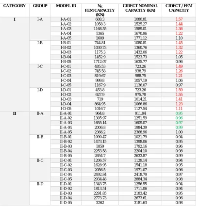
CIDECT provides equations to calculate the above mentioned limit states but these equations are limited to range of validity. The nominal capacity of the CHS K joint obtained from the FEM are compared with that obtained by substituting in the CIDECT equations in table 4:
Table 4 CIDECT AND FEM RESULTS FOR K-JOINTS
CATEGORY GROUP MODEL ID NK
FEM CAPACITY (KN)
CIDECT NOMINAL CAPACITY (KN)
CIDECT / FEM CAPACITY
I I-A I-A-01 688.3 1080.81 1.57
I-A-02 1058.3 1525.27 1.44
I-A-03 1168.55 1589.01 1.36
I-A-04 1365 1670.96 1.22
I-A-05 1609 1771.12 1.10
I-B I-B-01 744.81 1080.81 1.45
I-B-02 1030.73 1360.76 1.32
I-B-03 1175.3 1432.06 1.22
I-B-04 1452.9 1523.73 1.05
I-B-05 1712.07 1635.77 0.96
I-C I-C-01 485.53 723.26 1.49
I-C-02 745.58 938.79 1.26
I-C-03 819.67 988.75 1.21
I-C-04 999.8 1057.19 1.06
I-C-05 1167.9 1136.07 0.97
I-D I-D-01 453.8 723.26 1.59
I-D-02 627.9 975.78 1.55
I-D-03 719 1014.21 1.41
I-D-04 864.95 1066.86 1.23
I-D-05 1016.7 1127.54 1.11
II II-A II-A-01 964.8 911.94 0.95
II-A-02 1305.97 1251.59 0.96
II-A-03 1655.14 1609.07 0.97
II-A-04 2006.8 1984.39 0.99
II-A-05 2366.2 2368.96 1.00
II-B II-B-01 1090.47 1021.79 0.94
II-B-02 1473.15 1398.06 0.95
II-B-03 1859 1792.16 0.96
II-B-04 2253.58 2204.10 0.98
II-B-05 2654.7 2633.87 0.99
II-C II-C-01 1206.57 1129.14 0.94
II-C-02 1628.95 1541.18 0.95
II-C-03 2056.5 1971.07 0.96
II-C-04 2492.84 2418.79 0.97
II-C-05 2934.48 2884.34 0.98
II-D II-D-01 1343.75 1256.55 0.94
II-D-02 1813.51 1711.06 0.94
II-D-03 2291.85 2183.42 0.95
II-D-04 2773.73 2673.61 0.96
Table 4 shows that the capacity for the joints in category II obtained from CIDECT equations is less than or equal that obtained from the FEM. However, in category I the models which are within the CIDECT validity range, the joint capacity obtained from CIDECT reached 1.1 that obtained from the FEM.
For models with ID (A-01, A-02, A-03, A-04, B-01, B-02, B-03, C-01, C-02, C-03, D-01, D-02, I-D-03, I-D-04 and I-D-05), there is a large difference between the capacity obtained from FEM and the CIDECT equations because the parametric dimensions of these models are out of the validity range provided by the CIDECT. Despite that the overlapping percentage for models with ID (II-A-01, II-A-02, II-A-03, II-A-04 and II-A-05) equals to 21% which is out of the validity range provided by CIDECT, the nominal capacity obtained from FEM is close to that obtained from CIDECT equations.
The rest of the models which are within the validity range stated by CIDECT show that there is compatibility between the capacity obtained from the FEM and from that obtained from CIDECT equations. As the CIDECT ultimate capacity ranges from 0.94 to 1.1 the FEM ultimate capacity.
All the models which are within the validity range stated by CIDECT are governed by local yielding of the overlapping brace.
Also the models with ID (II-A-01, II-A-02, II-A-03, II-A-04 and I-A-05) which have overlapping percentage (21%) which is out of the validity were governed by local yielding of the overlapping brace.
Local chord member yielding was governing models with ID (I-A-01, I-B-01, I-C-01 and I-D-01) but these models were out of the CIDECT validity range.
None of the joints studied in this research was governed by Brace shear limit state.
b. Failure modes and joint behaviour
The modes of failure for overlapping CHS K-joints, are either brace local buckling (BLB), or chord bending (CB) or a combination of both. The joint deformation shape at the ultimate load is used to determine the mode of failure that is governing the jointthat was mentioned by E.M. Dexter and M. M. Lee (1999).These are also the modes of failure that can occur in CHS KK joints and governing the capacity and they are also determined by the same approach that was followed by E.M. Dexter and M. M. Lee.
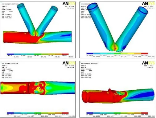
Category I
The FEM with ID (01 and 02) in category (I) failed by chord bending (CB) due to high values of (as ranges from 2 to 3.03 and ranges from 20.41 to 30.81 which indicates that the chord is more slender than that in the rest of the models of category (I). Because of these high values the failure takes place in the chord only without brace sharing. In other words, the brace is very compact when compared to the chord. The deformation shape is clarified in Figure 11.
While the FEM with ID (03, 04 and 05) in category (I) failed by a combination of brace local buckling and chord bending (BLB, CB) as ranges from 0.82 to 1.5 which indicates that the compactness of the brace to the chord decreased than that in the previous FEM in category (I). Which means that the joint capacity depends on both brace and chord
compactness. The corresponding deformed shape for this mode of failure shown in Figure12.
Category II
All the FEM in this category fail by brace local buckling (BLB) (as in Figure13) as the values of ( are very low which indicates the high compactness of the chord compared to the compactness of the brace that’s why chord bending (CB) don’t occur in the FEM of this category. The joint capacity depends on the brace compactness only without the chord sharing.
c. Parameters effect on the correction factor (C.F)
The parametric study results tabulated in table (3) are represented graphically in Fig (14, 15 and 16) to investigate the effect of different parameters while taking into consideration the effect of the corresponding chord axial utilization (U%) on the joint capacity which is discussed in the following parts:
Category I
For the FEM with ID (01 and 02) in category (I), as () increases C.F decreases. (Shown graphically in Fig14 and Fig 15). Because the failure mode governing these models is (CB) which depends mainly on the compactness of the chord. C.F in these models ranges from (0.73 to 0.87).
For the FEM with ID (03, 04 and 05) in category (I), as () increases C.F increases. The reason of that is that in these models the joint fails by combination of CB and BLB so as the chord becomes more slender the brace sharing in the joint capacity increases. For the same values of () C.F depends on the brace compactness, that’s why C.F of model I-A-03 is less than that of model I-D-03. C.F in these models ranges from (0.895 to 1) (shown graphically in Fig 14 and Figure15). As for the models in which the (BLB+CB) is the governing failure mode, C.F is inversely proportional with
Category II
BLB is the failure mode governing the FEM in this category which depends mainly on the brace compactness so as () increases the C.F increases at constant () (shown graphically in Fig 16). Brace compactness is the most effective parameter for the FEM in this category because these models fail by BLB as mentioned above. Therefore, for the same brace thickness as ( increases the brace compactness decreases with respect to the chord, and the C.F decreases and that is clear in Fig 16.
Figure 13 Deformed shape for the FEM with ID (03-04-05) in category I at the ultimate load Figure 12 Deformed shape for the FEM) in
d. Figures representing the parametric study results
Figure 14. Shows the results of the parametric study tabulated in table (3) in order to represent graphically the effect of the effect of the chord radius to thickness ratio (), while taking into consideration the effect of the corresponding chord axial utilization (U%) on
the joint capacity on the correction factor for different values of β for Category I
a) β=0.68
b) β=0.76
Figure 15. Shows the results of the parametric study tabulated in table (3) in order to represent graphically the effect of brace thickness to chord thickness ratio (), while taking into consideration the effect of the corresponding chord axial utilization (U%) on the joint capacity on the correction factor for different values of β for Category I.
a) β=0.68
d) β=0.63
c) β=0.82
Figure 16. Shows the results of the parametric study tabulated in table (3) in order to represent graphically the effect of brace thickness to chord thickness ratio (), while taking into consideration the effect of the corresponding chord axial
utilization (U%) on the joint capacity on the correction factor for different values of β for Category II.
a) β=0.63
b) β=0.72
c) β=0.8
d) β=0.9
Figure 16the effect of () and the corresponding (U %) on the correction factor for different values of β and constant
VI. CONCLUSION
Based on the results obtained from the parametric study and comparing the calibrated finite element models of CHS overlapped KK joints with the corresponding CHS overlapped K joints the following results were obtained:
1. The failure modes of CHS overlapped K joints are similar to the modes of failure in overlapped KK joint. Three failure modes may govern the CHS overlapped KK connections (chord bending or brace local buckling or combination between both of them), also it was clear that geometric parameters have a significant effect on the joint behavior and failure mode.
2. For high values of ( and which indicates that the braces are much compact relative to the chord, chord bending failure (CB) occurs, the difference between the K, KK joint capacity increases, and the correction factor (C.F) ranges from 0.730.87.
3. For medium values of ( and which indicates that the braces and the chord are sharing in the joint capacity, a combination of chord bending failure (CB) and the brace local buckling (BLB) failure occurs, the difference between the K, KK joint capacity decreases and the correction factor (C.F) ranges from 0.91 which is inversely proportional to
4. For low values of ( and which indicates that the braces are very slender relative to that of the chord, the chord doesn’t share in the joint capacity; so the brace local buckling (BLB) failure occurs, and the correction factor (C.F) ranges from 0.870.97 which is inversely proportional to
5. The correction factor, for the joints studied in this research which are within the validity range stated by CIDECT, ranges from 0.87 to 0.95. Thus, a correction factor of value equals to 0.90 can be utilized in calculating the capacity the CHS KK overlapped joint.
REFERENCES
[1] ANSYS program. Release 14 user’s manual, Swanson analysis system.
[2] Chen, Zhao and Chen, “Parametric analysis and design equation of ultimate capacity for unstiffened overlapped CHS K-joints”,Front. Archit. Civ. Eng. China, Vol. 2, pp. 107-115, 2008.
[3] Dexter and Lee, “Static strength of axially loaded tubular K-joints”, Journal of Structural Engineering, Vol. 125, pp.194-201, 1999
[4] Forti, Requena and Forti, “Parametric study of tubular KK multi-planar steel connections”, Journal of Constructional Steel Research, Vol. 114, pp.188–195, 2015
[5] Lee and Wilmshurst, “Numerical Modelling of CHS Joints with Multiplane Double-K Configuration”,J. Construct. Steel Research, Vol. 32, pp. 281-301, 1995
[6] Lee and Wilmshurst,“Parametric study of strength of tubular multi-planar KK-joints”,Journal of Structural Engineering, Vol. 122, pp. 893-904,1996
[7] Makino et al. “Ultimate capacity of tubular double K-joints”, In Proceedingsof 2nd International Institute of Welding Conference on Welding of TubularStructures. Boston, pp. 451-458,1984
[8] Zhao, Han, Hu, Chen and Wu,“Experimental study on static behavior of multi-planar overlapped CHSKK-joints”, In Proceedings of the 15th International Symposium on Tubular Structures, Rio de Janeiro, Brazil. Tubular structures XV, pp. 505-512,2015.