Function Based Systematic Design Approach
Incorporated With TRIZ Tools
Shiv Kumar1, P. S. Bajwa2, Kulbhushan3
P.G. Student, Department of Mechanical Engineering, L. R. Institute of Engg. & Technology, Solan (H. P.), India1
Asst. Professor, Department of Mechanical Engineering, L. R. Institute of Engg. & Technology, Solan (H. P.), India 2
Asst. Professor, Department of Mechanical Engineering, L. R. Institute of Engg. & Technology, Solan (H. P.), India 3
ABSTRACT: Innovative development in the design of product & manufacturing system often uses various technologies which involve the various techniques and methodologies to improve the productivity. This paper describe methodology which built a model, this model incorporates concept generator and FAST with TRIZ.
KEYWORDS: Concept generator, TRIZ, FAST, Value engineering.
I. INTRODUCTION
Vol. 7, Issue 2, February 2018
The creation of a concept generator is an iterative process. In an attempt to study relationships between a product, its components, and its sub-functions, different matrices were tested to determine. Each matrix that has been created, such as ones that relate parts to products, products to functions, functions to part, etc., has been checked to see if the relationship between the data was informative and that the data itself was in a useable format. Useable information means information that is formatted so that it can be manipulated with existing data structures, such as the product matrix from step five, to obtain a solution or answer to a question.
The concept generator is to be used at the conceptual design stage. The functional model from the customer needs is the input into the concept generator and product components are the output. The collection of design information raw data, the formation of the raw data into the concept generator, and finally the development of a way to use the concept generator. As stated above and as shown in Figure 1, the input into the concept generator is a functional model based on the customer needs. The outputs of the concept generator are components that solve some or all of the sub-functions from the product’s functional model.
Fig1. Concept Generator Flow Chart
The concept generator is the functional model from the customer needs of a design project. The functional model is used to obtain suggested components for a design. The functional model is created for the new product design. The procedure is the same one that appears in Stone and Wood’s paper, “Development of a Functional Basis for Design” [4]. In addition to the functional model, a product matrix for the new product is created also using the method
.
II. RELATEDWORK
2.1Methodology
In accordance with TRIZ applications, the advantages and imperfections can be concluded as follows: Advantage
Systematic process to resolve problems.
More effective and efficient solutions obtained by fewer efforts.
The adaptability to integrate with other methodologies to resolve much complicated and difficult problems.
Imperfections
The subjective judgments of problem-solving process. For the purpose of the accomplishment of more and more complicated construction projects, TRIZ is applied and modified in this chapter. In addition, its defects will be refined through other useful methodologies. And, this systematic innovation model will be developed by the following concept along with a simple example of constructional elements. The following is the concept diagram.
Concept
Generator
Functional Model
Fig. 2 The concept of systematic innovation model.
Briefly speaking, to integrate TRIZ with other methodologies and the concept of VE is the core of this study. In accordance with Figure 2, this systematic innovation model will be divided into four steps as the sections afterwards. The following paragraphs delineate brief contents of these sections
2.2FAST Analysis
The advanced VE/TRIZ method that are suggested are basically a combination of the work of three contributors to creativity and problem solving: Lawrence Miles, enrich Altshuller and Alex Osborne. Below figure 3 shows the basic idea of how the triz tools or inventive principles are used together with FAST diagrams for building a n efficient functional model.
Fig. 3 Incorporation of VE/ TRIZ methodology
Step 1 - Basic Fast Diagram
Begin the Value Management process in the usual manner with a Pre-Event to define the problem to be solved, establish the appraise of success and obtain management support and obligation
Continue with the Value Management process by building the FAST diagram as shown in figure 4.
After the FAST diagram is completed, construct a functional model of the major logic path in the FAST diagram. This model is built much like a classic FAST diagram except that functions can be either useful or harmful, corresponding to the definition of Ideality. The functional model deconstructs a problem by creating a functional
Lawerence Miles
•Fast Diagramme
Generic Altshuller
•Inventive Principle
Alex Osbourne
Vol. 7, Issue 2, February 2018
diagram that relates the useful and harmful factors in the system. Unlike a FAST diagram, the modified functional model can include objects, system, actions, parameters and conditions as well as functions.
Fig. 4 Basic FAST Diagram
The arrows connecting the factors describe their relationship. A solid arrow means that the first factor produces the second factor.
TRIZ inventive principles can be used to generate ideas for improvement. This is typically done in a brainstorming session based on the principles of Osborne. Whenever a group is brainstorming a problem or issue, the users face a significant problem of psychological inertia. Alex Osborne developed brainstorming techniques to help overcome the psychological inertia people face when attempting to conceive creative problem solutions. Psychological inertia results because our human experience is limited and we tend to think of a problem solution that is similar to problem solutions that we have previously experienced. Participants in a brainstorming session can work together to break down psychological inertia based on the breadth of their collective experiences but it can never be eliminated. Because TRIZ is built on such a broad knowledgebase, it can dramatically reduce psychological inertia and develop a nearly exhaustive set of abstract solutions. The abstract solutions must then be applied to the real world problem to create a problem specific solution opportunity. Because the major logic path functional model is a nearly pure functional model (i.e. it does not reflect the components of the system in any level of significant detail, it tends to generatenewproduct concepts. Improving useful functions at this point often means generating completely new product conceptstional model (i.e. it does not reflect the components of the system in any level of significant detail, it tends to generatenewproduct concepts. Improving useful functions at this point often means generating completely new product concepts.
Step 2 – Incorporating Design Elements into the Functional Model
Next, we take a departure from traditional FAST models. We can add the physical components of the system as objects in the model. The concept here is that an object can produce function.
The functional model of the major logic path with the physical components added can now be analysed to identify opportunities to improve the useful functions in the model and toimprove the usefulness of the system components. Here we have the opportunity for improvement of useful functions as well as the opportunity to improve the system components. Improvementstothecomponentscould be additional functionality and/or cost improvements.
TRIZ inventive principles can be used again to generate ideas to improve the usefulness of functions and components in the functional model of the major logic path with the physical components added.
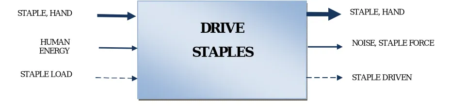
With the better quality product selected, the reverse engineering portion of the comparison begins. The first step is to gather the weighted customer needs for the product pair. This involves interviewing people who would be likely users of the products, finding out what theirs wants and needs are for the two products and how strongly they feel about them. How strongly they feel about each want or need is the weighting of each customer need and generally has values ranging from one to five. A five would correspond with a “must” and a one could mean that the need was passively mentioned during the interview. After the customer needs have been gathered, a black box model is created. The black box model states the overall function of the product and identifies all flows in and out of the product. An example of a black box model can be seen in Figure 5 below. The heavy arrows represent material flows, the regular arrows represent energy flows, and the dashed arrows represent signal flows. Material flows can be any liquid, solid or gas flowing in and out of the system. In the example below the staple and hand are the material flows. Energy flows can be electrical, pneumatic, mechanical, etc. Human energy is the energy flow in the example below. A signal is any type of
Import Solid Secure Solid Transmit Force Export Solid Solid
visual, audio, vibration, etc. that can be picked up by human senses for example. In the case of the staple gun example below, the user would visually see that the staples are in the gun and thus loaded.
Fig. 5. Staple Gun Black Box Model
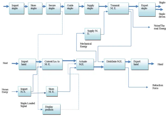
After the black box model is created for the product pair, a functional model is made. The functional model is created using a language defined in Stone and Wood’s paper “Development of a Functional Basis for Design” [4]. Using the black box model, each flow is followed through the product. Each function that the product performs on each flow is listed in verb-object format similar to that in the black box. The operation is the verb and the flow is the object. An example of a functional model for the staple gun can be seen in Figure 6 below. With the function model, or function structure, finished, a product vector can now be made. Listing all of the sub-functions from the functional model and summing up each customer need weight associated with that function, results in the product vector. An example of a product vector for the staple gun is shown in table 1 below. The customer needs are listed with their weight and associated flows below the product vector. The list of each customer need weight appears as well as the total of all the weights for each sub-function.
Table 1 Judgemental Matrix 1
Customer Needs Rank Flow
Customer Needs Rank Flow Customer Needs Rank Flow
Drive staples 5 Staple Easy actuation 4 Hand Durable material 4 M.E. Use different size staples 3 Staple Comfortable handle 3 Hand Make staples flush 4 Staple Light weight 3 H.E. Easy to load 3 H.E. Safe to use 3 Hand Minimize recoil 3 H.E.
DRIVE
STAPLES
STAPLE, HAND
HUMAN ENERGY STAPLE LOAD
STAPLE, HAND
NOISE, STAPLE FORCE
Vol. 7, Issue 2, February 2018
Fig 6. Staple Gun Functional Model
2.3 TRIZ Tools
Having justified the parts, the functional model is revisited. Double checking the functional model makes certain that the sub-functions are defined properly and that all flows are accounted for. The functional models are corrected if need be. Lastly, the functional models are examined to determine if the minimum number of sub functions was achieved. Once the functional model is set, a Function-Component matrix can be made. A Function-Component matrix maps a product’s parts to it functional model’s sub-functions.
TraditionalTRIZtoolssuchas“SufieldAnalysis,”arenotobjectivesufficienttoinfluenceotherspecialistswhentransitingspecific problems into general ones. Despite the functional tools of TRIZ, some references suggest replacing them withAHP and GRA in order to increase the objectivity of defining problems and choosing the most appropriate engineering parameters. Moreover, the advantages fromAHP can be briefly listed below. [5, 6,7,8]
Higher objectivity
Systematic and logical process to define and organize tough problems
The gradual steps to break down main system problems for subsequent analysis Objective analysis of the importance of each in depth problems
Import staple
Store staple
Secure staple
Guide staple
Supply staple
Transmit M. E.
Export staple
Staple driven Staple Staple
Supply M. E.
Noise/Tha-rmal Energy
Import hand
Convert h.e. to M. E.
Actuate M.E.
Distribute M.E. Export hand Mechanical
Energy
Hand
Hand
Import H. E.
Store M. E.
Human Energy
Display position
Retraction Force
Step 4: This stage illustrated with describes how to decompose the main problem of the system into several requirement indices and to determine their correspondent weights. According to the definition of the technical contradiction, it is trying to improve a feature/parameter that may result in a contradiction. In one word, the improving parameter is obtained before the worsening one. First, managers/engineers should identify the macro problems of the system by questionnaires, brainstorming, or other method. Second, these main problems are decomposed into sub-problems and further into requirement indices. This step is achieved by questioning external specialists, internal managers, senior engineers, or even the first-line workers, which is the assumption of this study. [ 9,10,11]
Table2. Staple Gun Function- Contradiction Matrix
Im p o rt S ta p le S to re S ta p le S e c u re S ta p le G u id e S ta p le T ra n sm it M . E . E x p o rt S ta p le Im p o rt H a n d Co n v e rt H .E . to M .E . A c tu a te M .E . S u p p ly M .E . D is tri b u te M .E . E x p o rt H a n d Im p o rt H .E . S to re M .E . D is p la y P o si ti o n
Handle 0 0 0 0 0 0 2 2 2 0 2 2 2 0 0
Inner Handle Plate 0 0 0 0 0 0 0 0 1 0 1 0 1 0 0 Outer Handle Plate 0 0 0 0 0 0 1 0 1 0 1 1 0 0 0
Cover 0 0 0 0 0 0 0 0 0 0 2 0 0 0 2
Torsion Spring 0 0 0 0 0 0 0 0 0 0 0 2 0 0 0
Spring Support 0 0 0 0 1 1 0 1 0 1 0 0 0 1 0
Steel plate (Staple) 0 0 0 0 2 2 0 0 0 1 0 0 0 0 0 Coil Spring (comp.) 0 0 0 0 1 1 0 1 0 1 0 0 0 1 0
Large Leaf Spring 0 0 0 0 1 1 0 1 0 1 0 0 0 1 0
Spring Guide 0 0 0 0 0 0 0 1 0 1 0 0 0 1 0
Lock Plate 2 2 2 1 0 0 0 0 0 0 0 0 0 0 0
Push Plate 2 2 2 2 0 0 0 0 0 0 0 0 0 0 0
Staple Tray 2 2 2 2 0 0 0 0 0 0 0 0 0 0 0
Catch Plate 0 0 0 0 0 0 0 2 2 0 2 0 2 2 0
Rocker Arm 0 0 0 0 0 0 0 1 1 0 1 0 1 1 0
Step 5: Input the improving and worsening parameters: In reference to preceding section, individually highlight the improving and worsening parameters in the rows (improving ones) and columns (worsening ones) of the updated contradiction matrix as shown in table 2.
Vol. 7, Issue 2, February 2018
Step 6The input into the concept generator is the functional model from the customer needs of a design project. The functional model issued to obtain suggested components for a design. The functional model is created for the new product design Now that the better product has been determined from comparing the internals of each product as well as the overall performance, we check to see if the product selected in step eight is the same as the product selected from step one. If the decision from step one was thorough, the two products should be the same. If the products are different, the decisions from step one and step eight need to be re-examined to make sure something was not overlooked. In mostcases, however, the products selected will be the same. Judgmental Matrix for the Staple Gun Functional Model shown in table 3 below.
Table 3.Judgemental matrix Import Staple 1
Store Staple 1 Secure Staple 1 Guide Staple 1 Transmit M.E. 1 Export Staple 1 Import hand 1 Convert H.E. to M.E. 1 Actuate M.E. 1 Supply M.E. 0 Distribute M.E. 1 Export H.E. 0 Import H.E. 0 Store M.E. 0 Display position 0
Develop the “Judgmental Matrix.” Before defining objective weights of each requirement indices, managers/ engineers have to develop the “Judgmental Matrix” first
Table 4 Pair-wise comparison scale. [11]
It is a square matrix of size n × n and composed by pair-wise comparisons about the extent of the importance of each index with the relative scale measurement shown in Table 4, a questionnaire of pair-wise comparisons towards the same relative people mentioned in Step 1 is used as well
2.4 Evaluation Stage
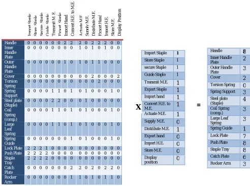
Now that, containing new design information with respect to the Function Component matrix has been created, it can be multiplied with the Function-Component matrix to obtain suggested components for the new design. And theyare multiplied which is shown in table 5 below. A vector with the same number of rows as the function component matrix is obtained.
Numerical Rating Verbal judgements of preferences
Table 5. Multiplication of Matrices
Step 7. Evaluate the technical, economical, and other feasibility: After the tests, at least one gathering should be hold for the effectiveness evaluation of this alternative and its tiny corrections, which can be analysed through meetings or the famous brainstorming method, “Delphi method.” Steps for Delphi method are described below:
i. Elucidate the subject and task to the analysis team
ii. Develop the first round Delphi questionnaire. (Team members are questioned separately.) iii. Analyse and reduce the first round responses.
iv. Prepare the second round Delphi questionnaire.
v. Analyse and reduce the second round responses. (Steps iii to v are repeated as long as desired or necessary to achieve stability in the results.)
vi. Construct the conclusion by the analysis team
The final step of the comparative analysis is to take all of the information gathered for the two products and format the data so that design principles can be obtained. One way to try and pull design principles from the two designs is two
Import Staple 1
Store Staple 1 secure Staple 1 Guide Staple 1 Transmit M.E. 1 Export Staple 1 Import hand 1 Convert H.E. to M.E. 1 Actuate M.E. 1 Supply M.E. 0 Distribute M.E. 1 Export hand 0 Import H.E. 0 Store M.E. 0 Display
position 0
Im p o rt S ta p le S to re S ta p le S e c u re S ta p le G u id e S ta p le T ra n sm it M . E . E x p o rt S ta p le Im p o rt H a n d Co n v e rt H .E . to M .E . A c tu a te M .E . S u p p ly M .E . D is tri b u te M .E . E x p o rt H a n d Im p o rt H .E . S to re M .E . D is p la y P o si ti o n
Handle 0 0 0 0 0 0 2 2 2 0 2 2 2 0 0
Inner Handle Plate
0 0 0 0 0 0 0 0 1 0 1 0 1 0 0
Outer Handle Plate
0 0 0 0 0 0 1 0 1 0 1 1 0 0 0
Cover 0 0 0 0 0 0 0 0 0 0 2 0 0 0 2
Torsion Spring
0 0 0 0 0 0 0 0 0 0 0 2 0 0 0
Spring Support
0 0 0 0 1 1 0 1 0 1 0 0 0 1 0
Steel plate (Staple)
0 0 0 0 2 2 0 0 0 1 0 0 0 0 0
Coil Spring (comp.)
0 0 0 0 1 1 0 1 0 1 0 0 0 1 0
Large Leaf Spring
0 0 0 0 1 1 0 1 0 1 0 0 0 1 0
Spring Guide
0 0 0 0 0 0 0 1 0 1 0 0 0 1 0
Lock Plate 2 2 2 1 0 0 0 0 0 0 0 0 0 0 0
Push Plate 2 2 2 2 0 0 0 0 0 0 0 0 0 0 0
Staple Tray
2 2 2 2 0 0 0 0 0 0 0 0 0 0 0
Catch Plate
0 0 0 0 0 0 0 2 2 0 2 0 2 2 0
Rocker Arm
0 0 0 0 0 0 0 1 1 0 1 0 1 1 0
X
=
Handle 8 Inner Handle Plate 2 Outer Handle Plate 3 Cover 2 Torsion Spring 0 Spring Support 3 Steel plate
(Staple) 4 Coil Spring (comp.) 3 Large Leaf
Vol. 7, Issue 2, February 2018
create an action matrix. The action matrix lists the sub-functions for the two products in the first column. The second and fourth columns contain the solution each product has for a given sub-function. For each sub-function, a given product could perform better, worse, or the same as the other product. The third column, in-between the two products, is the action taken column. An action exists only if one product’s solution for a sub function is different than the other product’s solution. The action taken is an explanation of the design difference. Essentially the action could be applied to the inferior solution to get to the better solution. The list of actions represents design changes that would have been made in an iterative design process. As stated earlier, by examining the design iteration changes, we can learn ways of applying that knowledge to a design the first time 24 and reduce design iterations.
Record Keeping. In order for the empirical study to effective, the data needs to be recorded in a repeatable, accessible manor. If no person can repeat the results obtained, or if no one could access the information collected, the empirical study would have no value. Stone, at the University of Missouri – Rolla’s Basic Engineering Department, is recording product data for a repository database to be referenced in the future by academic and industrial communities. A team of graduate students input the product information into the database. For that reason Stone has created a standard format for the data so that each student enters the data in the same fashion. If the information were not of the same format, the accessing the repository would not be effective. For example, if a designer wanted to reference functional model information 25 for their design with the functional model information in the database to perform the Design by Analogy procedure described earlier, the designer would want all of the functional models to be formatted the same. For that matter, each piece of product information for each product must be entered at the same location and the in the same format as every other product. Since Stone’s technique for data collecting works for the repository of products, the technique was adapted for use with the small database developed from the empirical study. The format consists of having nine folders for each product, a folder for every different type of information collected. Also a design notebook is kept to supplement the formatted data with notes
Step 8. This stage of the design principle involves checking the suggested components with the design concept generated after a designer checks their functional model against whichever Function Component matrices a total list of suggested components is compiled. This list could have components from one or more products. The designer then needed to check to see which components from that list meet the needs of the design constraints generated. Some suggested components may perform the same sub-functions; therefore the designer needs to select the component that most closely fits their design concept. By using both the design principles and the Function-Component matrices, a designer can greatly reduce design iterations. Make a decision: Following the composite evaluation of feasibility, innovation team could judge the effectiveness of the tentative solution by pre-set criteria (requirement indices or others). Fortunately, if the tentative solution meets the criteria, it will be regarded as final solution. On the contrary, if this alternative cannot meet the pre-set criteria, it is abandoned and replaced with other tentative solution developed again. If two or three specific solutions were rejected as well, it might be essential to re-assess the improving and worsening parameters. In other words, it might make the process of problem solving
Step 9. Create the output: After the tentative specific solution meets the pre-set criteria eventually, it is taken as the final answer to practical situation or projects of larger scale. In addition, the process of solving this problem will be documented and recorded in the knowledge base for management
III.DISCUSSION
One empirical study suggests that while actual ideas recorded may in fact have decreased, the ideas were more complete, better formulated and a higher percentage were evaluated as potentially valuable. The result was a significant net positive impact on the ratio of good ideas to the overall number of ideas generated in the brainstorming session. A majority of workshops conducted using the TRIZ Enhanced Brainstorming approach have reported that between 25% and 40% additional ideas were generated as a direct result of the application of the TRIZ methodology. In comparison
with traditional process of solving problems, this theory ―TRIZtransforms specific problems into generic ones
The methodology ―Quality Function Deployment (QFD) may be the better answer to link the gap between requirements and managers/engineers. The classical TRIZ doesn‘t offer an effective and efficient way to clear the key-point in the whole problem. Importing the QFD can improve this disadvantage of TRIZ by gathering all relevant information about the customers ‘wishes through surveys, interviews, tests, benchmarks, etc.
Moreover, the scores of the engineering features/parameters created from the ―House of Qualityof QFD can express the importance of each parameter of the problem. [20, 21, 22]In other words, the primary function of QFD is to identify the most important issues and parameters of the products and to link priorities and target values back to the customer.[20, 21, 22, 23, 24]
IV.CONCLUSION
TRIZ and Value Management can be incorporatein the course of FAST diagrams and concept generator. Value Management relies on a variety of brainstorming techniques to produce dilemma solutions. The cost-effective significance of the development, for sure, depends ahead identifying a ground-breaking, elevated assessment clarification. For the most part, brainstorming technique used in Value Management is psychosomatic in character and weighed down by psychosomatic sluggishness which tends to limit the number and quality of thoughts. TRIZ in contrast, isa scientifically based problem solving methodology driven by a widespread awareness. Concept generator can generate a large set of prospective solutions that are exceedingly inventive. The mixture of concept generator with TRIZ offers a prospective tocategorize higher value solutions more swiftly than eithertechnique alone. This model leads to opportunities both forproduct improvements and cost reductions by utilizing theTRIZ inventive principles with concept generator. Concept generator with the TRIZ principals involve the multiplication of contradiction matrix and judgemental matrix and built a component matrix and the purpose of this model is to breed ideas to advance the efficiency of functions and components in the well-designed function model and in unison, also examine thoughts to diminish or reduce detrimental functions.
REFERENCES
[1] G. Altshuller (H. Altov), English translation by Lev Shulyak, "And Suddenly the Inventor Appeared: TRIZ, the Theory of Inventive Problem, Technical Innovation Center, Inc., USA (1994)
[2] GenrichAltshuller, English translation by Anthony Williams "Creativity as an Exact Science", American Supplier Institute, 1988. [3] The TRIZ Journalhttp://www.triz-journal.com/
[4] Stone, Robert B., and Kristin L. Wood, “Development of a Functional Basis for Design,” Proc. ASME Design Theory and Methodology Conference, DETC99/DTM-8765, 1999.
[5] Min-Chieh Chang, “The Improvement of TRIZ Method and the Application,” Department of Industrial Engineering and Management, Huafan University, 2004.
[6] Janice Marconi, “ARIZ: The Algorithm for Inventive Problem Solving–An Americanized Learning Framework,” http://www.trizjournal.com/, 1998.
[7] Boris Zlotin and AllaZusman, “ARIZ on the Move,” http://www.trizjournal.com/, 1999.
[8] Chih-Chen Liu, “A Study of TRIZ Method Improvements and EcoInnovative Design Methods,” Department of Mechanical Engineering,National Cheng Kung University
[9] Jahau Lewis Chen and Chih-Chen Liu, “A TRIZ Inventive Design Method without Contradiction
Information,”http://www.trizjournal.com/, 2001.
[10] Sy-JyeGuo and R. L. Tucker, “Automation Needs Determination Using AHP Approach,” University of Texas at Austin, 1993
[11] Miroslaw J. Skibniewski and Li-Chung Chao, “Evaluation of Advanced Construction Technology with AHP Method,” Journal of ConstructionEngineering and Management, 1992.
[12] Darrell Mann, Simon Dewulf, Boris Zlotin, andAllaZusman, “Matrix 2003: Updating the TRIZ Contradiction Matrix,” CREAX Press, 2003.
[13] Chii-Horng Lu, ―The Multi-Function Coin Mechanism Design with TRIZ‖, Department of Mechanical and Electro-Mechanical Engineering, NationalSun Yat-Sen University, 2000
[14] Hsiang-Tang Chang, ―The Study of Eco-Innovative Design Integrating TRIZwith Extension Method,‖ Department of Mechanical
Engineering,
NationalCheng Kung University, Taiwan, 2004.
[15] A Yen-Chang Chu, ―A Study on Integrating TRIZ Method with FunctionalAnalysis‖, Department of Mechanical Engineering, National
Cheng
Vol. 7, Issue 2, February 2018
[16] Mei-Hsiu Lin, ―Application of TRIZ Principle in Case Study of a Paten development‖, Department of Mechanical Engineering, Chung
Yuan University, 2004
[17] Yung-Jin Shiau, ―Brief Introduction to the Inventing Theory - TRIZ‖, http://www.flotrend.com.tw, 2002.
[18] R. Stratton and D. Mann, ―Systematic Innovation & the UnderlyingPrinciples behind TRIZ & TOC‖, Journal of Materials Processing
Technology,2003.
[19] Yao-Jen Fan, ―The Integrated TRIZ Method and the Applications, Department of Mechanical Engineering, National Cheng Kung
University, Taiwan, 2001.
[20] Noel León-Rovira and Ing. Humberto Aguayo,A New Model of the Conceptual Design Process Using QFD/FA/TRIZ,‖http://www.trizjournal.com/, 1998.
[21] Eve M. Burke, ―Quality Function Deployment from an Operations ResearchPerspective,‖ the Graduate School of Engineering of the Air
Force
Institute of Technology, 1999.
[22] Neil Eldin and VerdaHikle, ―Pilot Study of Quality Function Deployment inConstruction Projects,‖ Journal of Construction Engineering
andManagement, 2003.
[23] J. M. Kamara and C. J. Anumba, ―Client Requirements Processing inConstruction: A New Approach Using QFD,‖ Journal of
![Table 4 Pair-wise comparison scale. [11]](https://thumb-us.123doks.com/thumbv2/123dok_us/1578002.1194207/8.595.166.429.600.662/table-pair-wise-comparison-scale.webp)