The Effect of Impeller Width on the Location
of BEP in a Centrifugal Pump
Vinayak Manur 1, Sharanabasappa 2, M. S. Hebbal 3
P.G.Students, Department of Mechanical Engineering, Basaveshwar Engineering College, Bagalkot, Karnataka, India 12
Faculty, Department of Mechanical Engineering, Basaveshwar Engineering College, Bagalkot, Karnataka, India3
ABSTRACT: The flow rate at Best Efficiency Point (BEP) of a centrifugal pump is governed by the geometry of the impeller and volute/diffuser. The impeller width at the outlet and the throat area of volute are known to be the prominent factor which effect most the location of the BEP. There are different procedures proposed by various researchers to design the impeller and the volute casing for the specified duty parameters. Most of them are empirical relations based on the experience gained in earlier design. The procedures suggested are good enough to begin with determination various primary dimensions of both impeller and volute/diffuser, but the flow rate and head developed at BEP are found to be considerably away from the desired location. The design using CFD computer programmes provide practically acceptable results and the deviations are negligible. Based on the results obtained by CFD analysis it is observed that the BEP shifts towards right side as the impeller width increases. Pump head reduces with the increase in impeller width for the given mass flow rate.
KEYWORDS
:
Impeller outlet width, CFD, BEPI.INTRODUCTION
The performance of the centrifugal pumps can be improved by reducing the various losses due to shock at entry & exit, flow separation, stalling, recirculation, friction and mechanical losses etc. The geometric parameters such as inlet blade angle, outlet blade angle, number of blades, impeller outlet width and volute throat area are the major contributing factors governing the flow at Best Efficiency Point (BEP) of the centrifugal pump. The pumps with better efficiency reduce the ecological burden on nature. Therefore it is essential to design pumps with highest efficiency possible using the modern tools available for design of hydraulic components of the pumps like impeller and volute casing or diffusers. Here an effort is made to make use of the modern tool Computational Fluid Dynamics (CFD) to design and analyse the effect of impeller width on the location of BEP and efficiency of the pump.
II.LITERATUREREVIEW
volute design, impeller design and flow analysis: It is observed that a lesser number of investigations were undertaken to study the variation of impeller width on the pump performance. In this view an attempt is made to study the variation of impeller width on the location of BEP and hydraulic efficiency of the centrifugal pump.
III.MODELLING OF CENTRIFUGAL PUMP HYDRAULIC PASSAGE
3.1 Three dimensional and finite element modelling of centrifugal pump.
In order to carry out the flow analysis through impeller and volute casing of a centrifugal pump, it is essential to have geometric model of the pump. To determine the various dimensions of the impeller and volute casing, certain basic inputs are essential and they are specified in Table 3.1.
Table 3.1 Input parameters
Parameters Values
Head (H) 100 m Mass Flow rate (Q) 210 m3/hr Speed (N) 3000 rpm
Density of water (ρ) 1000 kg/m3
Vane outlet angle (β2) 250
No. of vanes (Z) 6 The specific speed (Ns) of the pump is calculated using equation (1)
N Q N =s
3/4
H (1) The specific speed of a centrifugal pump with the duty parameters given in Table 3.1 is 1183 min-1.
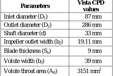
The impeller and volute casing dimensions calculated from ANSYS Vista CPD (Centrifugal Pump Deign) are given in Table 3.2
Table 3.2 Impeller and Volute Parameters from Vista CPD
Parameters Vista CPD
values
Inlet diameter (D1) 87 mm
Outlet diameter (D2) 286 mm
Shaft diameter (d) 33 mm Impeller outlet width (b2) 19.11 mm
Blade thickness (Su) 9 mm
Volute width (b3) 39 mm
Volute throat area (A8) 3151 mm2
Meshing of the impeller model is carried out using ANSYS TurboGrid and the volute casing model is meshed using the Meshing module available in ANSYS. The finite element models of the impeller and volute are given in Fig.3 & Fig.4 respectively.
In the ANSYS CFX setup Turbo mode feature is used for the centrifugal pump. The impeller is selected as the rotating part with a speed of 3000 rpm and the volute as the stationary part. The boundary conditions and necessary input parameters such as working fluid properties, turbulence model and number of iterations are applied in ANSYS CFX setup. The domain is solved to obtain the results. The simulation parameters considered for the analysis are given in Table 3.3.
Table 3.3 Simulation parameters
Parameters ANSYS CFX
Flow domain Impeller – Volute flow channel Fluid Water
Inlet boundary condition Total pressure = 0 Pa Outlet boundary condition Mass flow rate = 55.38 kg/s Turbulence model Shear State Transport (SST) Discretization First order
Maximum residual convergence 10-5
IV. RESULTS AND DISCUSSIONS
A series of CFD analyses are carried out on impellers with different width and its effect on BEP are presented.
4.1 Velocity and Pressure distribution
The velocity distribution of a centrifugal pump impeller and volute casing for different mass flow rates are as depicted in the Fig.5 a, b, c & d. The velocity increases from inlet of the impeller blade to the outlet of the impeller.
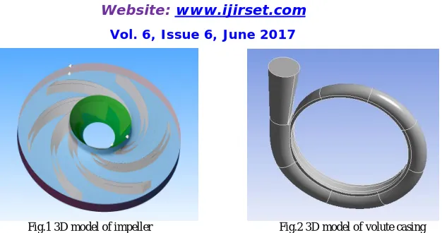
Fig.1 3D model of impeller Fig.2 3D model of volute casing
Fig.3 Finite element model of impeller Fig.4 Finite element model of volute casing
The maximum velocity is at the outlet of the impeller blades. The velocity of the flow decrease as it advances in the volute casing of the centrifugal pump due to continuous increasing cross sectional area of the volute.
The pressure distribution of a centrifugal pump impeller and volute casing for different mass flow rates are as depicted in the Fig.6 a, b, c & d. It is observed that the variation of pressure in the centrifugal pump is asymmetric in nature. The pressure steadily increases from inlet of the impeller to the outlet of the volute. The maximum pressure is observed at the outlet regions of the centrifugal pump. The minimum pressure is seen at the leading edge of the impeller blades.
a) Mass flow rate of 190 m3/hr b) Mass flow rate of 200 m3/hr
Fig.5 Velocity distribution
a) Mass flow rate of 190 m3/hr b) Mass flow rate of 200 m3/hr
c) Mass flow rate of 210 m3/hr d) Mass flow rate of 220 m3/hr
Fig.6 Pressure distribution
c) Mass flow rate of 210 m3/hr d) Mass flow rate of 220 m3/hr
3.2 Pump performance curves
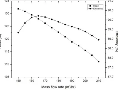
The Q-H and efficiency curve is depicted in the Fig.7 for impeller width of 19.1 mm and different mass flow rates.
Fig.7 Pump performance curve for design point
The maximum efficiency of 90.22% is obtained at 165 m3/hr mass flow rate which is offset from design point. The efficiency at design point is 88.96%. The deviation of 1.26 points is observed between the BEP and efficiency at design point. The efficiency at design point and BEP are very close to each other. The variation is insignificant may be due to computational error. Head variation is almost linear with mass flow rate. This is because software does not account for the losses in the centrifugal pump. It is observed that as the mass flow rate increases head decreases due to decrease in liquid pressure.
4.3 Investigation of pump performance with respect to impeller width
To investigate the effect of impeller width on the efficiency, head and shaft power, the impeller widths of 18.1 mm, 18.5 mm, 18.9 mm, 19.1 mm, 19.3 mm, 19.7 mm and 20 mm were selected, while the other parameters were kept constant. The impeller width estimated by vista CPD is 19.1 mm and the other values were obtained by increasing & decreasing design value by 1%, 3% and 5%.
The numerical simulation is carried out in ANSYS CFX for different impeller widths and mass flow rates. The obtained results for efficiency, head and shaft power with respect to impeller width for different mass flow rates are tabulated in the Table 4.1, 4.2 and 4.3 respectively.
Table 4.1: Efficiency for different impeller width
Mass flow rate (m3/hr)
Efficiency (%)
b2 =18.1 (mm)
b2=18.5 (mm)
b2 =18.9 (mm)
b2=19.1 (mm)
b2=19.3 (mm)
b2= 19.7 (mm)
b2= 20 (mm)
150 90.13 89.91 89.54 89.34 89.08 88.87 89.12
155 90.29 90.19 89.99 89.84 89.66 89.32 89.34
160 90.27 90.28 90.20 90.13 90.00 89.64 89.58 165 90.18 90.24 90.24 90.22 90.13 89.89 89.77 170 90.06 90.13 90.16 90.15 90.16 89.98 89.90 175 89.94 90.01 90.04 90.03 90.07 90.04 89.98 180 89.81 89.88 89.91 89.90 89.95 89.95 90.02
185 89.65 89.74 89.77 89.76 89.81 89.82 89.96
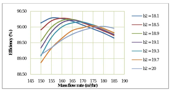
Fig.8 Efficiency Vs Mass flow rate for different impeller widths
The BEP shifts towards right side, for the increase in impeller width of the centrifugal pump. From the Fig.8 it is observed that the maximum efficiency of 90.29 % is observed at the impeller width of 18.1 mm and 90.02 % at the impeller width of 20 mm. There is a reduction of 0.27 points for increased impeller width. Thus the variation of efficiency is insignificant.
Table 4.2: Head for different impeller width
Mass flow rate (m3/hr)
Head (m) b2=18.1
(mm)
b2=18.5 (mm)
b2=18.9 (mm)
b2=19.1 (mm)
b2=19.3 (mm)
b2=19.7 (mm)
b2=20 (mm)
150 129.97 130.93 131.62 131.90 132.30 133.19 133.39 155 128.54 129.62 130.50 130.88 131.34 132.22 132.58 160 126.93 128.11 129.10 129.52 130.09 130.52 131.28
165 125.26 126.45 127.51 127.95 128.60 129.22 130.15 170 123.55 124.72 125.80 126.23 126.95 127.96 128.76 175 121.85 122.99 124.03 124.45 125.21 126.02 126.88
180 120.15 121.26 122.27 122.68 123.45 124.15 124.48
185 119.22 119.51 120.49 120.89 121.67 122.22 122.65
Fig.9 illustrates the pump head as a function of mass flow rate for different impeller width in the Centrifugal pump.
88.50 89.00 89.50 90.00 90.50
145 150 155 160 165 170 175 180 185 190
Effi
c
ie
n
c
y
(%
)
Mass flow rate (m3/hr)
b2 = 18.1
b2 = 18.5
b2 = 18.9
b2 = 19.1
b2 = 19.3
b2 = 19.7
Fig.9 Head Vs Mass flow rate for different impeller widths
The head developed reduces as the impeller width increases for the given mass flow rate as depicted in the Fig.9. The maximum and minimum pump head are observed at the impeller widths of 20 mm & 18.1 mm for mass flow rate of 150m3/hr & 185m3/hr respectively.
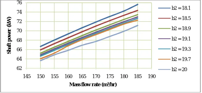
Table 4.3: Shaft power for different impeller widths
Mass flow rate (m3/hr)
Shaft power (kW) b2=18.1 (mm) b2=18.5 (mm) b2=18.9 (mm) b2=19.1 (mm) b2=19.3 (mm) b2=19.7 (mm) b2=20 (mm)
150 66.67 65.94 65.22 64.87 64.60 64.05 63.65 155 68.02 67.25 66.50 66.15 65.84 65.24 64.88 160 69.34 68.54 67.75 67.35 67.07 66.83 65.85 165 70.64 69.80 68.97 68.55 68.26 68.10 66.91 170 71.88 71.02 70.18 69.73 69.43 69.20 67.72 175 73.07 72.19 71.32 70.86 70.56 70.34 68.82 180 74.21 73.30 72.40 71.93 71.63 71.44 69.89 185 75.62 74.37 73.45 72.97 72.67 72.28 71.15
Fig.10 illustrates the shaft power as a function of mass flow rate with respect to different impeller width in the centrifugal pump.
Fig.10 Shaft power Vs Mass flow rate for different impeller widths
115 120 125 130 135
145 150 155 160 165 170 175 180 185 190
H e a d (m )
Mass flow rate (m3/hr)
b2 = 18.1
b2 = 18.5
b2 = 18.9
b2 = 19.1
b2 = 19.3
b2 = 19.7
b2 = 20
62 64 66 68 70 72 74 76
145 150 155 160 165 170 175 180 185 190
S h a ft p o w e r (k W )
Mass flow rate (m3/hr)
b2 = 18.1
b2 = 18.5
b2 = 18.9
b2 = 19.1
b2 = 19.3
b2 = 19.7
The shaft power consumption reduces as the impeller width is increased for the given mass flow rate as depicted in the Fig.10. The maximum and minimum shaft powers are observed at the impeller widths of 18.1 mm & 20 mm for the mass flow rate of 185m3/hr & 150m3/hr respectively.
V.CONCLUSION
A CFD analysis was carried out for different impeller width at different mass flow rates. Based on the analysis the results were discussed in the previous section, the following conclusions can be obtained.
The BEP shifts towards right side as the impeller width increases and vice versa.
The pump head decreases with increase in impeller width for the given mass flow rate.
For the given mass flow rate, the shaft power consumption reduces with the increase in impeller width.
From this study, it is observed that the impeller width is a major factor in deciding the hydraulic performance of the centrifugal pump.
REFERENCES
1. Val. S. Lobanoff, Robert R. Ross, “Centrifugal Pumps Design and Application”, second edition, a practical preference stressing hydraulic design
2. H. H. Anderson, “ Centrifugal Pumps”, third edition, Elsevier Science Publishers Ltd, 1993
3. Fan Meng et al. “Effect of two diffuser types of volute on pressure fluctuation in centrifugal pump under part-load condition”. ISROMAC, April, 2016
4. Sunsheng Yang, Fanyu Kong, Bin Chen. “Research on pump volute design method using CFD”, International Journal of Rotating Machinery, vol. 2011
5. Massinissa Djerroud, Guyh Dituba Ngoma and Walid Ghie. “Numerical Identification of Key Design Parameters Enhancing the Centrifugal Pump Performance: Impeller, Impeller-Volute and Impeller-Diffuser”. ISRN Mechanical Engineering, vol. 2011
6. Mohamed Salem, Tarek A Meakhail and Ibrahim. “Effect of Impeller Diameter on the Flow Characteristics of a Centrifugal Pump”. 4th World conference Applied Sciences, Engineering & Technology Kumamoto University, Japan, October 2015
7. Krishna Kumar Yadav, V.K. Gahlot, “Performance Improvement of Mixed Flow Pump Impeller through CFD Analysis”, IJRET, Volume: 04 Issue: 07, , page 243-247, July-2015
8. Ravi Teggin, M. S. Hebbal. “Effect of Blade Geometry on Hydraulic Performance of the Centrifugal pump”. IJIRSET, Vol.5, Issue 7, page 12380-12387, July 2016
9. Ashish J. Patel, Bhaumik B. Patel, “Design and Flow through CFD Analysis of Enclosed Impeller”, IJERT, Vol. 3 Issue 7, page 1366-1373 , July – 2014
10. Tilahun Nigussie, Edessa Dribssa, “Design and CFD Analysis of Centrifugal Pump”, IJERGS, Volume 3, Issue 3, page 668-677, May-June 2015
11. Ahmad Al-Obaidi et al. “Numerical studies of the velocity distribution within the volute of a centrifugal pump”, 27th International Congress of Condition Monitoring and Diagnostic Engineering, , Brisbane, Australia, September 2016