A Review on Optimization of Micro strip
Patch Antenna
Ashwin khandelwal1, Anushka Bhurke2, Rahul Koshti3
B.Tech. Student, Department of Electronics and Telecommunication, NMIMS, Shirpur, India12
Assistant Professor, Department of Electronics and Telecommunication, NMIMS, Shirpur, India3
ABSTRACT: Patch antenna is widely used antenna type in many applications. These are cheap, low profile, light weight ,small size , compatible with monolithic microwave integrated circuit (MMIC) designs..In this study the bandwidth and gain of the antenna are optimized by making change in the parameters like inset cut length, inset cut width ,substrate thickness, dielectric constant, strip width , feed line length ,z Top surface, meshing frequency.
KEYWORDS:Micro strip patch antenna, bandwidth , gain, optimization, z-parameter, s-parameter
I. INTRODUCTION
Wireless communication system has acquired a leadingplace in the industry due to its tremendous growth of wirelesstechnologies such as 3G, 4G, 5G, voice and internet services,in last couple of years [1], [2]. However, it is a challenging taskto provide enough capacity and high data rate wireless serviceswith a limited spectrum resource while maintaining the qualityof services. Due to recent advancement in the industries, it ispossible to design compact, low cost and compatible antennas.Micro strip patch antenna is one of key solutions due to itsattractive features like inexpensiveness, light weight, planarstructure and ease of fabrication which allows to combat the current requirements [1], [2]. A micro strip antenna includes aradiating patch placed on a dielectric substrate with a groundplane on other side of the substrate. This radiating patch canbe of different shapes such as circular, square, rectangular and annular. Though, patch antennas provide several advantagessuch as ease of fabrication, low profile, planer structure, integrablewith microwave circuits and high frequency operability,these antennas suffers from some disadvantages such as lowgain and efficiency, huge loss, surface wave excitation, narrowbandwidth [1], [2].Different design parameters play an important role in determininggain, directivity and the bandwidth of the antennas.Therefore, adjusting and optimizing design parameters such assubstrate thickness, substrate type, stacking patches, matchingnetworks, topology and material of substrates, meshingpatches, slots and shorting pins, different shapes and structures,can provide improved performance and structure [10].In this paper, some of existing techniques based on optimizationof different design parameters of micro strip antenna arereviewed.
II.LITERATUREREVIEW
resonators. Reconfigurable antennas have alsobeen discussed. Antennas with two patches was designed which has C type cuts with operating modes like two dual bandsand one wideband. Bandwidth of dual-band was kept2-5% while bandwidth of wideband was kept 33%. Anotherdesign proposed in the paper represents compact UWB micro stripantenna with built-in capability of discarding tri-bandfrequency notches. In Srisuji, an analysis of different types ofmicro-strip antennas such as dual frequency micro-strip patch antenna, star shaped antenna, E shaped antenna, Octagonalshaped patch antenna, was presented for different band offrequencies which can be used in different applications suchas, Wireless Local Area Network, Military, Radar, Wi- Fi, Wimax,GPS etc. Results demonstrated that octagonal antennas outperforms in wider bandwidth over the range of 2.5-18GHz and in radiation pattern as compared to different shaped antennas. In, [25], authors proposed a U-slot patch structureto obtain a structure with wideband behavior.
III.MICROSTRIPPATCHANTENNA
A micro strip antenna is a type of antenna made by using micro strip techniques on a PCB(printed circuit board).A simple micro strip patch antenna consists of metallic patch and ground in between of them is dielectric medium called the substrate. This substrate has a particular value of dielectric constant. The dimensions of a patch are smaller as compared to the substrate and ground. Dimensions of a micro strip patch antenna depend on the resonant frequency andvalue of dielectric constant [26].The idea of MPA(micro strip patch antenna) arouse from applications of printed circuits technology where it was not only used for circuitry component connections, transmission lines but also for radiating elements in electronics.Micro strip patch antennas are becoming increasingly useful because they can be printed directly onto a circuit board.They are very widely used in mobile phone markets and are low cost, and can be easily fabricated.
Micro strip patch antennas are used for communication purposes especially in military and civil applications.
The fig mentioned above is an example of rectangular patch antenna.MPA are generally available in many shapes including circular,square,etc.We will now study the designing equations of these micro strip patch antenna.
IV.DESIGNING EQUATION
For designing a patch antenna we derive the equations for all the dimensions of the patch and select the values for resonant frequency and a dielectric medium for that particular antenna type.
Here, essential parameters for design generally considered as: • fo = 2.4 GHz
• εr = 2.45
Following equations are considered for designing a patch antenna
1. Width (W):
where,
= Width of the patch = Speed of light
= value of the dielectric substrate
2. Effective Length (Leff):
3. Extended length (L):
4. Actual length (L):
L= Leff - 2L
V. EM OPTIMIZATION
OPTIMIZATION OF MIICROSTRIP PATCH ANTENNA:
Optimization technique is generally used in designing antennas. Optimization is widely used in almost all the antennas as it gives effective output of simulated output, it generates specific range or precise values for the parameters and graphs obtained are sharp and more precise.It can help designers to achieve their goal with much less effort. Some goals may even be impossible by manual tuning.But EM optimization may yield excellent results for you.
For simulation and optimization process of patch antennas we use IE3D software which is a full wave EM simulator and optimizer in which integral equations are solved using the frequency-domain method . IE3D has several built-in optimization methods that include Powell optimizer, genetic optimizer, random optimizer, and an adaptive optimizer. The variables for optimization defined by IE3D are controlled by their directions and bounds.[27]
SIMULATION:
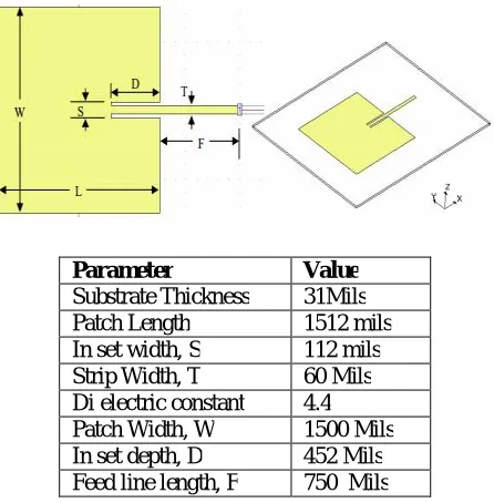
Before initiating the simulation process, we design a simple patch antenna by setting standard values of all the parameters.
Table :1 Simulation parameters
The whole process is executed in MGRID in IE3D and values are entered for the respective parameters. After designing a patch, an inset and a feed line is created.The values for the following are shown in the above table. Next we define a port, byselectingPort for Edge Group inthe advanced Extension and save the structure for further simulation process. Further we modify some parameters to reduce the width and set AEC Layers = 1 by changing the AEC ratio to 0.05.Now as we have set all the parameters correctly the structure is ready for simulation.Here the standard resonant frequency entered is 1.88 GHz But we simulate the structure from 1.7 to 2 GHz with 151 frequency points. Thus our simulation process is progressed
VI.OPTIMIZATION
After obtaining desired simulated results next step is to optimize those results. Before we start optimization, we should first consider the following.For the antenna we are discussing, we can adjust the length L to change the resonant frequency. We can adjust the inset depth D to tune matching. Hence we set our starting resonating frequency as 1.88 GHz now we can optimize one dimension at a time and it would make optimization much easier.
Previously we changed values of certain parameters hence it changes our structure. To change the shape of a structure, we need to change the locations of vertices. We need to identify which vertices we should adjust to change the L and D values. Therefore to change the patch length L, we can change the X-coordinate of Vertex Group 1. To change the inset depth D, we can change the X-coordinate of Vertex Group 2. As shown in the fig below
Parameter Value
We select vertices of the structure and enter some standard for further analysis by setting the tuning Angle = 0. Low Bound = -100, high bound=100
This process is repeated but the parameter’s values are changed to Low Bound as -200 and High Bound as 200. The structure is saved.Now the structure is ready for optimization.For optimization we select the optimize command in MGRID. The Optimization Setup dialog comes up same as the Simulation dialog box except some minor change. The frequency is changed to 1.88 GHz bydefining Re(S), 1st Parameter = (1, 1); and 2nd parameter Im[S(1,1)];
The saved structure is opened again by setting the frequencies in Frequency Parameters dialog where the Start Freq = 1.7, End Freq = 2.0, Number of Freq = 151.The optimization process is done.Now we define graphs for following parameters anddisplay S-Parameter,Z-parameters, VSWR(dB)
VII.RESULTS
S-Parameters
Figure 1. S -Parameter before optimization Figure 1.1 S-Parameter after optimization
Z- Parameters
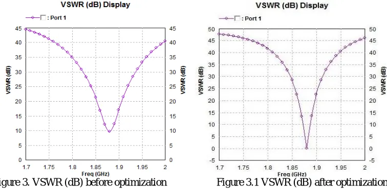
VSWR Graph
Figure 3. VSWR (dB) before optimization Figure 3.1 VSWR (dB) after optimization
VIII.CONCLUSION
From this work various curves of S, Z, and VSWR are obtained. From the curve of S-parameters,S11 represents how much power is reflected from the antenna, and hence is known as the reflection coefficient. For a frequency greater than 1.85 Ghz the magnitude of S11 is 0.5 and at a frequency less than 1.8 Ghz, the antenna will radiate nothing.
From the impedance curve shown in fig. 2.1 it is observed that at a frequency greater than 1.9 Ghz, the impedance offered by the antenna is 1.2 Kilo Ohms and the return loss is zero at the resonance frequency as shown in fig 3.1
REFERENCES
[1] F. Yang, X.-X.Zhang, X. Ye, and Y. Rahmat-Samii, “Wide-band E-shaped patch antennas for wireless communications,” IEEE Trans. Antennas Propag., vol. 49, no. 7, pp. 1094-1100, Jul. 2001.
[2] Y. Ge, K. P. Esselle, and T. S. Bird, “E-shaped patch antennas for high speed wireless networks,” IEEE Trans. Antennas Propag., vol. 52, no. 12, pp. 3213-3219, Dec. 2004.
[3] M. J. Rathod, “Comparative Study of Microstrip Patch Antenna for Wireless Communication Application,” International Journal of Innovation, Management and Technology, vol. 1, pp. 194-197, June 2010.
[4] G. Breed, “The Fundamentals of Patch Antenna Design and Performance,” High Frequency Electronics, pp. 50-51, March. 2009. [5] J. S. Vidya, P. Shrivastava, M. Susila, and T. R. Rao, “Ultra Wide Band Twin Eleven Slot Patch Antenna for Bandwidth
Enhancement,” International conference on Communication and Signal Processing, April 3-5, 2013.
[6] K. Song, Y. Yin, H. Xie, S. Zuo, and D. Xi, “A corner-truncated patch scheme of bandwidth enhancement for open slot antenna,” Proceedings of International Symposium on Signals, Systems and Electronics, 2010.
[7] N. Ripin, R. A. Awang, A. A. Sulaiman, N. H. Baba and S. Subahir, “Rectangular Microstrip Patch Antenna with EBG Structure,” IEEE Student Conference on Research and Development, 2012.
[8] J. S. Kuo and G. B. Hsieh, “Gain Enhancement of a Circularly Polarized Equilateral-Triangular Microstrip Antenna with a Slotted Ground Plane,” IEEE Trans. Antennas Propag., vol. 51, no.7, pp.1652 1656, July 2003.
[9] J. M. J. W. Jayasinghe, D. N. Uduwawala, “Design of broadband patch antennas using genetic algorithm optimization,” International Conference on Industrial and Information Systems (ICIIS), Jul 29Aug 01, 2010, India.
[10] A. A. Minasian, and T. S. Bird, “Particle swarm optimization of microstrip antennas for wireless communication systems,” IEEE Transactions on Antennas and Propagation, vol. 61, no. 12, pp. 6214-6217, 2013.
[11] M. T. Islam, N. Misran, T. C. Take, and M. Moniruzzaman, “Optimization of microstrip patch antenna using particle swarm optimization with curve fitting,” In Electrical Engineering and Informatics, 2009.ICEEI’09.International Conference on, vol. 2, pp. 711-714, 2009.
[13] I. Singh and V. Tripathi, “Micro strip Patch Antenna and its Applications:a Survey,” Int. J. Comp. Tech. Appl., vol. 2, no. 5, pp. 1595-1599,2011.
[14] B. S. A. I. Sandeep and S. S. Kashap, “Design and simulation ofmicrostrip patch array antenna for wireless communications at 2.4 GHz,”International J. Sci. Eng. Res., vol. 3, no. 11, pp. 1-5, 2012.
[15] A. Kumar and P. R. Chadha, “U shaped multiband microstrip patch antennafor wireless communication system and parametric variational analysis,”IFIP Int. Conf. Wireless Opt. Communication Networks, WOCN, pp.3-6, 2013.
[16] A. Rivera-Albino and C. A. Balanis, “Gain enhancement in microstrippatch antennas using hybrid substrates,” IEEE Antennas Wirel.Propag.Lett., vol. 12, pp. 476-479, 2013.
[17] S. Singh, N. Tyagi, N. Sinha, “Design and Analysis of Single Patch,2X1 and 4X1Microstrip Antenna Arrays,” International Conference forConvergence of Technology IEEE International Conference on RecentAdvances and Innovations in Engineering (ICRAIE- 2014), May 09-11,2014.
[18] A. Kumar and M. Kumar, “Gain enhancement in a novel squaremicrostrip patch antenna using hybrid substrates,” International Conf.Signal Process. Integr.Networks, pp. 659-662, 2014.
[19] R. Saha, S. Maity, and N. Trigunayat, “Enhancement of gain, bandwidthand directivity of a patch antenna by increasing dielectric layers of thesubstrate through micromachining technique for RFID application,” Conf.Proceeding - 2015 Int. Conf. Adv. Comput. Eng. Appl. ICACEA 2015, no.1, pp. 321-324, 2015.
[20] H. Errifi, A. Baghdad, A. Badri, and A. Sahel, “Design and Analysisof Directive Microstrip Patch Array Antennas with Series, Corporate andSeries-Corporate Feed Network,” International Journal of Electronics andElectrical Engineering, vol. 3, no. 6, pp. 416-423, 2015.
[21] M.H. Prio, Md. M. U. R. L Chandra Paul, A.K.Sarkar, “Total EfficiencyComparison of Different Shaped Microstrip Patch Antennas having DefectedGround Structure,” ICEEE, 2015.
[22] P. Jaikaran, M. Tiwari, and M. N. Patel, “Design and Simulationof Microstrip E-shaped Patch Antenna for Improved Bandwidth andDirective Gain,” IJETT, vol. 9, no. 9, pp. 446-450, 2014.
[23] M. Imran, Z. Huiling, M.S.S. Nawaz, K. Zakim, S. Zamin, and A. Khan,“A review on wideband microstrip patch antenna design techniques,” 2013International Conference on Aerospace Science & Engineering (ICASE),2013.
[24] T. Srisuji and C. Nandagopal, “Analysis on microstrip patch antennas forwireless communication,” 2015 2nd Int. Conf. Electron. Commun.Syst.,pp.538-541, 2015.
[25] M.E. Mohamed and D. Chatterjee, “Modal Analysis of Patch SlotDesigns in Microstrip Patch Antennas,” In Wireless Information Technologyand Systems (ICWITS) and Applied Computational Electromagnetics(ACES), 2016 IEEE/ACES International Conference on, pp. 1-2, Mar.2016.
[26] Muhammad AamirAfridi,”Microstrip patch antenna designing at 24GHz frequency” MS Telecommunication Engineering, University of Engineering and Technology (UET) Peshawar, Mardan Campus, Pakistan. March 25,2015.