Division VI
PERFORMANCE ASSESSMENT OF A HYBRID RCC-PSC
CONTAINMENT FOR INTERNAL OVER-PRESSURE LOADING
Moloy K Chakraborty1, Sourav Acharya1, Ajai S Pisharady1, A. D. Roshan1 and L. R. Bishnoi1
1 Scientific Officer, Siting & Structural Engineering Division, Atomic Energy Regulatory Board (AERB),
Mumbai, India
ABSTRACT
Performance Assessment of containment structure for internal overpressure loading can provide much insight into the impact of accident progression on external environment. The current problem deals with a single containment structure, which consists of a pre-stressed concrete (PSC) hemi-spherical dome and a reinforced concrete (RCC) cylindrical wall. The major challenge here is the numerical simulation of structural configuration of this type of containment including interfacial joint between RCC and PSC. The containment wall stems from competent rock strata. Pre-stressed concrete dome is structurally connected to reinforced concrete cylindrical wall by meridional pre-stressing tendons projecting from edge of the dome and anchored in a corbel at top of the wall. Dome is prestressed by two types of prestressing profiles; meridional and hoop type up to mid height of dome from springing level and Cartesian orthogonal layout in upper half. Structural interactions between dome and cylindrical wall at corbel location are simulated for different stages of pressure loading. Performance assessment is carried out using non-linear finite element technique available in ABAQUS software. Structural collapse is predicted using the criteria specified in USNRC RG 1.216. Structural responses of the containment structure at different loading stages are presented in the form of deformations, stresses and strains. Subsequently, air leakage rate with respect to internal pressure load steps are estimated considering strains in concrete sections to evaluate the functional failure.
INTRODUCTION
Containment structure is the last engineered barrier against release of radioactivity into public domain in case of a postulated radiation release accident. AERB safety code on design (AERB/SC/D) (2009) requires the containment to be designed taking into account all identified design basis accident scenarios. To demonstrate integrity of Indian containment against release of radioactivity under design extension conditions, oldest PHWR containment (RAPS-2) has been considered for the study. Integrity assessment of RAPS-2 containment structure has been performed to predict the behaviour of RAPS-2 containment under Design Extension Condition (DEC) and estimate containment leakage rates.
CONTAINMENT STRUCTURE
Internally, the building is highly compartmentalised with six floors and different rooms. The RAPS Reactor Building is designed for a nominal, maximum internal overpressure of 6 psi (gauge).
FINITE ELEMENT MODELING OF CONTAINMENT STRUCTURE
The geometric model of the containment is developed based on the gross cross section details available in report (1997). The containment is modelled using shell element along its centre line.
Four noded layered shell element with reduced integration scheme (S4R) is used for finite element discretization of the building. Element size of 0.5m was adopted. For this element size, behaviour of containment structure is captured adequately. The element size is so chosen that concrete crack (vertical) spacing is almost equal to one element size. This is used in estimation of leakage rate.
The layered shell element was chosen to optimize the modelling and analysis complexities in comparison to a 3D solid element FE model, while maintaining the overall behaviour as far as ULC evaluation is considered.
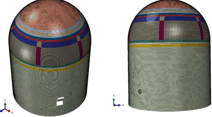
Transverse reinforcement available in the form of stirrups in the concrete cross section could not be modelled on account of adoption of the shell element. The embedded layers simulate reinforcement and prestress steel as smeared steel layers with thickness equal to the ratio of steel area to steel spacing. Profile of pre-stress tendons is modelled based on their layout and relative position in the wall and dome. FE discretization of RAPS-2 is shown in Figure 1.
Figure 1. Finite element model of RAPS-2 Containment Structure
MATERIAL MODELING
Material models have been developed using the material properties available in literature. Concrete damage plasticity model as available in ABAQUS-6.14 (2014) is used to model concrete material behaviour, steel rebars and prestressing steel. Brief description of the material models used for FE analysis of the containment structure is given below:
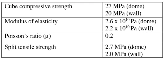
Constitutive relationship of concrete in compression and tension is simulated using Concrete Damage Plasticity model (CDP model), available in ABAQUS(2014). The main failure mechanisms assumed in the model are tensile cracking and compressive crushing of the concrete material. The failure surface is controlled by two variables representing the equivalent plastic strains in compression and tension. The plastic region of the stress-strain curve in compression is derived based CEB-FIP (2010) as reported by Alfarah, B. et. al (2017), which is capable of simulating non-linear behaviour of reinforced concrete elements. Fracture energy for tension is calculated based on CEB-FIP formula (2010) considering compressive strength. Linear stress-strain relationship is considered in post crack region of concrete in tension. Basic engineering properties of concrete is tabulated in Table 1, which is adopted in FE analysis.
Table 1: Concrete properties
Cube compressive strength 27 MPa (dome) 20 MPa (wall) Modulus of elasticity 2.6 x 10¹⁰ Pa (dome)
2.2 x 10¹⁰ Pa (wall)
Poisson’s ratio (µ) 0.2
Split tensile strength 2.7 MPa (dome) 2.0 MPa (wall)
Steel
The pre-stressing tendon steel is simulated as a smeared steel layer. Metal plasticity model has been used to simulate nonlinear material property for the prestressing steel. Freyssinet System of 12Ø7 having ultimate tensile strength of 69T is used as prestressing steel.Bi-linear stress-strain curve of pre-stressing steel is adopted. 85% of ultimate prestress force is assumed to be applied at the time of commissioning. The reinforcing steel is also modelled as a smeared steel layer assigned to different regions partitioned as per rebar diameter, spacing and orientation. Similar bi-linear stress-strain relationship is used for reinforcing steel considering appropriate yield strength.
BOUNDARY CONDITIONS
Fixed boundary condition is assumed at the base of containment wall. The pres-stressed dome is connected with reinforced concrete wall using meridional prestressing cables, in a word stitched using the cables. This can only be simulated in 3D solid element with suitable interaction. In this study, this is simplified with pinned/hinged connection between dome bottom edges with wall top edge (corbel portion). This is based on an assumption that there will not be any relative separation at junction of dome and wall. To investigate this assumption further study has been taken-up, which is excluded in the current analysis.
LOADING
Permanent loads acting on the containment are self-weight and prestressing load. Additionally, rise in internal pressure occurs during accident conditions. Static non-linear analysis for estimation of ULC is carried out in three load steps. Prestress is applied in the 1st load step as an initial stress in the tendons.
Average prestress loss of 25% for prestressing cables is considered for the period operational life. Dead load due to self-weight is considered through input density of material with acceleration due to gravity in the 2nd step and subsequently, internal pressure load is applied on entire inner surface of the containment
ASSUMPTIONS IN FE MODEL
(i) Containment wall (outer shell) is assumed to act independently of all internal walls and floors because from the report [2] it is evident that horizontal movement of internal floors relative to the perimeter wall is permissible through expansion joint between the floors and the wall.
(ii) The Reactor Building perimeter wall has a large number of penetrations, but only the openings for main airlock, emergency airlock and ventilation duct have been considered in the numerical model. (iii) From the report as referred above it is evident that containment wall is directly rests on the rock with
specified embedment length into the rock. Considering this fixed support condition is assumed at the base of containment wall.
(iv) Temperature load is not considered in the simulation work. (v) Embedded Parts (EP) are not modelled.
(vi) As shellelement FE model is adopted, shear reinforcement placed across the concrete section could not be accounted. However, its effect on ULC is not expected to be significant as the failure is governed by direct tension.
(vii) Individual pre-stressing tendons has not been modelled; they are idealized as smeared layers based on their diameter, spacing and position from centreof the containment cross section thickness. Due to this, variation of prestress force in each tendon cannot be accounted and thus average prestressing force is used as input for modelling the prestress loads.
FAILURE CRITERIA
The following failure definitions have been considered with failure criteria stated therein:
ULC is defined as a measure of safety margin above the design pressure, Pd. As per USNRC SRP 3.8.1,
NUREG-800 , which refers to USNRC RG-1.216 , for cylindrical prestressed concrete containments, the pressure capacity may be estimated based on satisfying both of the following strain limits: (1) a total tensile average strain in tendons away from discontinuities (e.g., hoop tendons in a cylinder) of 0.8 percent, which includes the strains in the tendons before pressurization (typically about 0.4 percent) and the additional straining from pressurization; and (2) a global free-field strain for the other materials that contribute to resist the internal pressure (i.e., liner, if considered, and rebars) of 0.4 percent.
Hence ultimate capacity will be estimated considering the pressure at which both the criteria i.e., (i) total strain in hoop prestressing tendon away from discontinuities reach 0.8% and (ii) a global free-field strain for hoop rebar reaches 0.4% for dome and only criteria (ii), i.e. global free-field strain for hoop rebar reaches 0.4%, for wall; and whichever reaches earlier will be considered as ULC of this hybrid containment.
Functional Failure
Functional failure needs to be defined based on the estimation of leakage. The pressure corresponding to an abrupt rise in leakage can be termed as functional failure. No guidance is available on this aspect of structural performance in the published literature. An attempt has been made in this article to estimate the leakage rate with respect to rise in internal pressure considering strain in reinforced concrete section.
ANALYSIS RESULTS AND PERFORMANCE INDICATORS
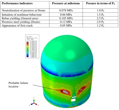
Table 2: Performance Milestone indicators of the Containment
Performance indicators Pressure at milestone Presure in terms of Pd
Neutralization of prestress at Dome 0.078 MPa 1.8 Pd
Initiation of nonlinear behaviour 0.06 MPa 1.5 Pd
Rebar yielding (General area) 0.105 MPa 2.5 Pd
Prestress steel yielding (Dome) 0.12 MPa 2.9 Pd
Appearance of first crack 0.05 MPa 1.2 Pd
Figure 2. Strain in outer hoop reinforcing steel at ultimate capacity, i.e. 2.7 times Design Pressure: 0.4% rebar hoop Strain in general area of containment as per NUREG Failure Criteria
Strain contour of outer hoop reinforcing steel is plotted in Figure 2 and probable location of failure is indicated based on 0.4% strain criteria. The failure location indicated in general area, away from discontinuity. Reinforcement strain history with respect to internal pressure (in times of design pressure, Pd) in this failure location is shown in Figure 3. It is seen that strain of 0.004, i.e. 0.4% is reached around
2.736 Pd. In dome, where prestress is present, criteria of 0.8% strain in prestress as well as 0.4% strain in
reinforcing steel reach beyond 2.736 Pd. Therefore, ULC of this hybrid containment is considered to be
2.736 Pd and failure is expected in cylinder away from main air lock.
Figure 3. Rebar Hoop Strain with respect to Internal Pressure at Failure Location
ESTIMATION OF LEAK RATE
Formulation of estimation of leak rate for RAPS-2 is done based on similar analytical study carried out by Acharya, S. et. al (2013) during AERB-USNRC SPE-3 and satisfactory demonstrated with comparison of experimental results. Structural responses obtained from the FE mathematical model are used to estimate the leak rate for different stages of pressure loading. A methodology has been used to calculate the air leakage through the containment building by accounting the cracked concrete cross section. The major input parameters for this formulation are plastic hoop strain of concrete composite section, which are obtained from finite element (FE) analysis of the containment. The input parameters are extracted from each element (as most of the elements are of similar size) for each load steps. Based on these inputs leak rate with respect to containment volume per hour is evaluated at different stage of internal pressure. Plastic hoop strains of concrete are checked across the thickness of concrete section for positive values, i.e. through-the-wall crack is generated.
Number of Cracks and Crack Width Calculation
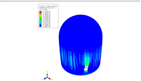
Figure 4. Maximum in-plane principal strain contour at ULC, i.e. crack pattern in concrete
Leak Rate formulation for concrete section
In this study, the formulation suggested by Rizkalla et al (1984) which is well applicable for wide range of concrete crack width as well as high differential pressure, is used, which is as follows:
j i j n n n n W B Q p RT k t p p , 1 3 2 2 1 2 2 2 1 1 2 2
(1) Where,
j i av j NW W , 1 3 3 42 . 1N = number of cracks = 1 in this case
Wav= average crack width = plastic strain x element length
3
0.81
3
0.063 195 . 0 133 . 0 av i NW Wn
3
0.428 6
3
0.3677 10 702 . 8 10 907 .
2 x Wi x NWav
k
In equation (1), Q = flux through the wall (ft3/s), B = crack length (ft), W = crack width (ft), t = wall
thickness, p1= upstream pressure (lb/ft2), p2 = downstream pressure (lb/ft2), µ = dynamic viscosity of air
or gas used (lb s/ ft2), T = absolute temperature (oR), R = gas constant (ft2/s2oR). W
av is the average crack
ft2/s2 oR, respectively. Estimation of leak rate using this formula generate leak rate with respect to
differential pressure for unlined concrete containment.
Assessment of Leak Rate
The following assumptions are made while formulating the calculations for the leak rate: (i) The estimation of leakage is only for internal pressure load case.
(ii) The crack width is functions of strain in outer hoop reinforcements.
(iii) There will not be any leakage till the concrete section is cracked. The strain onset of cracking is determined based on plastic strain of concrete across the thickness, i.e. maximum principal strain is positive.
(iv) Vertical through-the-wall cracks, due to hoop strains are considered for calculations as contribution of cracks in the circumferential direction are seen to be insignificant.
(v) Properties of air are considered constant throughout. The ambient temperature is considered as 25oC.
The step-wise calculation for estimating the leak rate is explained below:
(i) Maximum principal plastic strain of concrete element is checked for positive.
(ii) Strains of reinforcement in hoop direction (from the output of FE analysis) in each gauge area, (assumed here the same as finite element mesh), for different types of sections (based on thickness, location/state of stress) for the whole containment for a particular state of internal pressure are noted.
(iii) Crack widths are calculated for each element/gauge area multiplied with plastic strain. Crack depth is assumed to be the same as element height, as strain variation within an element is neglected.
(iv) Leakage is calculated for each element as per Equation (1).
(v) Total leakage is calculated by summing up the effective leak rates in all the elements. This leak rate is then converted to %volume of the containment building per hour.
(vi) Step-(i) to (v) is repeated for every load step of incremental internal pressure rise.
(vii) Finally, leakage in % Volume of containment building /hour is plotted with respect to pressure values in terms of design pressure, Pd.
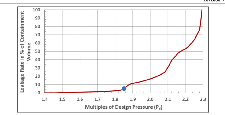
A computer code is formulated to calculate the leak rate estimation based on above steps. From the calculation of leakage it has been under stood that leak rate increases with increase in internal pressure of containment as expected. The leak rate follows a power law with respect to internal pressure. A plot of different stages of leak rates (%volume per hour) with respect to design pressure, Pd, is shown in Figure 5.
Based on the plot, it is understood that air leakage initiates around 1.5Pd and linearly progresses with
increase in internal overpressure till 1.85Pd. After this load step, leakage increases abruptly with increase
Figure 5. Variataion of leak rate (% volume per hour with design pressure Pd
CONCLUSION
Evaluation of containment leakage and estimation of ULC of RAPS-2 containment structure was taken up by AERB as a part of Consequence Analysis for Emergency Preparedness for RAPS (Level-2 & Level-3). Evaluation was carried out for internal pressure load. In addition to ULC for pressure load, behaviour of containment is evaluated with respect to various performance indicators based on defined criteria. Nonlinear analysis of the containment structure was carried out using a FE model considering nonlinear material properties of concrete and steel. Prestressing tendons and rebar steel were modelled as embedded layers.
ULC is defined as a measure of safety margin above the design pressure, Pd. ULC of containment is
estimated based on two criteria as mentioned in section. Pressure based on the criteria defined in RG 1.216 works out to be 2.736 Pd. Appearance of first crack in concrete occurs at 1.2 times of design
pressure. Air leakage initiates around 1.5Pd and linearly progresses with increase in internal pressure till
1.85Pd, which may be considered as functional failure of the containment structure.
REFERENCES
ABAQUS-610 (2014), “ABAQUS 6.14 User Documentation-Theory manual”, Dassault Systems Simulia, Corp., Providence, RI, USA.
Acharya, S., Pisharady, A and Bishnoi L. R. (2013), “prediction of air-leakage rate through lined containment under severe accident conditions”, Transactions, SMiRT-22, San Francisco, California, USA.
Alfarah, B., López-Almansa, F. and Oller, S., (2017). “New methodology for calculating damage variables evolution in Plastic Damage Model for RC structures”, Engineering Structures, Vol. 132, pp 70-86.
Atomic Energy Regulatory Board (AERB) (2009), Safety Code on “Design of pressurized heavy water reactor based nuclear power plants,” AERB/NPP-PHWR/SC/D Rev. 1.
Dawood, N. and Marzouk, H. (2010), “An analytical model for crack spacing of thick reinforced concrete plates”, Engineering Structures, Vol. 32, pp 472-482.
Report (1997) on “Feasibility of qualifying RAPS-1&2 containment repairs at full design pressure.” (Report No. RAPS/21000/M/97. Nuclear Power Corporation, VSB, Mumbai-94.
Rizkalla, S. H., Lau, B. L., Simmonds, S. H., 1984. “Air leakage characteristics in reinforced concrete,” J.
Struct. Eng. ASCE 110 (5), pp. 1149 – 1162.
United States Nuclear Regulatory Commission (USNRC). (2010). Regulatory Guide 1.216, “Containment structural integrity evaluation for internal pressure loadings above design basis pressure.”