55 | P a g e
UTILIZATION OF STEEL SLAG IN PAVEMENT
SUB-BASE
TAMANNA
M.Tech. Scholar, Civil Engg. Dept., B.M.U. Rohtak, Haryana
ABSTRACT
Now-a-days, the natural resources are depleting which is a major issue in the construction sector from which
the road segment cannot be excluded. Aggregate materials are depleting very fast and in short supply because
of extensive road construction process. Also the energy consumption is very high for blasting, quarrying,
crushing and transportation activities. On the other hand, bye-products, industrial wastes, and locally available
unused materials which are causing environmental and dumping problems, but they can be used for the
construction of roads. In the present study, an attempt has been made to utilize Steel Slag. By using suitable
tests and techniques, its gradation and other physical properties are studied. Conventional crushed aggregates
are also used simultaneously with the slag to satisfy the desired grading for using it in a particular layer as per
the specifications given by MORTH. The optimum percentage of slag is 80% that can be used in sub-base
layers. Physical properties have also been studied. From the observations, it is seen that slag have excellent
properties as road aggregates and hence can be used for application in road base and sub-base pavement layer.
Keywords: Steel Slag, California Bearing Ratio, Impact test, etc.
1.
INTRODUCTION:-
Generally, flexible or rigid pavements are used for the construction of roads. A flexible pavement consist of four
components:- soil subgrade, sub-base course, base course and surface course from which the transmission of
vertical load takes place i.e. from top (surface course) to the bottom (soil subgrade). A good flexible pavement
which transfers the compressive stresses through a wide area consists of well graded aggregates which are well
compacted. The base layer which lies immediately below the surface layer provides support to the pavement and
transmits the load to the layers below. The sub-base layer which is below to the base layer not just only provides
the support to the pavement structure and transmit traffic load to the subgrade but also provides drainage and
frost action. The sub-base mainly consists of two layers, the lower (filter) layer and upper (drainage) layer. The
56 | P a g e
drainage layer is composed of granular sub-base (i.e. GSB) materials that drains the water away which entersthrough surface cracks. [Yoder & witczak, principles of pavement design].
A rigid pavement generally consists of a cement concrete slab, with a granular base or sub-base course which is
provided below for the purpose of drainage, to control frost action, to control pumping and to control shrinkage
& swelling of the subgrade. Rigid pavement and flexible pavements are different because of their low
distribution phenomenon. In the rigid pavement, critical condition occurs due to flexural stress which is
maximum in the slab because of wheel load and the variation of temperature whereas, in flexible pavement
compressive stresses are distributed throughout. As compared to flexible pavement, rigid pavements have
noteworthy flexural strength or flexural rigidity but still flexible pavement is widely used in the construction due
to its smooth riding surface and low cost of construction. [Yoder &witczak].
However, in semi-rigid pavements bonded materials are utilized in the base course or sub-base course of
pavement layer, which gives them higher flexural strength as compared to conventional flexible pavement
layers. The materials for bound base or sub-base layer may consist of aggregate, soil or combination of
modification with stabilizers such as lime, cement, fly-ash or commercial stabilizers to give the desired strength.
1.1. Statement of the problem
Traditionally, the high way construction materials are also used in other activities of construction ( like dams,
buildings, power house, industrial setups etc.). Aggregates for the base & sub-base course used or composed of
crushed aggregates, sand, gravel or natural materials that provide the necessary strength and durability. To meet
the enormous demand of the construction the above natural aggregates are heavily consumed for the road
construction. The aggregates are extracted from hills through quarrying operations, crushing & transportation
etc. which are not only the major cause of environmental degradation in the form of loss of forest land, dust,
pollution hazards, vibrations, noise, etc. But also consumes a high amount of energy which depletes the sources
of energy. [Indian Highways, May 2011].
Huge quantity of waste materials are generated from industries like coal, iron, steel, etc. which causes a shortage
of dumping space and thereby it creates severe environmental pollution. Solid waste from steel industries such
as power plant flyash, tar sludge, acid sludge from by-product plant, steel flag, B.F. slag, steel scrap, coke
breeze, dolomite & calcined lime, etc. are generated in huge quantity that causes environmental degradation
57 | P a g e
1.2. Slag obtained from steel plantsAs of 2017, India is the world’s 3rd largest producer of crude steel (up from 8th in 2003), pig iron, sponge iron,
alloy & non-alloy steel. Slag is generated as a by-product during the manufacturing of pig iron & steel. During
the process of making of pig iron (in the blast furnace) and production of steel (in steel melting shop), slag is
produced as a by-product by the action of fluxes upon gangue materials with the iron ore. The slag primarily
consists of silicon, calcium, aluminium, iron, magnesium & manganese in various combinations. Under
controlled cooling slag becomes hard and dense, which can achieve the required strength to sustain heavy loads
thus making it especially suitable for use in road construction. [Indian minerals yearbook 2012].
The slag amount generated is so huge that dumping problem arises which can be hazardous for the
environment. So due to rapid growth in the construction industry and sufficient slag availability, it can be used
as a partial substitute for the natural aggregate materials in the base & sub-base course application in pavement.
Slag is a cheaper material than natural aggregate materials and also its availability is sufficient. When the slag is
used in bounded form in road sub-base then its hazardous effects can be decreased making it environmentally
sheltered. So because of the above factors slag can be used in road base & sub-base layer due to its cost
effectiveness & economic point of view in construction and by using slag in the construction industry
environmental issues can also be resolved.
2.
METHODOLOGY
Before the application of whether natural aggregates or locally available material or industrial
wastes/by-products, they must satisfy the strength parameters and desired physical properties for using it in the base or
sub-base pavement layer. Apart from these tests, the materials which could harm the environment are also
subjected to the chemical test and characterization to check whether they are suitable for the environment or not.
In this work chemical composition and characterization of the slag were undertaken. As per the respective
codes, specifications, literature, the physical properties of slag and natural crushed aggregate were determined.
The methods of the tests carried out in the work are presented below.
2.1. Physical Properties
In the present work, an attempt has been made on the utilization of slag in the sub-base layer of flexible
pavement. As per the specifications given by MoRTH (2013), for lower sub-base layer (i.e. filter layer) a closed
grading (i.e. Grading II for Grannular sub-base material) and for the upper layer (i.e. drainage layer) a uniform
grading ( i.e. GSB Grading IV) was used. For the usage in the drainage layer of the sub-base using GSB Grading
IV, the stabilization of crushed aggregates was done by using cement. The desired gradation of GSB Grading II
& IV as per the specifications given by MoRTH (2013) corresponding to the Indian Standards (IS)Sieve size are
58 | P a g e
IS Sieve Size(in mm)
%age passing the IS Sieve
GSB Grading-II GSB Grading-IV
53 100 100
26.5 75 – 100 55 – 80
9.5 55 – 80 -
4.75 40 – 60 15 – 40
2.36 30 – 45 -
0.425 15 – 20 -
0.075 0 – 5 0 - 5
Table 1 Grading Granular sub-base materials
2.1.1. Gradation
By sieve size analysis, gradation of the materials was determined by taking IS sieve. For 24 hrs., the materials
were stored in Oven and then cooled before sieve analysis. Wet sieving was done for finding the gradation of
the finer materials (i.e. finer than 4.75 mm) by washing the materials on 75µm IS sieve (until all the finer
materials were passed), retained materials dried in Oven (for 24 hrs.) and then after cooling sieving the dried
materials in the designated IS sieves which are finer than 4.75mm. Sieve size analysis of the 15 samples of slag,
5 samples each of 40, 20, 10, 6 mm crushed aggregates was done and after that the gradation results are shown
in the graphical forms by taking sieve size (in mm) along X-axis (log scale) and percentage passing
corresponding to it along Y-axis.
2.1.2. Blending of the Aggregates
After obtaining the gradation results of slag and crushed aggregates blending was done by different
proportions of crushed aggregates and also with slag to meet the desired gradation (either by using GSB grading
II & IV as specified in Table 1) on the basis of trial & error and the blend of aggregates for which the percentage
passing was within the desired limits was used for test & analysis.
2.2 TEST CONDUCTED ON MATERIAL
In the present work, different types of tests are conducted on the blended mixture obtained after the blending.
Various physical properties are measured by using these tests. The various test conducted on material are listed
below:
59 | P a g e
Impact Test
Combined flakiness index test Modified proctor test
California Bearing Ratio (CBR) Determination
3. RESULT
3.1. Gradation
The sieve size analysis for slag & crushed aggregate, samples are presented in graph shown in Fig.1
Fig.1: Graph which represents size V/s mean %age passing of slag & crushed aggregate
3.2. Blending:
3.2.1. Blending of slag with crushed Aggregates:
It is done to make the requirements of GSB Grading-II and GSB Grading-IV as per the specifications given by
MoRTH. The final proportion of aggregates were determined and it was given in table 2 & 3 after so many
60 | P a g e
Table 2:- Blending of slag with crushed aggregates to satisfy the desired gradation for GSB Grading-IIFig.2:- Blending of the slag with crushed aggregate to satisfy the desired gradation for GSB Grading-II
61 | P a g e
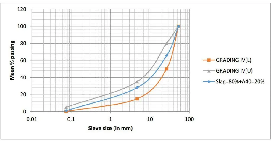
Fig. 3:- Blending of the slag with crushed aggregates to satisfy the desired gradation for GSB Grading-IV3.2.2.Blending of Crushed Aggregates
As per specifications given by MoRTH, to meet the requirements of GSB Grading-IV, the blending of different
size crushed aggregate was done by trial & error method.
62 | P a g e
Fig. 4:- Blending of crushed aggregates to have the desired gradation for GSB Grading-IV3.3. Other Properties
The physical properties of individual aggregates were determined as presented in table 5. The physical
properties of combination of aggregates were determined for their use in different layers by taking the optimum
proportion as obtained in the blending.
63 | P a g e
CONCLUSIONS
From the experiments conducted on the slag samples, and from the analysis of results, the conclusions drawn are
summarized below:.
The slag samples are well graded which require less amount of crushed (conventional) aggregates for
blending to meet the desired grading for use in different layers of sub-base.
Not more than 76% & 78% slag should be used for filter layer & drainage layer respectively. Impact value of slag, crushed aggregates are within prescribed limits.
Specific gravity is much higher for slag as compared tocrushed aggregates. MDD and CBR values are very
high.
REFRENCES
1. Aiban, S.A. “Utilization of steel slag aggregates for road bases” Journal of Testing & Evaluation 34, No.1
(2006) : 65.
2. Bhardwaj, Amit. "Literature Review of Economic Load Dispatch Problem in Electrical Power System using
Modern Soft Computing," International Conference on Advance Studies in Engineering and Sciences,
(ICASES-17), ISBN: 978-93-86171-83-2, SSSUTMS, Bhopal, December 2017.
3. Chaurand, P., Rose, J., Briois, V., Olivi, L, Hazemann, J. L., Proux, O., Domas, J., &Bottero, J. Y. “Environmental Impacts of Steel slag reused in road construction : A Crystallographic & Molecular (XANES) approach.” Journal of hazardous materials 139.3 (2007) : 537 – 542.
4. Indoria, R.P. “Alternative materials for road construction”, Indian Highways, May,2011.
5. Behiri, A.E.A.E.M. “Evaluation of Steel slag & crushed lime stone mixtures as sub-base material in the flexible pavement.” Ain shams Engineering Journal 4.1 (2013) : 43 – 53.
6. Emery, J.J., “Slag Utilization in Pavement Construction”, Extending Aggregate Resources, ASTM STP
774, 1982 , pp.95 – 118.
7. Er Amit Bhardwaj, Amardeep Singh Virdi, RK Sharma, Installation of Automatically Controlled
Compensation Banks, International Journal of Enhanced Research in Science Technology & Engineering,
2013.
8. IS:2386 (Part-I), “Methods of Test for Aggregates for Concrete: Particle size and shape” BIS, New Delhi,
1963.
9. IS:2386 (Part-III), “Methods of Test for Aggregates for Concrete: Specific Gravity, Density, Voids, Absorption, Bulking”, BIS, New Delhi, 1963.
10. IS: 2720 (Part 5), “Method of Test for Soils: Determination of Liquid Limit & Plastic Limit”, BIS, New
Delhi, 1985.
64 | P a g e
12. IRC : SP : 89, “Guidelines for Soil & Granular material stabilization using cement, lime & fly-ash”, IRC,New Delhi, 2010.
13. “Slag –Iron and Steel (Advance Release)”, Indian Minerals Year Book(2001):Part-II, 50th Edition.
14. Vikram Kumar Kamboj, S.K. Bath, J. S. Dhillon, “A Novel Hybrid DE-Random Search approach for Unit
Commitment Problem”, Neural Computing and Applications (ISSN: 1433-3058), Vol.28, No. 7, 2017,
pp.1559–1581. DOI:10.1007/s00521-015-2124-4 .
15. Yi, H., Xu, G., Cheng, H., Wang, J., Wan, Y., & Chen, H. “An overview of the utilization of steel slag.”