1559 | P a g e
A REVIEW ON WATER DESALINATION BY
REVERSE OSMOSIS PROCESS
Satayjit M. Deshmukh
1, Dr Samir K. Deshmukh2
1
Department of Chemical Engineering,
Datta Meghe College of Engineering, Airoli, Navi Mumbai.(India)
2Department of Chemical Engineering,
Priyadarshani institute of Engineering & Technology, Nagpur(India)
ABSTRACT
It is wellknown scarcity of water is the most well-known problem faced by the mounting population all around the world. The need for water covers not only the water needed for human consumption but also, most of the time, mainly the consumption in agriculture and industry. To suffice the needs of rising water needs, desalination has been increasing adopted all around the world. Desalination uses a huge amount of energy to remove a fraction of pure water from a saline water source. The main steps in the desalination process are based on using methods like evaporation and condensation or membrane technology in order to remove the dissolved salts from the salt water to obtain potable water .Our main objective is to study the process of Reverse Osmosis (RO) in better detail and explore its potential to the fullest. In RO driving force is represented by a difference between an applied transmembrane pressure (TMP) and the osmotic pressure difference across the
membranes. Highly concentrated solutions cannot be treated as a consequence of a physical limit imposed by
their osmotic pressure value.
Key words: Reverse Osmosis, Desalination, membrane technology
I. INTRODUCTION
Water is the most common essential in the world, however, 97% is seawater and only 3% is fresh water. The
availability of water for human consumption is decreasing due to increasing the ecological effluence. According
to the World Health Organization (WHO), about 2.4 billion people do not have access to basic cleanliness
amenities, and more than one billion people do not have access to safe drinking water. Moreover, the world‘s
population is likely to rise to nine billion from the current six billion in the next 50 years. The US geological
study found that 96.5% of earth‘s water is located in sea sand oceans and 1.7% of earth‘s water is located in the
icecaps. The remaining percentage is made up of brackish water, salty water found as surface water in estuaries
and as groundwater in salty aquifers [1,2]. constant water pollution and growing economies are driving
municipalities and companies to consider the desalination as a answer to their water supply problems. Although
1560 | P a g e
supports over 15% of world‘s population. The population of India as of March 31, 2011was 1,210,193,422persons [3]. Desalination uses a large amount of energy to remove a portion of pure water from a salt water
source. This system is described as filtering salty water through membranes and removing the salt through
electro dialysis and reverse osmosis. This procedure has worked for about 130 nations in North Africa and the
Middle East. With this system, these nations are currently producing six billion gallons of usable water a day.
Also, the United States has a total of about 1,200 desalinating plants, most of which are in modest-sized
communities. Recently, however, the desalination process has become much more practical for urban areas and
reverse-osmosis systems have made significant improvements. Reverse osmosis (RO) is a water purification
technology that uses a semi permeable membrane to remove larger particles from water. Inreverse osmosis, an
applied pressure is used to overcome osmotic pressure. Reverse osmosis can remove many types
of molecules and ions from solutions, including bacteria, and is used in both industrial processes and the
production of potable water. The result is that the solute is retained on the pressurized side of the membrane and
the pure solvent is allowed to pass to the other side. To be "selective", this membrane should not allow large
molecules or ions through the pores (holes), but should allow smaller components of the solution (such as the
solvent) to pass freely.
So it is necessary to do the process efficiency, flux performance and energy consumption for desalination of
salty water to meet the water crisis problem and global economic challenges. This paper explains a
detailed study of the Reverse Osmosis process.
II.PROCESSES FOR DESALINATION
Desalination is a procedure of removing dissolved salts from water also called as desalting. Desalination process
is divided into two broad categories namely 1) Thermal Processes, 2) Membrane Processes Thermal processes
include multi-stage flash, multiple effect distillation and mechanical vapour compression. Membrane processes
are detailed as –
2.1 Reverse osmosis (RO
):
Although the overall capacity of reverse osmosis is moderately small. Desalinationplants based on this process is one of the most popular types installed now-a-days. Reverse osmosis being a
membrane process; the salt is separated from the water by means of a selective membrane. Energy is required
exclusively to pump the feed water at a pressure above the osmotic pressure. However, higher pressures must be
used, typically 50-80 bar, in order to have an adequate amount of water pass through a unit area of
membrane.[4]
2.2 Electro dialysis (ED): As the name implies, this technology utilize an electrochemical separation process in
which charged membranes are applied to separate ionic species from a mixed aqueous solution of different
components and water through ion exchange membranes, which cause the concentration variations of solute in
dilute and concentrated compartment. [5]
1561 | P a g e
hydrophobic micro-porous membrane to support a vapour-liquid interface. Vapour pressure difference arises if atemperature difference is maintained across the membrane. As a result, water gets evaporated at the hot
interface, crossing the membrane in the vapour phase and condenses at the cold side, which gives rise to a net
trans-membrane water flux.[6, 7, 8]
The above mention text gives an overview about the techniques presently utilized for the purpose of
Desalination of water. The next section explains the process of Reverse Osmosis in great detail.
III.REVERSE OSMOSIS
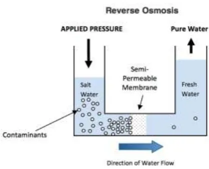
Figure No. 1 – Reverse Osmosis Diagram
Reverse Osmosis is the process of Osmosis in reverse. Where Osmosis is a natural phenomenon which can be
defined as the movement of pure water through a semi permeable membrane from a low to a high concentration
solution Osmosis occurs naturally without energy required, to reverse the process of osmosis you need to apply
energy to the saline solution. A reverse osmosis membrane is a semi-‐permeable membrane that allows the
passage of water molecules but not the majority of dissolved salts, organics, bacteria etc. However, you need to
‗push‘ the water through the reverse osmosis membrane by applying pressure that is superior than the naturally
occurring osmotic pressure in order to desalinate water in the process, allowing pure water through while
retaining back a majority of contaminants
3.1 PRINCIPLE OF REVERSE OSMOSIS
RO is a physical process that utilizes the osmosis phenomenon, that is, the osmotic pressure difference between
the salt water and the pure water to remove the salts from water. RO is a pressure-driven membrane process
where a feed stream flow under pressure through a semi permeable membrane, separating two aqueous streams,
1562 | P a g e
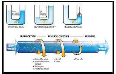
Figure No. 2: Representation Of Reverse Osmosis Process3.2 THEORY
RO is a separation method in which there is a separation of dissolved solids from water. This is done by
applying a differential pressure across a semi permeable membrane. As the name suggests, this process is the
exact opposite of the natural phenomena called osmosis. In osmosis, water molecules flow through a
semi-permeable membrane from the less concentrated solution to the more concentrated one, without external
influence. In reverse osmosis, pressure is applied to the more concentrated solution (containing dissolved solids)
which causes water molecules to flow through a semi-permeable membrane to the dilute solution (without
dissolved solids). ). The membrane, made of either cellulose acetate or polyamide, rejects most of the solids
creating two streams: one of pure water, product or permeate, and one with dissolved solids, concentrate or
reject. The ratio of pure water to raw feed water is called the recovery.
Absolutely, 100% of the feed water cannot go through the membrane because there must be enough concentrate
to flush away the rejected solids. Most RO systems provide a recovery of 25% to 90%, with 60% as the
accepted standard. The recovery and the overall performance of an RO system is govern by many factors. Feed
water quality is important because there are certain things in water that are known to harm RO membranes.
Treating the feed water with chemicals merely creates compatibility between it and the membrane. There are
four major factors which influence pre-treatment: colloidal & biological fouling, and the solubility of calcium
carbonate & calcium sulphate. The performance also vary with the feed water temperature. Due to higher
viscosities at lower temperatures, product rates drop with temperature.[10,11,13]
3.3
CHARACTERISTICS OF RO MEMBRANE
The membranes used for reverse osmosis method should have the following characteristics:
1. The membrane should be chemically, physically and thermally steady in saline waters.
2. They should be hydrophilic and have high water flux i.e. highly permeable to water and less susceptible to
fouling.
1563 | P a g e
4.
They need to be strong enough to withstand high pressures and variable feed water quality.Figure No. 3: Spiral Wound Reverse Osmosis Membrane[14]
3.4 WORKING
In an RO process plant, water will pass through the membrane, when the applied pressure is higher than the
osmotic pressure, while salt is retained. The membranes used for reverse osmosis have a dense layer in the
polymer matrix—either the skin of an asymmetric membrane or an interfacial polymerized layer within a
thin-film-composite membrane—where the separation occurs. In most cases, the membrane is designed to allow only
water to pass through this dense layer, while preventing the passageway of solutes (such as salt ions).As a result,
a low salt concentration permeate stream is obtained and a concentrated brine remains at the feed side.RO
operating pressure ranges from 17 to 27 bars for brackish water and from 55 to 82 bars for groundwater.
Brackish groundwater has a much lower osmotic pressure than groundwater; therefore, its desalination requires
much less energy. Also, lower pressures found in brackish-water RO system permit the use of low-cost plastic
components.[17]
A typical RO system consists of four major stages:
1. Pre-treatment system.
2. High-pressure pump.
3. Membrane module assembly.
4. Post-treatment system.
3.4.1 PRE-TREATMENT
Pre-treatment is vital when working with reverse osmosis and Nano-filtration membranes due to the nature of
their spiral-wound design. The material is engineered in such a fashion as to allow only one-way flow through
the system. As such, the spiral-wound design does not allow for back-pulsing with water or air agitation to clean
its surface and remove solids. Since accumulated material cannot be removed from the membrane surface
systems, they are highly susceptible to fouling (loss of production capacity). Therefore, pre-treatment is a
necessity for any reverse osmosis or Nano-filtration system., even as the membrane rejects the passage of salt
1564 | P a g e
the case of groundwater, they range from 800 to 1,180 psi (55 to 81.5 bar or 6 to 8 MPa). This requires a largeamount of energy. Where energy recovery is used, part of the high pressure pump's work is done by the energy
recovery device, reducing the system energy inputs
3.4.2 PRESSURE PUMP :
The high pressure pump provides the pressure needed to push water through the membrane, even as the
membrane rejects the passage of salt through it. Typical pressures for brackish water range from 225 to 376 psi
(15.5 to 26 bar, or 1.6 to 2.6 MPa). In the case of groundwater, they range from 800 to 1,180 psi (55 to 81.5 bar
or 6 to 8 MPa). This requires a large amount of energy. Where energy recovery is used, part of the high pressure
pump's work is done by the energy recovery device, reducing the system energy inputs
3.4.3
MEMBRANE ASSEMBLY:The membrane assembly consists of a pressure vessel with a membrane that allows feed water to be pressed
against it. The membrane must be strong sufficient to withstand whatever pressure is applied against it. Reverse
osmosis membranes are made in a variety of configurations, with the two most common configurations being
spiral-wound and hollow-fibre.
Figure No. 4: Layers of Membrane
Only a part of the saline feed water pumped into the membrane assembly passes through the membrane with the
salt removed. The remaining "concentrate" flow passes along the saline side of the membrane to flush away the
concentrated salt solution. The percentage of desalinated water produced versus the saline water feed flow is
known as the "recovery ratio". This varies with the salinity of the feed water and the system design parameters:
typically 20% for small groundwater systems, 40% - 50% for larger groundwater systems, and 80% - 85% for
brackish water. The concentrate flow is at typically only 3 bar / 50 psi less than the feed pressure, and thus still
carries much of the high pressure pump input energy. The desalinated water purity is a function of the feed
water salinity, membrane selection and recovery ratio. To achieve higher purity a second pass can be added
which generally requires re-pumping. Purity expressed as total dissolved solids typically varies from 100 to 400
parts per million (ppm or milligram/litre) on a groundwater feed. A level of 500 ppm is generally accepted as
the upper limit for drinking water, while the US Food and Drug Administration classify mineral water as water
1565 | P a g e
3.4.4 PH ADJUSTMENT:
The desalinated water is "stabilized" to protect downstream pipelines and storage, usually by adding lime or
caustic to avoid corrosion of concrete-lined surfaces. Liming material is used to adjust pH between 6.8 and 8.1
to meet the pure water condition, primarily for efficient disinfection and for corrosion control. Remineralisation/
PH adjustment may be needed to replace minerals removed from the water by desalination. Although this
process has proved to be costly and not very convenient if it is intended to meet mineral demand by humans and
plants. A very same mineral demand that freshwater sources provided previously. For instance water from
Israel‘s national water carrier typically contains dissolved magnesium levels of 20 to 25 mg/litre, while water
from the Ashkelon plant has no magnesium. After farmers used this water, magnesium deficiency symptoms
appeared in crops, including tomatoes, basil, and flowers, and had to be remedied by fertilization. Current Israeli
drinking water standards set a minimum calcium level of 20 mg/litre. The post desalination treatment in the
Ashkelon plant uses sulphuric acid to dissolve calcite (limestone), resulting in calcium concentration of 40 to
46 mg/litre. This is still lower than the 45 to 60 mg/litre found in typical Israeli freshwaters.[20,21]
3.4.5 DISINFECTION
Post-treatment consists of preparing the water for distribution after filtration. Reverse osmosis is an effective
barrier to pathogens, but post-treatment provides secondary protection against compromised membranes and
downstream problems. Disinfection by means of ultra-violet (UV) lamps (sometimes called germicidal or
bactericidal) may be employed to sterilize pathogens which bypassed the reverse osmosis process. Chlorination
or chloromination (chlorine and ammonia) is done by adding chlorine alone or chlorine with ammonia so as to
protect against pathogens which may have lodged in the distribution system downstream, such as from new
construction, backwash, compromised pipes, etc. Reverse Osmosis (RO) technology has undergone rapid
transition. This transition process has caused signification transformation and consolidation in membrane
chemistry, module design, and RO plant configuration and operation. RO technology is widely used because
of its high efficiency and it is cost efficient.[22]
3.5
EFFECT OF OPERATING PARAMETERS
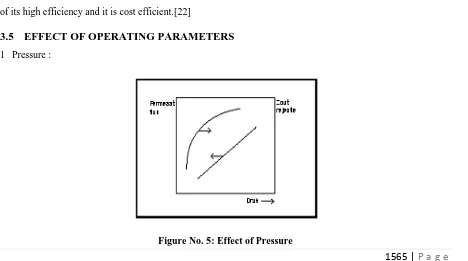
1 Pressure :
1566 | P a g e
When the effective pressure of the feed water is increased, the dissolved solids content of the permeate willdecrease, while the permeate flux increases.
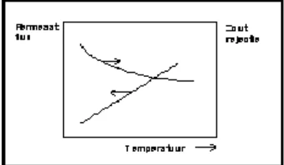
2.Temperature :
When temperatures increase and other parameters are constant, the permeate flux and the salt flow will increase.
Figure No. 6: Effect Of Temperature
3.
Recovery :Figure No. 7: Effect Of Recovery
Therecovery means the relation between the permeate flow and the feed water flow. When recovery increases,
the permeate flux will decrease and stagnate, when salt concentrations are of a value where osmotic pressure
equals feed pressure. When recovery increases, the salt retention will decrease.
4.
Salt Concentration Of The Feed Water :1567 | P a g e
The effects of the salt concentration of the feed water on the permeate flux and salt retention are shown here.IV.APPLICATIONS
4.4.1 In food industry
Besides desalination purposes, Reverse Osmosis System is also an application in filtering food liquids
(such as juices) instead of normal process so far. Researches were conducted on concentration of orange
juice and tomato juice. The advantage of RO System includes lower operating costs and the ability of
avoiding heat treatment process. This system is consistent with heat-sensitive substances such as proteins
and enzymes in most of food products. RO System is extensively used in the dairy industry to produce
whey protein powder (the remaining liquid from cheese production) and concentration of milk to reduce
shipping costs. Milk will be concentrated by Reverse Osmosis System; the solids total is from 5% up to
18-22% in order to reduce crystallization and lactose powder.
4.4.2 Car wash water treatment
Because of lower mineral content, Reverse Osmosis System is popularly used in car washing for the
final phase which prevents water spotting on the vehicle. RO System is popular in US for conserving
and reusing water within the car washing industry. Especially in areas which are effected by the
droughts, water conserving and reusing are incredibly important. It also helps car wash workshop
owners to reduce costs of drying vehicles and blowing equipment drying costs. In wine production
industry, Reverse Osmosis System is widespread used. About 60 Reverse Osmosis System machines are in
operation in Bordeaux (France) by the end of 2002.
4.4.3 In Syrup production
In 1946, a syrup factory started to use RO System to remove water from tree sap before boiling it to
produce syrup. Using RO System allows 40 – 50% of water volume to be removed from tree sap, it
helps to reduce energy consumption and limit exposure of the syrup to high temperatures.
4.4.4 In hydro production
For small-scale hydrogen production, RO System is occasionally used for preventing formation of
minerals on the surface of the electrode.
4.4.5 In fish cultivation
Many coral reefs and fish lakes are installed a Reverse Osmosis System to make an artificial mixture
of groundwater. Ordinary tap water may contain too much chlorine, chloramines, copper, nitrogen,
phosphate, silicate, and other chemicals which are harmful for sensitive creatures in coral reefs environment.
Pollutants such as nitrogen compounds and phosphates can lead to eutrophication. A great combination
of RO System and deionization is quite popular for fish cultivation treatment in coral reefs and lakes. It is ideal
1568 | P a g e
4.4.6 DesalinationReverse Osmosis System does not use heat to operate so it requires less energy than other desalination
methods in comparison. The typical desalination system of RO System includes: Pre-treatment, high pressure
pump, filter installation, chemicals for filter preservation and pH adjustment, disinfection and control panel.
Pre-treatment is very important to protect Reverse Osmosis filter and Nano filtration or ultra-filtration. This
requires high pressure pump. The filter wall must be strong enough to withstand the pressure of the
pump. RO filter is made of several constructions of matrix filter; with the two most common structures
are spiral and hollow fibre.
4.4.7 Antiseptic
Reverse Osmosis System is an effective barrier to prevent the pathogenic bacteria. However, in some
cases of water treatment process, the RO filter may be damaged and water will possibly have
recontamination. Antiseptic with a combination of RO System and ultraviolet light are totally safe and
sure for completely sterile water.[24]
V.CONCLUSIONS
Desalination technologies create new sources of fresh water from groundwater or brackish water. Various
desalination processes were studied. Due to the compactness and ease of operation in reverse osmosis process
forms a very effective method for desalination/purification of seawater and /or brackish water. The processes
that seemed to be convenient and implemented on an experimental and laboratory level was reverse osmosis.
Feed Water containing suspended particles, organic matter as well as inorganic salt may deposit on the
membrane and fouling will occur or damage the membrane because of applied pressure and size of particles.
REFERENCES
[1.] L.F.Greenlee,D.F.Lawler,B.D.Freeman,B.Marrot, and P. Moulin, ―Reverse osmosis desalination: water
sources, technology, and today‘s challenges,‖ Water Research, vol. 43,no. 9, pp. 2317–2348, 2009.
[2.] A. M‘nif, S. Bouguecha, B. Hamrouni, and M. Dhahbi, ―Coupling of membrane processes for brackish
water desalination,‖Desalination, vol. 203, no. 1–3, pp. 331–336, 2007.
[3.] R. Kumar, R. D. Singh, and K. D. Sharma, ―Water resources of India,‖Current Science, vol. 89, no. 5, pp.
794–811, 2005.
[4.] B. van der Bruggen, C. Vandecasteele, T. van Gestel, W.Doyen, and R. Leysen, ―A review of
pressure-driven membrane processes in wastewater treatment and drinking water production, ‖Environmental
Progress, vol. 22, no. 1, pp. 46–56, 2003
[5.] Wang, Xiao-lin; Gong, Y.; Yu, Li-xin; 2004 Process simulation of desalination by electrodialysis of
1569 | P a g e
[6.] M. Gryta, ―Desalination of thermally softened water by membrane distillation process,‖Desalination, vol.257, no. 1–3, pp. 30–35, 2010.
[7.] M. Khayet, ―Membranes and theoretical modeling of membrane distillation: a review,‖Advances in
Colloid and Interface Science, vol. 164, no. 1-2, pp. 56–88, 2011.
[8.] T. Mohammadi and M. Safavi, ―Application of Taguchi method in optimization of desalination by vacuum membrane distillation,‖Desalination, vol. 249, no. 1, pp. 83–89, 2009
[9.] A. S. Al-Amoudi, ―Factors affecting natural organic matter (NOM) and scaling fouling in NF membranes:
a review,‖ Desalination, vol. 259, no. 1–3, pp. 1–10, 2010.
[10.] B. van der Bruggen, C. Vandecasteele, T. van Gestel, W.Doyen, and R. Leysen, ―A review of
pressure-drivenmembraneprocesses in wastewater treatment and drinking water production,‖Environmental
Progress, vol. 22, no. 1, pp. 46–56, 2003.
[11.] H. S. Vrouwenvelder, J. A. M. van Paassen, H. C. Folmer, J. A. M. H. Hofman, M. M. Nederlof, and D.
van der Kooij, ―Biofouling of membranes for drinking water production, ‖Desalination, vol. 118, no. 1–3,
pp. 157–166, 1998.
[12.] S. Shirazi, C. Lin, and D. Chen, ―Inorganic fouling of pressure driven membrane processes-a critical
review,‖ Desalination, vol. 250, no. 1, pp. 236–248, 2010.
[13.] A. M. Farooque, A. S. Al-Amoudi, and A. M. Hassan, ―Chemical cleaning experiments for performance
restoration of NF membranes operated on groundwater feed,‖ in Proceedingsof the IDA Conference,
Manama, Bahrain, March 2002.
[14.] A. S. Al-Amoudi and A. M. Farooque, ―Performance restoration and autopsy of NF membranes used in
groundwater pre-treatment,‖ Desalination, vol. 178, no. 1–3, pp. 261–271, 2005.
[15.] K.W. Lawson, D.R. Lloyd, Membrane distillation, J. Membr. Sci. 124 (1) .1–25, 1997
[16.] A.M. Alklaibi, N. Lior, Transport analysis of air-gap membrane distillation, J. Membr. Sci. 255 (1–2)
.239–253, 2005
[17.] B.L. Pangarkar, M.G. Sane,M. Guddad, Reverse osmosis and membrane distillation for desalination
ofgroundwater: A review. ISRN Mater. Sci.;1–9, 2011.
[18.] M.N. Chernyshov, G.W. Meindersma, A.B. de Haan, Modelling temperature andsalt concentration
distribution in membrane distillation feed channel, Desalination 157 (1–3) 315–324,2003.
[19.] S. Kimura, S.-I. Nakao, S.-I. Shimatani, Transport phenomena in membrane distillation, J. Membr. Sci.
33 (3) ,285–298, 1987.
[20.] Satyajit M. Deshmukh, Anil C. Ranveer, Prashant M. Ingole, Dr Sameer K. Deshmukh, ―Integrated
method for desalination of seawater‖, ‖ International Journal of Advanced Technology in Engineering
and Science,Volume 4, Special Issue (01), Page No. 22-31, (ISSN: 2348-7550). May 2016
[21.] Satyajit M. Deshmukh, , Dr Sameer K. Deshmukh, Prashant M. Ingole, ―Integrated Membrane Distillation
and Reverse Osmosis for Desalination of Water‖ International Journal of Emerging Trends in Engineering
and Basic Sciences.ISSN number 2349-6967. Volume 2 Issue 2. March-April 2015.
1570 | P a g e
INTEGRATED REVERSE OSMOSIS (R.O.) AND MEMBRANE DISTILLATION ( M.D.)‖, ‖International Journal of Advanced Technology in Science and enginffring, Volume 6, Special Issue (01), Page No. 580-591, Dec 2017 (ISSN: 2319-8354)
[23.] Lawson, K.W.; Lloyd, D.R; 1997 Membrane distillation Review Journal of Membrane Science 124 ,1997.
1–25Banat and Simandl; 1994, Alklaibi and Lior; 2006.
[24.] S. Otles and S. Otles, ―Desalination techniques,‖ Electronic Journal of Environmental, Agricultural and
Food Chemistry,vol. 4, no. 4, pp. 963–969, 2004
[25.] Gryta, M. Osmotic MD and other membrane distillation variants. J. Membr. Sci., Vol.246, No.2, 45–56,
![Figure No. 3: Spiral Wound Reverse Osmosis Membrane[14]](https://thumb-us.123doks.com/thumbv2/123dok_us/7784403.1287221/5.595.173.444.138.294/figure-no-spiral-wound-reverse-osmosis-membrane.webp)