2149 |
P a g e
MICROSTRIP PACTH ANTENNAS FOR IRNSS
APPLICATION
1
Vibhanshu Dubey,
2Neeraj Sharma
1,2
Department of ECE, AKGEC Ghaziabad,
Dr. A.P.J. Abdul Kalam Technical University, Lucknow (INDIA)
ABSTRACT
This paper presents a study about Microstrip Circular patch antenna for S band satellite
application. We proposed it for Indian Regional Satellite System which having the
operational frequency band of 2-4 GHz. The DGS (Defective Ground Structure) implies a
defective ground structure in place of a simple conventional ground structure. The developed
design is succeed to achieve a low profile return loss. We simulate the prototype on HFSS
with Rogers RT duroid and FR4 Epoxy materials. The proposed antenna achieved the
bandwidth of 166.2 MHz The proposed prototype is consisting of two frequency bands for
operation with low profile S parameters.
Index Terms – Microstrip Patch antenna, Circular patch, DGS, IRNSS, Return loss.
I. INTRODUCTION
The requirement of newly designing techniques in place of conventional designing methodology is increasing as
the need of simple, compact and durable devices reaches on peak. The conventional satellite antennas consist
bulky size and complex designing so that it looks difficult to apply them for mobile and small utilities. For
example as mobile GPS systems, small navigation systems which have to matched with satellite and installed in
various applications like aircrafts, public transports or various security and public utilities. So as the applications
of these fields are robust and almost typical, there is a need to improve the designing of antenna technology so
as small in size, less complex, easy to designing and fabrication, better improved parameters. For achieving
maximum improved parameter from same size antenna there are lots of designing techniques available.
If we talk about the satellite systems, it has worldwide uses for many utilities. The surveillance and navigation is
one of its crucial applications. We are very much familiar with GPS for universal tracking and surveillance, but
GPS is an American standard service. The biggest limitation of GPS system is that it is not reliable in hostile
situation which India already faced during Kargil war when USA refused to provide information data. So the
need of an own navigational and surveillance system is much required.
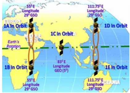
IRNSS is such an independent, regional satellite system approached by India for India and regional
territories. It is named as Indian Regional Navigational Satellite System. It is a 24 hours operational Indian
2150 |
P a g e
stationary orbit. The crucial advantage of geo stationary orbital satellite is that it provides large signal coverage
with minimum number of satellite. IRNSS is supposed to operate on two modes of services – (a) Standard
Positioning System (b) Restricted Services. SPS will be open to all civilian uses whereas RS is only for military
users or authorized users. RS will consist of an encrypted type of service so that only authorized authority can
utilize this service. Figure-1 shows the satellite positions of IRNSS.
Figure 1 IRNSS Satellite Positions
The operating frequencies of IRNSS are supposed to be operated on L5 band (1176.45 MHz) an S band
(2492.08 MHz). The distribution of 7 satellites of IRNSS is as 3 satellites are installed in Geo Stationary orbit
and 4 in Geo Synchronous orbit.
II.ANTENNA REQUIREMENTS
Antenna is an essential component any type of a wireless communication system. It works like transducers as it
converts EM radiation into electrical signal. For mobile use and device flexibility it should be required that the
antenna should be light weighted, small sized easily producible. For satellite use it requires that it should
perform circular polarization radiation. While considering the necessity of Antenna and its model for GNSS
system, a short observation of features of small strip antenna development in 1970’s is made and
its important options are : consists of four elements specifically, patch, ground plane, substrate, and the
feeding half. ii) it's tiny in size and thus lightweight weight. Due to size reduction it's usually utilized in
handsets, GPS receivers and different factory-made wireless merchandise. By using modern fabrication
methods, we can produce antennas as small and can be mounted on both planar and flat surface. The
traveling Radiation energy, formed on spiral arms, permits for broadband performance (due to mutual
coupling development occurring between arms of spiral and through propagation enable the Radiation energy to
travel through the spiral arm.
III. ANTENNA FOR IRNSS
As discussed earlier, we concluded on the points that antenna system for such a type system should be light
weighted, easy to manufacture, circularly polarized and with a low profile return lose. Microstrip patch
2150 |
P a g e
Spiral Slot/different slots on a similar substrate ii) /circularly polarized radiation / RHCP radiation (Right Hand
Circularly Polarized radiation iii)Tri-band or Multiband resonant frequencies iv)Horizontal and Vertical
Stacking, multi-stacking and/or staking with QIFA. v) shape attributes of associate antenna [antenna using a
shape or self-similar style to extend the perimeter among a given total expanse or volume] vi) operation with
Single layer or 2 layer or multilayer substrate, vii) Reduction in size viii) dielectric loss tangent, thermal growth
and conductivity properties of Microstrip patch antennas has been planned by numerous man of science for
application of GNSS and IRNSS Satellite navigation system. If we discussed about the various antenna
geometries which are familiar for various patch designs, so basically there are basically five types of patch
geometries – i) rectangular patch ii) circular patch, iii)annular patch iv) elliptical patch v) Triangular patch. In
this paper we discussed the comparative study of circular patch and annular ring patch geometries [1].
The both comparisons are based on the simulation testing on HFSS. We consider two geometries in all of above
because these designs are easy to fabricate, easy to designs, less complex and with variety of designs. Till now
we discussed the satellite part and now we are going to showing antenna technology proposed for such a system.
IV ANTENNA DESIGNING
There has been an ever-growing demand of multi band radio system, which is revolutionizing the major
advances in wireless communication, networking and radar [2]. The antenna should possess the small size,
conformal, low cost, ultra wide band and ease of fabrication. Microstrip – like antenna is one of them. The
limitations of the conventional microstrip antenna are its narrow bandwidth, efficiency, and size [3-4]. The
Microstrip antenna is an efficient radiator around half wavelength long. As the size of the antenna becomes less
than λ/2, the radiation resistance, gain and bandwidth of the antennas deteriorate. Circular geometry is a very good solution for this problem [4]. These structures recognized by their self-similarity, space filling properties.
In the recent years, geometrical properties of self-similarity and space filling nature have motivated antenna
research to meet the target of multi-band wideband and miniaturization [5-6].
2151 |
P a g e
Above figure shows an simple circular microstrip patch antenna with partial ground structure. The proposed
antenna has the following geometry parameters –
Length – 30 mm thickness of substrate is 0.83 mm
Width – 35 mm
The simulation is performed on the FR-4 Epoxy substrate with dielectric constant of 4.4.
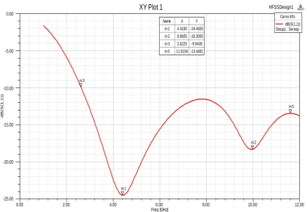
V. RESULTS & SIMMULATION
The simulated results are given as follow-
0.00 2.00 4.00 6.00 8.00 10.00 12.00 Freq [GHz]
-25.00 -20.00 -15.00 -10.00 -5.00 0.00
d
B(S
(1
,1
))
HFSSDesign1
XY Plot 1
ANSOFTm 1
m 2 m 3
m 5 Curve Info
dB(S(1,1)) Setup1 : Sw eep
Name X Y
m 1 4.4100 -24.4926
m 2 9.9925 -18.3055
m 3 2.6225 -9.9439
m 5 11.6150 -13.4481
Fig. 2 – S parameters of the given Circular Patch microstrip patch antenna
The figure shows the S parameter of circular patch antenna. S parameters are also termed as reflection
coefficient or return also some time. Practically S parameters can be measured by network analyzer of
appropriate frequency range. In above figure, it shows very clearly that the return loss of the circular patch
antenna is about -24 dB at 4.4 GHz freq. From above result also cleared that the bandwidth achieved by this
2152 |
P a g e
0.00 2.00 4.00 6.00 8.00 10.00 12.00
Freq [GHz] 0.00
2.50 5.00 7.50 10.00 12.50 15.00 17.50 20.00 22.50
d
B(V
SW
R
(1
))
HFSSDesign1
XY Plot 2 ANSOFT
m 1
m 2
Curve Info dB(VSWR(1)) Setup1 : Sw eep Name X Y
m 1 4.3550 1.0425 m 2 9.9650 2.1159
Fig.3 - VSWR of the Circular patch antenna.
VSWR stands for Voltage Standing Wave Ratio, and is additionally stated as Standing Wave Ratio (SWR).
VSWR could be a perform of the reflection constant, that describes the facility mirrored from the antenna. It is
usually supposed to lie between 0-2 dB, from above figure 3 it is cleared that the VSWR of given antenna is
about 1 &2 , which is acceptable.
VI. ANNULAR RING PATCH ANTENNA
Ayappam M proposed an annular ring antenna with a low profile return loss. We also observed that the annular
ring patch antenna gives much better results than a simple conventional circular patch antenna.
2153 |
P a g e
The above figure shows the step to step variation from a circular patch antenna to a annular
ring patch antenna.
Fig. 5- Annular ring patch antenna
The circular patch geometry has been modified by inserting a circular slot. By inserting the slot, the current path
on the patch increases resulting in better antenna efficiency. By varying the size of the slot the effective radius
of the patch decreases thereby increasing the resonant frequency of antenna. In the proposed antenna design
after inserting the circular slot higher bandwidth of about 440 MHz and low return loss of -31 dB was obtained
thereby reducing the narrow bandwidth problem. Higher bandwidth makes them suitable for embedded
application.
1.00 1.50 2.00 2.50 3.00 3.50 4.00 4.50 5.00
Freq [GHz] -35.00
-30.00 -25.00 -20.00 -15.00 -10.00 -5.00 0.00
d
B(S
(1
,1
))
HFSSDesign1
XY Plot 1 ANSOFT
m 2 m 4
m 7
m 8
m 9 m 10
Curve Info dB(S(1,1)) Setup1 : Sw eep
Name X Y
m 2 4.3700 -7.0023 m 4 1.4900 -5.4420 m 7 4.8700 -10.3551 m 8 1.6700 -17.9387 m 9 4.5500 -31.9860 m 10 4.4300 -10.2410
2154 |
P a g e
The Annular ring patch design gives much improved low profile return loss as compared to conventional
circular patch. We can see it clearly that at 4.5 GHz it gives -31.9 dB return loss which is much improved from
conventional circular patch antenna.
1.00 1.50 2.00 2.50 3.00 3.50 4.00 4.50 5.00
Freq [GHz] 0.00
5.00 10.00 15.00 20.00 25.00
d
B(V
SW
R
(1
))
HFSSDesign1
XY Plot 2 ANSOFT
m 1
m 2 Curve Inf o
dB(VSWR(1)) Setup1 : Sw eep
Name X Y
m 1 1.6700 2.2144 m 2 4.5500 0.4372
Fig. 7 – VSWR of Annular patch antenna
Figure 7 shows VSWR of the annular patch antenna. It is about range 0-2 dB which is quite acceptable.
VII. CONCLUSION
A comparative study between circular patch antenna and annular ring patch antenna is discussed in this paper.
We also discussed the antenna requirements for IRNSS and also discussed a brief introduction of IRNSS. The
constant study showed that broadband characteristics are achieved for a smaller antenna solely with the
appropriate selection of parameters. The above antennas were designed for 4.4 GHz frequency and their
simulated results are comparing with each other.