Article
LW-CCA: A New Energy Efficient Method for
Low-Power Radio Operation in Wireless Sensor Networks
for IoT Applications
Mehdi Amiri Nasab 1, Shahaboddin Shamshirband 2, 3* and Anthony Theodore Chronopoulos 4,5, Amir Mosavi 6, Narjes Nabipour 7, *
1 Internet of Things Laboratory of Iran (ISVA), Hamedan, Iran; [email protected]
2 Department for Management of Science and Technology Development, Ton Duc Thang University, Ho Chi Minh City, Viet Nam
3 Faculty of Information Technology, Ton Duc Thang University, Ho Chi Minh City, Viet Nam; 4 Department of Computer Science, University of Texas, San Antonio, USA;
5 Department of Engineering & Informatics, University of Patras, Greece; [email protected]
6 Institute of Structural Mechanics, Bauhaus Universität Weimar, Germany; [email protected] 7 Institute of Research and Development, Duy Tan University, Da Nang 550000, Vietnam;
* Correspondence: [email protected], [email protected]
Abstract: The radio activity in wireless sensor networks (WSN) in the Internet of Things (IoT) applications are the most common source for power consumption. However, recognizing and controlling the factors affecting radio activity can be valuable for managing the node power consumption. ContikiMAC is a low-power Radio Duty-Cycle protocol in Contiki OS used in WakeUp mode, which is a clear channel assessment (CCA) to check radio status periodically. The time spent to check the radio is of utmost importance for monitoring power consumption. It can lead to false WakeUp or idle listening in Radio Duty-Cycles and ContikiMAC. This paper presents a detailed analysis of radio WakeUp time factors of ContikiMAC. Then, we propose lightweight CCA (LW-CCA) as an extension to ContikiMAC to reduce the percentage of Radio Duty-Cycles in false WakeUps and idle listenings by using dynamic received signal strength indicators (RSSI) status check time. The simulation results in the Cooja simulator show that LW-CCA reduces about 8% energy consumption in nodes while maintaining up to 99% of the packet delivery rate (PDR).
Keywords: Internet of Things, IoT, Wireless Sensor Networks, ContikiMAC, Energy Efficiency, Duty-Cycles, Clear Channel Assessments (CCA), Received Signal Strength Indicator (RSSI).
1. Introduction
The advancement of hardware systems for IoT is an essential research domain of large-scale wireless sensor networks (WSN). In this realm, the development of low-power wireless communication is of utmost importance. Since these types of devices are usually powered by low capacity batteries to provide both sensing and actuation capabilities, managing power consumption is one of the major challenges in designing their hardware and software. The radio is the greatest source of power consumption in a sensor node. Although the sensor network improves and enhances the performance of other technologies, it also presents challenges due to some of their inherent characteristics and location in a variety of environments. The nodes comprising a wireless sensor network are expected to be small, reliable, low cost, and low power. In some situations, the nodes are in hard-to-reach areas, so their power supply is usually battery or harvest energy from the environment.In both models of power supply the management of power consumption in the nodes
is mandatory, in the former case to avoid battery replacement and in latter case to reduce the cost of the energy harvesting system[1]–[3].
Contiki OS is a well-known lightweight operating system that can be used to manage low-power wireless platforms based on wireless internet communication. In wireless networks, in many cases, it is necessary to relay data between nodes to reach the destination. The Radio Duty Cycle (RDC) protocols available on Contiki OS allow end nodes and even relay nodes to sleep and save energy between each message sending or relay, so the network lifetime is increased. ContikiMAC is a radio duty cycling protocol available in Contiki OS based on the Low Power Listening (LPL) mechanism[4]. It uses the periodic WakeUps method to monitor the communication medium for ongoing transmissions from neighbor nodes. ContikiMAC tries to reduce the amount of energy consumed by radio activities by using pairs of Clear Channel Assessments (CCA) in every sleep and wake up sequence and providing a model of radio management. CCA identifies to recognize the difference interference by measuring the Received Signal Strength Indicator (RSSI) thresholds [5],[6].
Obviously, much of the amount of power consumedin ContikiMAC is spent on the WakeUps of nodes. The WakeUp is known as a single radio check with a chance to detect the activity of a radio. The WakeUps can be considered in three categories, positive WakeUps, which results in the receipt of the packet, false WakeUps, which results in noise or interferences, and idle listening [7]. Idle listening occurs when the communication medium monitoring does not detect any activity on the radio. Implementing the CCA model on WSN hardware to recognize the different interference is extremely challenging due to the limitations of the low power radio, such as TI CC2420. The power consumption over Radio listening mode(Rx) is unavoidable. Nodes should periodically listen to the radio channel to reduce the communication latency in network, even if data traffic is slow [8]. In this paper, we carefully investigate the time factors associated with a radio WakeUp on the ContikiMAC and to reduce the radio power consumption by dynamic radio check time in WakeUps on the Rx mode. RSSI status check is an essential timing parameter during radio check-in nodes. Consequently, in this research particular attention has been paid to RSSI status check to enable an efficient manipulation of radio check within the limits during the Rx. The maximum timing of radio check is used when RSSI is either new or identified as a positive WakeUp. Otherwise, the false WakeUp or idle listening are associate with minimum timing of radio check. In the proposed method the radio check is essentially based on RSSI where the use of CCA is minimized. CCA is used only for the purpose of RSSI validation and classification.
The remainder of this paper is structured as follows. Section 2 provides an overview of related works. Section 3 identifies the hardware and software tools, as well as the scenario used in this paper. Section 4 highlights the challenge of ContikiMAC in WakeUps as a problem statement. Section 5 proposes a Light Weight Clear channel Assessment (LW-CCA) method to reduce power consumption in WakeUp mode. Section 6 contains simulations to compare the proposed method to the ContikiMAC base method. Section 7 presents concluding remarks and future work.
2. Related works
One of the most important challenges in implementing some IoT applications is the power management of hardware platforms. Nowadays, researchers are using many new technologies to minimize radio power consumption so that they can pave the way for IoT. The communication to sending and receiving data on the network is typically the most energy-consuming task in IoT applications[9]. Since the communication of the nodes is in the radio WakeUp state, soa lot of effort has been devoted to designing energy-efficient radio WakeUp models in the last decades. Different methods based on hardware and software have been suggested to control the radio WakeUp mode. Some of these methods are discussed below:
components is used in Node radio structure on a single chip that is expensive for IoT devices. When implementing WSN on a large scale, small hardware size and low cost are very important factors. CTP-WUR[12], Guo et al [13], and WUR-MAC[14] have introduced other methods that are more responsive to channel changes using protocol-based design. Recently, cognitive radio has been used as a solution to the opportunistic spectrum access in WSN [15]. ZIPPY [16] reduces latency and power consumption as a synchronization method using WakeUp radio and the MAC synchronization protocol.
Node mobility is one of the important challenges in designing a wake-up schedule (e.g.,[17]). Failure to consider node mobility, where node mobility is likely, lead to excessive overhead and as well as this results in poor schedule performance. In addition, the design of WakeUP-based radio systems should also address the challenges associated with WakeUp radio signal propagation in the forest, industrial, or indoor body environments.
One of the important issues in low-power radios under WakeUp states is the coexistence with unrelated radio. For example, in-home automation systems and medical technologies, 802.15.4 radios are commonly used but the interference of these types of radios with waves of radio like Wi-Fi leads to a decrease in network performance. Another issue of discussion among researchers is the coexistence between 802.15.4 radios and unrelated radios that lead to the classification, detection and reduction methods[7].
Airshark[18] and WiFiNet[19] get spectrum information using powerful Wi-Fi hardware and detect nonWi-Fi interference. Another method based on interference information is DOF[20] that provides the local wireless information plane. In the other method in[21], 16 ZigBee channel is scanned to classify spectrum characteristics. The authors, in [22], design a framework to scan the 2.4GHz band. The beacons are periodically detected to be identified as Wi-Fi signals in ZiFi[23] and ZiFind. This method is dependent on long-term sampling. SoNIC[24] enables resource-limited sensor nodes to detect the type of interference they are exposed to and select an appropriate mitigation strategy. The key insight underlying SoNIC is that different interferers disrupt individual 802.15.4 packets in characteristic ways that can be detected by sensor nodes.
Tang et al. [25] proposed a CCA threshold adaptation method to reduce the impact of interference on packet loss in WSN. Under Wi-Fi interference, the proposed method results showed that increasing the CCA threshold has the effect of reducing the CCA collision and, consequently, improving the WSN packet delivery rate. In the proposed method, the CCA threshold is adjusted adaptively based on the transmit buffer overflows rate in the node. Since there is only one CCA check before transmitting in Zigbee, this approach is only Zigbee-based and is not the case for MAC protocols that are based on multiple CCA Per transmission. AEDP[6] is an adaptive energy detection protocol for LPL, which dynamically adjust a node's CCA threshold to improve network reliability and duty cycle based on application-specified bounds. AEDP can effectively mitigate the impact of noise on radio duty cycles while maintaining satisfactory link reliability.
Tang et al. present Interference Aware Adaptive Clear Channel Assessment (IAACCA), which more proactively contends for channel access by replacing the standard CCA [26]. In this method, unlike the Zigbee that performs single CCA, the sequence of CCAs is performed until found channel clear. Under Wi-Fi interference, IAACCA reduces packet loss compared to standard CSMA mechanism. In IAACCA, a policy decision is adapted after collision with interference. In the other proposed method, ZiSense [27] reduces false WakeUps by using an active scanning technique in duty cycling MAC protocols. The authors in Zisense present one approach to realizing DCCA by RSSI sampling at high frequency, listening for timing and spectral characteristics indicative of 802.15.4.P-DCCA[25] proposed an optimized approach to Differentiating Clear Channel Assessment (DCCA), so that a variety of output power is considered in the transmission mode. A P-DCCA check indicates two states, when the transmission medium is occupied by another WSN node, and when the channel is occupied by external interference. This method is based on ContikiMAC, the radio duty cycle protocol.
protocol. As well as some of them have high complexityin programming or they are dependent on the sink coordination, routing control and signal modulation. In the current paper, LW-CCA (Light Weight Clear Channel Assessment) is presented as an extension of ContikiMAC. It is designed to reduce energy consumption caused by idle listenings and false WakeUps in the ContikiMAC concerning the high packet delivery rate (PDR) [28]. LW-CCA mechanism is a non-complex method, and it is independent to sink and to route mechanism by minimum complexity in programming. The LW-CCA by focusing on the time factors in radio wake-up, offers a method to reduce the percentage of radio Duty Cycles in false WakeUps and idle listenings. Finally, LW-CCA is compared via simulation to the basic ContikiMAC. The proposed method can be used on low power IOT platforms based on 802.15.4 radio and Contiki OS such as Z1, Tmote-SKY, and Micaz [29].
3. Software platform and simulation tools
In the present study, we use the latest version of Contiki 3.0. As mentioned above, Contiki is an open-source operating system for the Internet of Things that supports tiny low-cost, low-power microcontrollers connected to the Internet. We focus on Contiki available features such as platforms, network protocols, and radio duty cycles to provide an optimized way to reduce energy consumption in IoT nodes [30]. In this research, we use the Cooja simulator available at Contiki Os to simulate the network scenario and run the proposed method on the nodes. The Collect-View data gathering software is used to evaluate the status of network nodes in terms of different parameters.One of the strengths of Cooja is the ability to simulate radio medium activity, that the researchers can graphically analyze the radio states[31],[32].
3.1. Platform
In the present study, we use the Tmote-Sky platform as the network nodes with MSP430 microcontroller for network simulation. Contiki OS considers the value of 32768 Hz as tick per the second parameter in the RTIMER_SECOND variable based on the MSP430F1611 basic clock module[33]. The frequency of a real-time clock varies with the application. The frequency 32768 Hz (32.768 kHz) is used, because it is a power of 2 (215) value. Also, one can get a precise 1 second period (1 Hz frequency) by using a 15 stage binary counter. RTIMER_SECOND variable has a key role in calculating radio activity times [34].
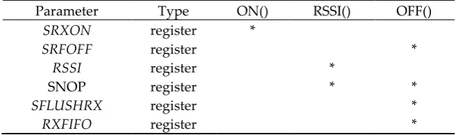
The radio used intheTmote-Sky Platform is CC2420. The CC2420 is an IEEE 802.15.4 compliant RF transceiver 2.4 GHz designed for low-power and low-voltage WSN applications. CC2420 is controlled via SPI port, and a series of digital output and input, as well as interrupts by MSP430. The CC2420 driver in Contiki OS provides two types of radio check, CCA and RSSI. CCA is based on the measured RSSI value and a programmable threshold[35]. The RSSI value is averaged over 8 symbol periods (128 µ s), in accordance with [26]. MCU SPI pin takes strobe commands registers and sends them to CSn Radio pin for calibration. There are types of registers, status bits, and pins for radio control in CC2420 driver in Contiki OS. Table 1 lists the ones which are used in three ON (), RSSI (), and OFF () functions in the course of an idle listening channel check by RSSI according to CC2420.c file available in Contiki OS.
Table 1. Participants in one idle listening based on CC2420 driver source code in Contiki OS.
Parameter Type ON() RSSI() OFF()
SRXON register *
SRFOFF register *
RSSI register *
SNOP register * *
SFLUSHRX register *
RSSI_VALID Status bit *
𝑇𝑋_ACTIVE Status bit *
CSN pin *
FIFOP pin *
3.2. Energest Module
In implementing the proposed method we use the Enegest module feature to configure the application on nodes. Contiki uses the Energest software-based module to estimate the power consumption of the nodes. With this module, time spent for every sensor node is measured in some states such as CPU, LPM, Tx, and Rx in real-time. The energy estimation module is called when the component is turned on to produce a time stamp. The power consumption of nodes is calculated as follows:
𝑃 = 𝑃_𝐶𝑃𝑈 + 𝑃_𝐿𝑃𝑀 + 𝑃_𝑅𝑥 + 𝑃_𝑇𝑥
(1)
The average power consumption of each node (P) is sum of the average power consumption in CPU state (P_CPU) that is activated whenever the node is active (the real-time the CPU is active without using the radio transceiver is CPU −Tx –Rx ), LPM state(P_LPM) that is activated when the sensor node goes to Low Power Mode, Rx state(P_Rx) that node is active in the radio receive mode and Tx state(P_Tx) that radio is active in transmit mode. battery voltage(Vcc) and current power consumption in the indicated state are set based on platform datasheet. In fact, the energy consumption in states is calculated based on the number of CPU ticks based on microcontroller, current power consumption in indicated state and battery voltage [36],[37]. The Tmote-Sky power parameters are considered according to table 2 as follows.
Table 2. The power parameters in Tmote-Sky based on[38]
Unit value
power current consumption state Variable volt 3 Supply voltage VCC mW 1.8
MCU on, Radio off PC_CPU
mW 0.0545
MCU idle, Radio off PC_LPM
mW 17.7
MCU on, Radio Tx PC_Tx
mW 20
MCU on, Radio Rx PC_Rx
3.3. Network scenario
Since the purpose of this paper is not merely to provide a method for simple and one hop networks, the basis of this research is based on a multi-hop random network in order to make the proposed method as practical as possible. In the multi-hoprandom scenario, nodes are exposed to different numbers of neighbors, so interference has a greater impact on nodes. Nodes also have different amounts of RSSI. On the other hand, the network packets are more likely to be lost. In addition, each node experiences a different number of retries in sending packets[39]. Thereforein the
random scenario, the power consumption in the nodes is not monotonous.Figure 1 shows a scenario
Figure 1. The simulation scenario and network graph based on the RPL routing protocol.
3.4. Network Protocols
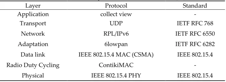
The Network layer protocol’s stack on the nodes list in Table 3 is among the most widely used in WSN. We use the feature of a collect-view application available in Contiki OS to allow data to be aggregated and categorized by a node in the network. It basically involves a sink node and one (or more) sender nodes. Data such as sensor, power,and network information is sent from the sender node to the sink node and the collect-view (a java-based application available in Contiki OS Cooja) displays them in a graphical form [40]. In this work, the IPv6 Routing Protocol for LLNs (RPL) is set as a proactive routing protocol. RPL automatically forms a tree topology by exchanging ICMPv6 control packets to find a path to the root. 6LowPAN (i.e. IPv6 over Low -Power Wireless Personal Area Networks) is an adaptation layer protocol that allows the transport of IPv6 packets over 802.15.4 links. Carrier Sense Multiple Access with Collision Avoidance (CSMA/CA) adopted for Mac layer as the IEEE 802.15.4 standard and finally ContikiMAC are used as the RDC layer for control 802.15.4 radio based on Low Power Listening(LPL). The RDC layer in the sink is set to Null_RDC, so the sink doesnot sleep during network life.
Table 3. Network layers structure used on the nodes[36].
Standard Protocol
Layer
- collect view
Application
IETF RFC 768 UDP
Transport
IETF RFC 6550 RPL/IPv6
Network
IETF RFC 6282 6lowpan
Adaptation
IEEE 802.15.4 IEEE 802.15.4 MAC (CSMA)
Data link
-ContikiMAC
Radio Duty Cycling
IEEE 802.15.4 IEEE 802.15.4 PHY
Physical
4. Problem statement
positioned over minimum interference with other unrelated radio or noise signals
.
2. The node is in a state of coexistence with unrelated radios, noise or interference. In the state 1 between each data reception (positive WakeUp) the node will have a large number of idle listening that plays a significant role in the activity of a radio. In the state 2, in addition to idle listening, the node also has many false WakeUp. Figure 2 shows samples of positive, false and idle listening WakeUp on the Radio Timeline in Cooja. The X and Y axes represent to node numbers and their activity of radio respectively. The red, blue, and green colors in activity of radio line show interference, sending packet and receiving packet respectively[41].Figure 2. Positive, False and Idle listening WakeUp in Cooja timeline.
The ContikiMAC considers CCA_CHECK_TIME that is the time it takes to perform a CCA check. In fact, CCA_CHECK_TIME is a balancing time for other timing parameters in ContikiMAC and it has no direct effect on CCA duration
.
The time spent on each false WakeUp is depending on MAX_NONACTIVITY_PERIODS.It is the maximum number of periods we allow the radio to be turned on without any packet being received. Each period counts as a sum of CCA_CHECK_TIME and CCA_SLEEP_TIME. The CCA_SLEEP_TIME is the time between two successive CCA checks. The time variables in ContikiMAC that affect both idle listening and false WakeUp times are shown in Table 4.
The Fast-Sleep mechanism is responsible for the diagnosis of false WakeUps in ContikiMAC. So If the node fails to receive data after 11 periods (21.1 ms), it quickly returns to sleep mode.
Table 4. The amount of effect on idle listenings and false WakeUps according to ContikiMAC.c
Variable CPU ticks Unit(ms)
CCA_CHECK_TIME 32768/8192 0.4
CCA_SLEEP_TIME (32768/2000) + 1 1.7
MAX_NONACTIVITY_PERIODS 10×( CCA_CHECK_TIME +
CCA_SLEEP_TIME) 21
Table 5 shows the number of idle listenings and false WakeUps during the 10-minute simulation in the 5, 7, 12 nodes according to section 3.3 and 3.4. For example, the time spent in idle listening and false WakeUp in Node7 is calculated as Equation 2. In fact, almost 1.6% of the network time is wasted in idle listening and false WakeUp in Node 7. This is, of course, a mere indication of the effect of the wake-up time loss on idle listenings and WakeUps, and it is not a definite value. Thus except for the positive WakeUps, the node tolerates inefficient energy consumption in idle listenings and false WakeUps. Because this value varies depending on the application and location of the nodes.
Table 5. The number of idle listenings and false WakeUps in nodes 5,7 and 12
Node number Idle listenings False WakeUp
7 13895 220
12 12082 50
𝑇𝑛𝑜𝑑𝑒 7= 𝑇𝑖𝑑𝑙𝑒+ 𝑇𝑓𝑎𝑙𝑠𝑒
𝑇𝑛𝑜𝑑𝑒 7 =
(
13895 × 0.4)
+(
220 × 21)
= 5558 + 4620 = 10178 𝑚𝑠(2)
5. Lightweight clear channel assessment (LW-CCA)
In this paper, we propose the LW-CCA, a lightweight, low-complexity programming method designed to minimize WakeUp power on ContikiMAC nodes. In this method, it attempts to reduce the time spent in Rx mode by maintaining a PDR rate similar to base ContikiMAC. By focusing on software and hardware RSSI status check time, LW-CCA reduces the percentage of Duty cycles as
much as possible to reduce radio power consumption.The minimum WakeUp time for a medium
check would take at least one idle listening. In section 5.1, a single idle listening is analyzed to identify the essential time factors. Furthermore, the evaluation of the minimum and maximum RSSI status check time on nodes is presented in section 5.2. In section 5.3, the LW-CCA node categories RSSI based on the CCA verification, whether they are predicted as a false WakeUp, idle listening, or positive WakeUp. Finally, in section 5.4, the performance of LW-CCA for the classification and validation of RSSI and the dynamic radio check time are described. Worth mentioning that LW-CCA runs exclusively on the relay and sender node, not sink or server node. The proposed method is considered when the nodes are fixed in the network. The following sections describe the details of the proposed method.
5.1. the time factors in a single RSSI radio check
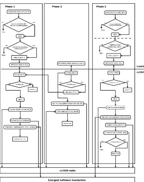
The basis of LW-CCA is the momentary check of RSSI. In this study, we examine the time parameters involved in an RSSI radio check. The relationship between ContikiMAC functions, the CC2420 driver and the Energest module is shown in Figure 3. In general, each RSSI radio check consists of three phases:
Phase 1: Checking permissions for radio driver access by RDC, registering radio hardware to Rx mode by the radio driver and recording start time of Rx by Energest.
Phase 2: Validating the RSSI and returning RSSI value from related radio register.
Phase 3: Set the radio registers to Off state, Preparing the radio queue for the next stage of radio activity and also announce the end of Rx state to Energest module.
Figure 3. Diagram of the relationship between RDC, the radio driver and the Energest module in performing a single RSSI.
𝑇𝛥=
RTIMER_SECOND
10 =
32768
10 = 3276 (3)
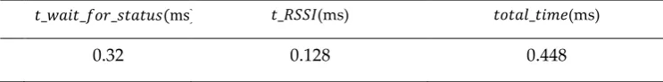
Table 6 shows time factors which are resulted from analyzing the relationship between RDC and radio hardware in an RSSI check. The table is extracted from the radio Timeline in Cooja.
Table 6. Effective time factors per idle listening based onRSSI under Cooja simulator Timeline
𝑡_𝑤𝑎𝑖𝑡_𝑓𝑜𝑟_𝑠𝑡𝑎𝑡𝑢𝑠(ms) 𝑡_𝑅𝑆𝑆𝐼(ms) 𝑡𝑜𝑡𝑎𝑙_𝑡𝑖𝑚𝑒(ms)
0.32 0.128 0.448
Every RSSI check involves the different action timings:. t_wait_for_status is time spent for RSSI status check based on equation 3. t_RSSI is time spent for the read of RSSI status check. Total_time is the sum of the time spent in an RSSI radio check. Actually in an RSSI check, the 𝑡_𝑤𝑎𝑖𝑡_𝑓𝑜𝑟_𝑠𝑡𝑎𝑡𝑢𝑠 takes the longest time 0.32 milliseconds (20 symbols period according to[42]) to doing a reliable RSSI status check-in ContikiMAC. So it indicates that ContikiMAC devotes more time to RSSI status check than 8 symbols periods suggested in CC2420 datasheet. It should be noted that 20 Symbols has no role in RSSI reception. In fact, it is a BackOFF for reliable time to wake the radio.
5.2 The RSSI check time models in LW-CCA
This section examines the hardware and software RSSI status check time.Based on the phase 2 section 5.1, LW-CCA divides the radio check time into 𝑇𝛥 and t_RSSI time periods. The following function is responsible for doing the RSSI validation under a period of time t_RSSI=0.128 ms (8 symbols) and 𝑇𝛥 = 0.32 ms (20 symbols) in cc2420.c.
static void
wait_for_status(uint8_t status_bit) {
rtimer_clock_t t0; t0 = RTIMER_NOW();
while(!(get_status() & status_bit)
&& RTIMER_CLOCK_LT(RTIMER_NOW(), t+ RTIMER_SECOND / 10);
}
The LW-CCA, with respect to radio check time partition, considers two models for a dynamic check in the Rx
mode.
Model 1: This model considers RSSI check for measuring signal strength in Rx and uses default CCA check-in Tx mode. The RSSI status check time is by default method in CC2420 driver based on the sum of 𝑇𝛥 and t_RSSI.
Model 2: In this model, considering𝑇𝛥= 0, the RSSI check time is considered to be equal with the 8 symbols period’s case. In fact, the RSSI status check is performed over the intended time for the cc2420 radio chip. The rest of the conditions are the same as in model 1.The following function is responsible for doing the RSSI validation under a period of time t_RSSI=0.128 ms.
static void
rtimer_clock_t t0; t0 = RTIMER_NOW();
while(!(get_status() & status_bit)
&& RTIMER_CLOCK_LT(RTIMER_NOW(), t0); }
Figure 5. The rssi check time with 0.128 ms (8 symbols periods) by ignoring 𝑇𝛥 and relation source
code in cc2420.c.
Table 7 shows a comparison between indicated models in terms of percentage of the listening duty cycle according to the scenario in section 3.3 and 3.4 in a 40 minute (High Rate). It shows that ignoring 𝑇𝛥 in RSSI
status check time for nodes based on model 2 results in about 11 percentage reduction in average of the listening duty cycle. The results in Table 7 are extracted based on the Collect-View output. The details of the average listen duty cycle calculation are available in section 6.
Table 7. Comparison of models of 1 and 2 in terms of percentage of listen Duty-Cycle.
Method Rx| Tx Listen Duty-Cycle (%)
Model 1 RSSI | CCA 1.451
Model 2 RSSI | CCA 1.282
Therefore, each RSSI status check can be divided into two states: 8 internal symbols set for CC2420 radio hardware and 20 symbols for performing a reliable radio WakeUp on Rtimer equal to Equation 3. In fact, 8 and 20 symbols can be considered as the minimum and maximum periods required to perform a minimum radio check time, respectively. Figure 6 illustrates the performance of the RSSI status check. The file Msp802154Radio.java in Cooja is responsible for simulating 8 symbols for RSSI status check based on CC2420 radio datasheets.
Figure 4. The performance of RSSI status checks based on Radio hardware and ContikiMAC.
Figure 5. Model 1: RSSI check in Rx(28 symbols) and Tx(28 symbols) in Cooja Timeline.
Figure 6. Model 2: RSSI check-in Rx (8 symbols) and Tx (28 symbols) in Cooja Timeline.
5.3. Categories of RSSIs in LW-CCA
The CC2420 in our application returns [-100, 0] as the normal range of RSSI, where -100 is the minimum level of the noise floor. In performing each RSSI check, the values obtained for RSSI can be divided into three categories: Firstly, the values that are valid and determine the radio activity and ultimately, it results in the receipt of the data frame (positive WakeUP); Secondly, the values that are valid and determine the radio activity and ultimately, it results in the noise or interference (false WakeUp); and third the values that are invalid and do not specify any activity on the radio(idle listening). In the LW-CCA categories, false WakeUp and Idle listening RSSIsare located in rssi_null. Figure 7 shows the RSSIs classified. Identification of idle listening and false WakeUp conducted via CC2420 driver’s and ContikiMAC’s side and the false WakeUp is reported to CC2420 driver through NETSTACK_RADIO[43].
Figure 7. RSSIs classified as Null.
5.4. The dynamic RSSI check time in LW-CCA
This section describes the performance of LW-CCA according to the description of the previous sections. As mentioned, LW-CCA performance is based on RSSI measurements. In this method, for a dynamic check, the radio check time works according to the models 1 and 2 (section 5.2. ). Every node has two tasks in receiving RSSIs : i.e., receiving RSSI based on model 1, and re-evaluating RSSI based on the model 2 and its classification:
The following proposed method is illustrated in Figure 8.
Nodes perform radio checks in two modes: listen and transmit mode. In the LW-CCA method, a reduction in Rx radio check time is considered. Each ContikiMAC node periodically checks the radio with CCA pairs. In fact, each CCA recognizes the validity and invalidity of radio activity by comparing the RSSI threshold. Based on Section 5.1, in LW-CCA each radio check uses the RSSI directly. LW-CCA nodes first assign a value of 8 symbols (Model 2) to the status check RSSI. The value obtained is evaluated based on the classification in Section 5.3. In this case, two states are considered:
RSSI is a member of rssi_null list:
If the RSSI value is a member of the rssi_null list, the node returns 1 to ContikiMAC and quickly go to sleep. In fact, the node does just 8 Symbols RSSI status check.
RSSI is a member of the rssi_active List or it is anew RSSI:
If the RSSI value is outside the rssi_null list, it is either a new value or a member of rssi_active. In both cases, the node re-evaluates the radio based on Model 1. In this case, after the RSSI check, the CCA check will be considered for validation and classification of RSSI. If CCA returns a value of 1, the RSSI value is detected as an idle listening and stored as a worthless value in the rssi_null list. Otherwise, ContikiMAC applies its timing based on Section 4 to check for false Wake Up or positive WakeUp. If the radio activity in the node results in a false WakeUp the RSSI value is stored in the rssi_null list and the node goes to sleep quickly based on the Fast-Sleep mechanism. If the RSSI results in positive Wake Up the node stays on the receiving mode.
Figure 8. The diagram of the LW-CCA method.
The proposed method actually uses the maximum value of the RSSI status check time when the RSSI value is detected either new or active. Therefore, in other cases at least 8 symbols are considered. LW-CCA thus reduces the amount of radio check-in false WakeUps and idle listening as much as possible to reduces the inefficient power consumption caused by radio activity in Rx mode. Also, using RSSI validation based on the CCA value makes the node performance reliable in the real environment as well.
We evaluated the proposed method LW-CCA and compared it with ContikiMAC using the Cooja simulator.Tmote-Sky is used as a hardware platform for nodes on the network. The network protocol for all nodes is the same as in Table 3. Figure 1illustrates the network scenario with respect to the RPL routing protocol graph. It is a random scenario with a variety of hops and neighbors consists of:
One emulated node that is programmed as a sink that plays the role of the root node for RPL in the network graph. In fact, it is a UDP server that collects data from client nodes;
21 emulated duty cycle nodes as UDP clients in network graph that send data to sink ;
The power consumption of the nodes is estimated by the Energest module available at Contiki.
The LW-CCA method is compared with the ContikiMAC in terms of the average CPU ticks in CPU, LPM, Rx and Tx, CPU Power, LPM Power, Rx and Tx Duty-Cycle(%), Rx and Tx Power, Total Power consumption and PDR. LW-CCA and ContikiMAC nodes are evaluated based on the two data transmission rates, once every 60 seconds (Low Rate) and once every 30 seconds (High Rate). Simulation time for each of Low rate and High rate scenario is 4 hours. The node number “1” is considered as a sink and its radio is turnedon during the network time, so the network status analysis is done based on the sender nodes from 2 to 21. All of the scenarios outputs are based on Collect-View in Cooja. The equations are based on embedded equations for power consumption in the Collect-View source code [31]. The power parameters for simulation are listed in Table 2.
6.1. The average of ticks in CPU, LPM, Rx, and Tx states in the network
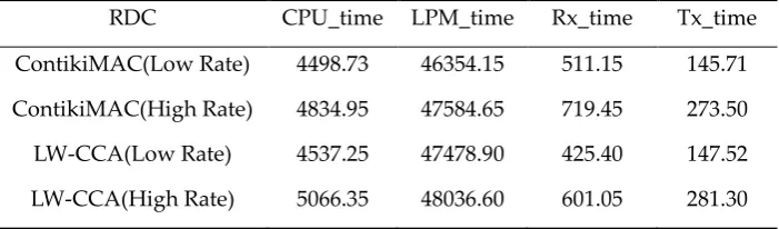
Tick conversion simply refers to the ability to convert physical units to timer ticks [44]. On a system with a 2 MHz timer, for example, 1 ms is mapped to 2000 ticks. The calculation of the power consumption in different states for the nodes depends on how long the node stays in every state. The Energest considers the time spent in different states with the number of ticks in that state. Table 8 shows the average of ticks in CPU, LPM, Rx and Tx states in both low rate and high rate scenarios in LW-CCA and ContikiMAC nodes. Table 8 shows the average of ticks for CPU (numbers of ticks for CPU in active mode) in CPU_time, LPM(numbers of ticks in low power mode) in LPM_time, Rx(numbers of ticks in listening mode) in Rx_time and Tx(numbers of ticks in transitionmode) in Tx_time. The LPM _time shows that LW-CCA by reducing RSSI status check time in false WakeUps and idle listenings, increase low power mode time in nodes. CPU_time simulation result shows that there is a small amount of computing overhead in LW-CCA. Rx_time also shows a significant decrease in listening time in LW-CCA, although there is little change in Tx_time. It should be noted that the parameters are averaged from all of the sender nodes.
Table 8. The average of CPU ticks in SKY nodes
RDC CPU_time LPM_time Rx_time Tx_time
ContikiMAC(Low Rate) 4498.73 46354.15 511.15 145.71
ContikiMAC(High Rate) 4834.95 47584.65 719.45 273.50
LW-CCA(Low Rate) 4537.25 47478.90 425.40 147.52
LW-CCA(High Rate) 5066.35 48036.60 601.05 281.30
6.1. Average of Percentage for Listen and Transmit Duty Cycle in the network
ContikiMAC nodes. LW-CCA decreases average of Listen Duty Cycle about 0.2 in both of Low High Send Rate scenarios that It results in a reduction of approximately 18 percent in the average total Listen Duty Cycle.The average percentage of transmit Duty Cycle in LW-CCA doesn't make much difference to ContikiMAC. The experiment results show that the proposed LW-CCA method can reduce the time of Listen Duty Cycle by considering a dynamic RSSI check time so that it tries to reduce listen time in false WakeUps and idle listenings. How to calculate the average percentage of Listen and transmit Duty Cycle is according to Equations 4 and 5. Rx_time, Tx_time, CPU_time and LPM_time are equal with numbers of ticks available in Table 8.
Rx DutyCycle(%) = 100 ∗ ( Rx_time
CPU_time + LPM_time) (4)
Tx DutyCycle(%) = 100 ∗ ( Tx_time
CPU_time + LPM_time) (5)
Table 9. The average of Rx and Tx DutyCycle(%)
RDC Rx DutyCycle(%) Tx DutyCycle(%)
ContikiMAC(Low Rate) 1.005 0.286
ContikiMAC(High Rate) 1.372 0.521
LW-CCA(Low Rate) 0.817 0.283
LW-CCA(High Rate) 1.131 0.529
6.2. Network Power Consumption
The total power consumption of each node comprises the power consumption of the node in different states such as CPU, LPM, Rx, and Tx. In this section, the average power consumption on indicated states in LW-CCA nodes is compared with the ContikiMAC nodes in both low and high rate scenarios and evaluates the effect of the proposed method on the total power consumption and finally the Packet delivery rate (PDR). The power and time parameters in the power consumption calculation are obtained from Tables 2 and 8. The average of power consumption in CPU, LPM, Rx and Tx states in network is calculated by Equations 6, 7, 8 and 9 respectively. The average of total power consumption (P) is calculated according to Equation 1. For example, average of listen power for LW-CCA nodes in high rate is calculated in Equation 10.
P_CPU(mW) =CPU_time × VCC × PC_CPU
CPU_time + LPM_time (6)
P_LPM(mW) =LPM_time × VCC × PC_LPM
CPU_time + LPM_time (7)
P_Rx(mW) =Rx_time × VCC × PC_Rx
CPU_time + LPM_time (8)
P_Tx(mW) =Tx_time × VCC × PC_Tx
CPU_time + LPM_time (9)
P_Rx(LW − CCA, High_Rate) =Rx_time × VCC × PC_Rx CPU_Time + LPM_time =
601.5 × 3 × 20
5066.35 + 48036.60= 0.679(mW) (10)
Table 10 compares the network states in terms of average power consumption for LW-CCA and ContikiMAC in CPU, LPM, Rx, Tx states, and finally considers the average total power consumption and packet delivery rates. The outputs show that the average power consumption in the LPM mode for both methods is relatively similar. The average power consumption in the high-rate scenario in the LW-CCA represents a relatively higher value in CPU state, which may be due to the processing overhead imposed on the CPU in the LW-CCA. But the reduction in average power consumption in the listening state and finally, the overall average energy consumption in LW-CCA nodes justify this overhead. The LW-CCA is able to reduce average listening power by 0.113 and 0.144 mW in low and high rates, respectively. The average power consumed in the transmit state in both methods shows a relatively similar value. Finally, the overall average power consumption in LW-CCA nodes has decreased by 0.121 and 0.124 mW in low and high rates, respectively compared to ContikiMAC. Table 10 shows that LW-CCA is able to retain a 99% packet delivery rate similar to ContikiMAC by decreasing overall power consumption by 7.1% and 8.7% for high and low rate scenarios, respectively.
Table 10. The average of power consumption in CPU, LPM, Rx, Tx , total power consumption and PDR
RDC P_CPU(mW) P_LPM(mW) P_Rx(mW) P_Tx(mW) P(mW) PDR(%)
ContikiMAC(Low Rate) 0.477 0.149 0.603 0.152 1.381 99
ContikiMAC(High Rate) 0.498 0.148 0.823 0.277 1.746 99
LW-CCA(Low Rate) 0.471 0.149 0.490 0.150 1.260 99
LW-CCA(High Rate) 0.515 0.147 0.679 0.281 1.622 99
7. Conclusions
about 8% reduction in the overall average power consumption in the nodes. LW-CCA reduces energy consumption while it maintains packet delivery rate 99%, which is the same as ContikiMAC in sender nodes. The proposed method can be applied to all IoT platforms based on 802.15.4 radios such as Z1, Tmote-SKY, and Micaz [29]. Since RSSI validation is based on CCA check, therefore it can also be exploited in the real environment. The instantaneous categorization mechanism in the LW-CCA method can make this method flexible against interference caused by irrelevant radios or noise.
Acknowledgments
We acknowledge the support of the German Research Foundation (DFG) and the Bauhaus-Universität Weimar within the Open-Access Publishing Programme.
Conflicts of Interest
The authors declare no conflict of interest.
Author Contributions
Conceptualization, modeling, data curation, data analysis, and analysis of results, M.A.N, S.S., A.T.C., A.M., and N.N.; IoT, machine learning and soft computing expertise, M.A.N, S.S., A.T.C., A.M., and N.N.; mathematics expertise, M.A.N, S.S., A.T.C., A.M., and N.N.; management, database, writing, administration, and methodology M.A.N, S.S., A.T.C., A.M., and N.N.; visualization, M.A.N, S.S., A.T.C., A.M., and N.N.; supervision, resources, software, revision, and verification of the results, A.T.C., A.M., and S.S., funding, A.M.
Abbreviations
Abbreviation Definition
CCA Clear Channel Assessments
CPU Central Processing Unit
CSMA Carrier Sense Multiple Access with Collision Avoidance
IoT Internet of Things
LPL Low Power Listening
LPM Low Power Mode
LW-CCA Light weight CCA
MAC Medium Access Control
MCU Microcontroller Unit
PDR Packet Delivery Rate
RDC Radio DutyCycle
RPL Routing Protocol for LLNs
RSSI Received Signal Strength Indicator
UDP User Datagram Protocol
VCC voltage at the common collector
WSN Wireless Sensor Network
References
[1] S. Avallone, S. Guadagno, D. Emma, A. Pescapè, and G. Ventre, “D-ITG distributed internet traffic generator,” Proc. - First Int. Conf. Quant. Eval. Syst. QEST 2004, no. ii, pp. 316–317, 2004.
[2] P. Dutta and A. Dunkels, “Operating systems and network protocols for wireless sensor networks,”
Philos. Trans. R. Soc. A Math. Phys. Eng. Sci., vol. 370, no. 1958, pp. 68–84, 2012.
in the Internet of Things,” Sensors, vol. 19, no. 14. MDPI, 2019.
[4] V. C. Thang, “A Comparative Study of Network Performance between ContikiMAC and XMAC Protocols in Data Collection Application with ContikiRPL,” Int. J. Comput. Netw. Inf. Secur., vol. 11, no. 8, p. 32, 2019.
[5] J. Bhar, “A Mac Protocol Implementation for Wireless Sensor Network,” J. Comput. Networks Commun., vol. 2015, pp. 1–12, 2015.
[6] M. Sha, G. Hackmann, and C. Lu, “Energy-efficient Low Power Listening for Wireless Sensor Networks in Noisy Environments,” Proc. 12th Int. Conf. Inf. Process. Sens. Networks, vol. 61, pp. 277–288, 2013. [7] X. Zheng, Z. Cao, J. Wang, Y. He, and Y. Liu, “Interference resilient duty cycling for sensor networks
under co-existing environments,” IEEE Trans. Commun., vol. 65, no. 7, pp. 2971–2984, 2017.
[8] Y. Huang, W. XIANG, S. WEN, and Y. JIN, “The Study of Traffic-Aware ContikiMAC,” DEStech Trans.
Comput. Sci. Eng., no. wcne, 2016.
[9] F. A. Aoudia, M. Magno, M. Gautier, O. Berder, and L. Benini, “Wake-up receivers for energy efficient and low latency communication,” in Proceedings of the 15th International Conference on Information
Processing in Sensor Networks, 2016, p. 53.
[10] M. Magno, F. A. Aoudia, M. Gautier, O. Berder, and L. Benini, “WULoRa: An energy efficient IoT end-node for energy harvesting and heterogeneous communication,” Proc. 2017 Des. Autom. Test Eur. DATE
2017, pp. 1528–1533, 2017.
[11] M. M. D. Khomami, A. Rezvanian, and M. R. Meybodi, “A new cellular learning automata-based algorithm for community detection in complex social networks,” J. Comput. Sci., vol. 24, pp. 413–426, 2018.
[12] S. Basagni, “CTP-WUR : The Collection Tree Protocol in Wake-up Radio WSNs for Critical Applications,” in 2016 International Conference on Computing, Networking and Communications (ICNC), 2016, pp. 0–5.
[13] C. Guo, L. C. Zhong, and J. M. Rabaey, “Low power distributed MAC for ad hoc sensor radio networks,” in GLOBECOM’01. IEEE Global Telecommunications Conference (Cat. No. 01CH37270), 2001, vol. 5, pp. 2944–2948.
[14] S. Mahlknecht and M. S. Durante, “WUR-MAC: energy efficient wakeup receiver based MAC protocol,”
IFAC Proc. Vol., vol. 42, no. 3, pp. 79–83, 2009.
[15] G. P. Joshi, S. Y. Nam, and S. W. Kim, “Cognitive radio wireless sensor networks: applications, challenges and research trends,” Sensors, vol. 13, no. 9, pp. 11196–11228, 2013.
[16] F. Sutton, B. Buchli, J. Beutel, and L. Thiele, “Zippy: On-demand network flooding,” in Proceedings of the
13th ACM Conference on Embedded Networked Sensor Systems, 2015, pp. 45–58.
[17] F. Dressler et al., “Protocol design for ultra-low power wake-up systems for tracking bats in the wild,”
IEEE Int. Conf. Commun., vol. 2015-Septe, no. Section III, pp. 6345–6350, 2015.
[18] S. Rayanchu, A. Patro, and S. Banerjee, “Airshark: Detecting non-WiFi RF Devices Using Commodity WiFi Hardware,” Proc. 2011 ACM SIGCOMM Conf. Internet Meas. Conf., pp. 137–154, 2011.
[19] S. Rayanchu, A. Patro, and S. Banerjee, “Catching Whales and Minnows using Wifinet: Deconstructing Non-wifi Interference using Wifi Hardware,” USENIX Conf. Networked Syst. Des. Implement., pp. 57–70, 2012.
[20] S. Hong and S. Katti, “DOF: A Local Wireless Information Plane,” Sigcomm 2011, pp. 230–241, 2013. [21] K. R. Chowdhury and I. F. Akyildiz, “Interferer classification, channel selection and transmission
[22] B. Bloessl, S. Joerer, F. Mauroner, F. Dressler, and S. Joerer, “ACM MobiCom 2012 Poster : Low-Cost Interferer Detection and Classification using TelosB Sensor Motes,” Proc. 18th Annu. Int. Conf. Mob.
Comput. Netw., vol. 16, no. 4, pp. 403–406, 2012.
[23] R. Zhou, Y. Xiong, G. Xing, L. Sun, and J. Ma, “ZiFi: wireless LAN discovery via ZigBee interference signatures,” in MobiCom ’10 Proceedings of the sixteenth annual international conference on Mobile computing
and networking, 2010, pp. 49–60.
[24] F. Hermans and E. Ngai, “SoNIC : Classifying Interference in 802 . 15 . 4 Sensor Networks,” in ACM, 2013, pp. 55–66.
[25] A. King and U. Roedig, “Differentiating Clear Channel Assessment Using Transmit Power Variation,”
ACM Trans. Sens. Networks, vol. 14, no. 2, pp. 1–28, 2018.
[26] M. P. Uwase, M. Bezunartea, J. Tiberghien, J. M. Dricot, and K. Steenhaut, “Experimental Comparison of Radio Duty Cycling Protocols for Wireless Sensor Networks,” IEEE Sens. J., vol. 17, no. 19, pp. 6474– 6482, 2017.
[27] X. Zheng, Z. Cao, J. Wang, Y. He, and Y. Liu, “ZiSense: Towards Interference Resilient Duty Cycling in Wireless Sensor Networks,” Sensys’14, pp. 119–133, 2014.
[28] J. Oller, I. Demirkol, J. Casademont, J. Paradells, G. U. Gamm, and L. Reindl, “Has Time Come to Switch from Duty-Cycled MAC Protocols to Wake-Up Radio for Wireless Sensor Networks?,” IEEE/ACM Trans.
Netw., vol. 24, no. 2, pp. 674–687, 2016.
[29] M. O. Ojo, S. Member, S. Giordano, S. Member, G. Procissi, and I. N. Seitanidis, “A Review of Low-End , Middle-End , and High-End Iot Devices,” IEEE Access, vol. 6, pp. 70528–70554, 2019.
[30] M. Joshi and B. Kaur, “Web Integrated Smart Home Infrastructure Using Internet of Things,” Int. J. Eng.
Res. Gen. Sci., vol. 3, no. 6, pp. 153–158, 2015.
[31] A. Velinov and A. Mileva, “Running and Testing Applications for Contiki OS Using Cooja Simulator,”
Int. Conf. Inf. Technol. Dev. Educ., pp. 279–285, 2016.
[32] S. Sadiki, M. Ramadany, M. Faccio, D. Amegouz, and S. Boutahari, “Running Smart Monitoring Maintenance Application Using Cooja Simulator,” in International Journal of Engineering Research in
Africa, 2019, vol. 42, pp. 149–159.
[33] T. Instruments and I. Slas, “MSP430F15x, MSP430F16x, MSP430F161x MIXED SIGNAL MICROCONTROLLER,” Office, no. October 2002. p. 77, 2011.
[34] M. Nasseri, H. Al-Olimat, M. Alam, J. Kim, R. Green, and W. Cheng, “Contiki Cooja Simulation for Time Bounded Localization in Wireless Sensor Network,” Proc. 18th Symp. Commun. Netw., pp. 1–7, 2015. [35] P. Description and K. Features, “SmartRF ® CC2420,” 2004.
[36] J. Schandy, L. Steinfeld, and F. Silveira, “Average power consumption breakdown of Wireless Sensor Network nodes using IPv6 over LLNs,” in 2015 International Conference on Distributed Computing in Sensor
Systems, 2015, no. June, pp. 242–247.
[37] N. M. Son, T. N. Thinh, N. D. Thi, N. C. Nhan, and I. Technology, “An Approach of Low Power Wifi Sensor Mote for Internet of Things Applications Faculty of Computer Engineering , Faculty of Computer Science and Engineering , Corresponding Author : Nguyen Minh Son,” vol. 7, no. 4, pp. 161–166, 2016. [38] SNM, “Tmote Sky sensor datasheet,” pp. 1–28, 2007.
[39] M. Michel and B. Quoitin, “Technical Report : ContikiMAC vs X-MAC performance analysis,” Netw.
Internet Archit., vol. 5, pp. 1–28, Apr. 2015.
Systems, 2013, p. 70.
[41] F. Ö sterlind, J. Eriksson, and A. Dunkels, “Cooja TimeLine: a power visualizer for sensor network simulation,” in Proceedings of the 8th ACM Conference on Embedded Networked Sensor Systems, 2010, pp. 385–386.
[42] T. C. O. S. O. for the I. of T. Dunkels, Adam(Member of The Contiki Open Source OS for the Internet of Things), Simon Duquennoy(Member of Contiki-NG, “Contiki OS,” 2015. [Online]. Available: https://github.com/contiki-os/contiki/blob/master/dev/cc2420/cc2420.c.
[43] Y. Quan, “Topology-based Device Self-identification in Wireless Mesh Networks,” School of Electrical Engineering and Computer Science, STOCKHOLM, SWEDEN, 2019.
[44] E. Baccelli et al., “RIOT: An open source operating system for low-end embedded devices in the IoT,”
![Table 2. The power parameters in Tmote-Sky based on[38]](https://thumb-us.123doks.com/thumbv2/123dok_us/7932387.1317106/5.595.77.521.443.540/table-power-parameters-tmote-sky-based.webp)