Thermal energy storage for CSP
(Concentrating Solar Power)
Xavier Py(∗), Najim Sadiki, R´egis Olives, Vincent Goetz andQuentin Falcoz
Laboratoire PROc´ed´es Mat´eriaux et Energie Solaire PROMES-CNRS UPR 8521 University of Perpignan - Via Domitia, Perpignan, France
Summary. — The major advantage of concentrating solar power before photo-voltaic is the possibility to store thermal energy at large scale allowing dispatchabil-ity. Then, only CSP solar power plants including thermal storage can be operated 24 h/day using exclusively the solar resource. Nevertheless, due to a too low avail-ability in mined nitrate salts, the actual mature technology of the two tanks molten salts cannot be applied to achieve the expected international share in the power production for 2050. Then alternative storage materials are under studies such as natural rocks and recycled ceramics made from industrial wastes. The present paper is a review of those alternative approaches.
1. – General context
The so-called energy transition is based on a worldwide extended growing of renewable energies. This concerns all kinds of renewable energies leading to local mix adapted to the local resources and needs. According to the fact that almost all renewable energies
present major intermittencies (especially solar and wind energies) and mismatch with the consumers needs, numerous energy storage units will be also highly needed.
Then, among the major issues associated to the energy transition, the question of the availability in mineral resources to build all the corresponding energy processes and energy storage facilities could lead to major bottlenecks. More generally, the LCA (life cycle analysis) should be addressed properly for each involved process to assess its en-vironmental and energetic benefits and corresponding enen-vironmental paybacks. This concerns the embodied energy, the green house gas, the water and ecotoxicity impacts, the risks in conflict of use, etc.
Surprisingly, even for the renewable energies technologies developed for almost half a century, their associated LCA are very recent and still scarce. Very often, those technolo-gies are viewed as just usual industrial facilities while their contribution to a sustainable development has to be addressed not only in terms of economy but also in terms of environment and social benefits.
The present paper is focused on the particular case of thermal energy storage (TES) materials for concentrating solar power (CSP) as an illustration of the above more general concern.
2. – CSP technologies
The production of power from the solar radiation is currently achieved by two very different routes: 1) the very popular photovoltaic technique allowing the conversion of the whole solar radiation directly into electricity and 2) the less known thermal route based on a first conversion of the solar radiation (only the direct fraction) to heat to produce steam which is turbined such as in all other thermal power plant [1].
The major advantage of the second one is the fact that it is much easier and more affordable to store the energy at large scale in the form of heat than in the form of electricity. Therefore, the photovoltaic power stations produce rather erratic electricity to the grid inducing major risks of stability and the corresponding economic value of the product is necessarily low. In comparison, thanks to large scale thermal storage, solar thermal power plants can produce 24 h/day very stable power levels to the grid such as all kinds of other thermal power plants. This is the case of Gemasolar (Spain 2011) or Crescent dune (USA 2015) solar power plants implemented recently which are able, thanks to 15 h of TES capacity, to produce 20 and 110 MW of constant power to the grid, respectively.
Other CSP plants such as ANDASOL have less extended TES units, here 7.5 h of capacity, allowing already the possibility to balance properly the solar radiation variation daily. Their production can be easily extended to the night by using fossil backup. Other CSP plants such as the historic CEGS (USA), ran for decades without storage and using only fossil backup.
Fig. 1. – Linear concentrating techno of solar trough.
Fig. 2. – Central receiver concentrating techno.
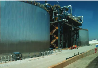
Fig. 4. – Two-tank molten salt TES for CSP.
(those last ones are more devoted to remote areas, small or medium range of power and do not include TES). The former ones operate up to 400◦C while the second ones operate currently up to 800◦C and could even work at higher temperature (they are still limited to the availability of high-temperature materials).
3. – Current thermal storage for CSP
Up to date, all the TES sub-units of industrial CSP plants devoted to several hours of production are based on a unique technology initially developed in Themis-France. This technology [2], the so-called “two-tank molten salt” one (fig. 4), is composed of two separated tanks in which all the molten salt (in all cases a mixture of nitrate salts) used simultaneously as heat transfer fluid (HTF) and thermal storage material can be stored at the two temperature levels. The molten salt stores the thermal energy by change of its temperature, the so-called sensible heat approach. During the sunniest hours of the day, the intentionally over-scaled solar field of the plant delivers a heat power shared between the power block and the TES unit. During the period of time during which the output heat power from the solar field is lower than the nominal feeding power of the power block, the TES unit contribute to balance it. Therefore, using the TES unit, the power block of the plant is fed at nominal power and delivers a constant electric power to the grid. This approach allows also to reduce the maintenance cost of the power block and to increase its life time expectancy.
In this process, the salt has to be kept under liquid state only. As the basic binary eutectic “solar salt” made of NaNO3 and KNO3presents a solidification temperature of 250◦C, the different equipments have to be maintained above this critical temperature to avoid any plug. Soon during the eighties, major efforts were done to find other molten salt mixtures of lower solidification temperature. It was the case in Themis in which a mixture of NaNO2/KNO3/NaNO3 with a solidification temperature of 142◦C was used. This issue is still under study and other mixtures are proposed in the literature.
over the coldest fraction. In this “thermocline” approach [3], the two temperature levels are naturally separated by the difference in density. Its major advantage is to reduce the overall cost of the TES unit (by about 30%) by using a single tank. Nevertheless, heat transfer by diffusion at the interface between the two temperature levels reduces the thermal efficiency. During the charging period, the coldest salt fraction is pumped at the bottom of the tank to be heated by the solar field through a heat exchanger and to go back to the top of the TES tank. During the discharge step, the hottest salt fraction is pumped at the top of the tank to feed the power block and the resulting coldest salt is fed back at the bottom of the tank. Therefore, during those two oper-ating steps, the thermal gradient zone of the salt in the tank moves up (under charge) and down (during the discharge). Efforts are made to develop floating insulating mem-branes of intermediate density following the thermocline during the charge/discharge periods.
Few experiences have been made to use thermal oil as HTF and TES material (SEGS-1 USA) associated to a mixture of granite gravel and sand as filler (to reduce the needed amount of oil in the tank). Unfortunately, this storage unit was destroyed by a major fire inducing a critical environmental impact and a significant societal traumatism. This attempt was the first and last industrial oil-based TES in a CSP plant.
The above TES technology for CSP developed during the eighties for the pilot plant central receiver approach (Themis France and Solar-Two USA) has been used as standard TES system in all industrial CSP plants built from the beginning of the 21st century. This is particularly the case of solar trough CSP plants acknowledged at this time as the most mature CSP approach (but without integrated TES sub-system) to which the mature TES unit of central receiver CSP plants has been added. The hybrid result is illustrated by the ANDASOL (2009, 50 MWe, 7.5 h of TES, Granada Spain) plant which can be considered today as a standard of the technology. More recently, central receiver industrial plants of Gemasolar (2011, 20 MWe, Spain) and Crescent-Dune (2015, 110 MWe, USA) offer 24 h/day of solar only operation at constant power due to their 15 h of TES capacity.
4. – Major limitations and opportunities
The two-tank molten salt approach described in sect.3can be considered as mature and presents actually almost all the expected performances. Nevertheless, this TES technology applied to the worldwide CSP growing is not sustainable.
A first aspect which has been considered only very recently (surprisingly for a tech-nology developed during the eighties) is the environmental impact of the approach. The first complete LCA (Life Cycle Analysis) of CSP solar trough plant including the TES unit has been published in 2011 [4]. This very detailed study highlights the fact that the current TES technology represents 19.3% of the GHG (green house gas) and 18% of the CED (cumulative energy demand) contents of the ANDASOL-like plant.
Therefore, the economical and environmental contributions of the TES unit (which is of 7.5 h of capacity in those studies while 24 h/day running CSP plants involve 15 h of TES capacity) are very significant and their reduction can be already considered as strategic.
Another major concern is the availability of the involved nitrate salts. According to the IEA analysis, the expected 10% of CSP power contribution in the worldwide electricity production in 2050 could induce major tension and even conflict of use in the mineral materials markets. The deep analysis of the mineral resources involved in a CSP plant equipments highlights the fact that only the nitrate molten salt should present major concern in term of availability [5, 6].
Currently, the nitrate salts NaNO3 and KNO3 of the TES for CSP are mainly (at about 60%) natural products mined in North Chile, the other part is from the chemical industry. Even if the major part of this solar salt is a natural mineral material, it presents a significant environmental footprint due to the mine extraction, purification, shipping, implementation in TES. In terms of availability, Chile provides historically salts from the mid of the 19th century with a peak of production at the first world war at a rate of about 3 Mt/y. Due to the needs in nitrates for the war industry, Germans built at that time the industrial synthetic way to produce nitrate salts, inducing a major destabilization in the worldwide market. Today, Chile produces about 0.8 Mt/y of nitrate salts for a market shared between the agriculture (as fertilizer) and the chemical industry. According to the fact that the CSP grow needed to achieve the 10% expected share in the worldwide electricity production of 2015 corresponds to a need in nitrate salts of about 20 Mt/y, this current availability is critically too low. Moreover, the use of the nitrate salts to produce electricity could not be considered as a priority before the agriculture.
Therefore, there is a critical need in alternative HTF and TES materials to achieve the expected CSP grow of the next decades.
5. – Alternative approaches
About one decade ago, the worldwide CSP academic and industrial community has identified the lack of availability and the environmental footprint of the nitrate salts. From this time, major efforts have been made to find alternative technologies based on two major approaches: one trying to reduce the amount of salts of the current processes, the other one trying to develop new technologies without salts.
responsible for this Cp increase are still not fully understood and the transfer of this approach to the industrial scale will have to be addressed also. Nevertheless, this new subject opens a new route to reduce the needs in molten salt juts by increasing their effective performances.
The other way to overcome the lack of nitrates availability is to switch to other HTF and TES materials. This is for instance the case of the proposed CSP central receiver tower plants in which hot air is used as HTF and sand or rock or high-temperature ce-ramics as TES materials. Those promising approaches are still under pilot development.
5.1. Natural materials. – Natural materials to be used as TES materials have been considered from a long time. Already during the Paleolithic, men had to optimize their main heating technology of fire place. In some cases they had only fast fuels available (like straw) and simultaneously needs of long cooking durations. Academics have found evi-dence of use of rocks as TES materials to store heat of straw or other fast-burning fuel for subsequent cooking on the heated rocks. Others were confronted to the incompatibility between fire and water to produce steam (which is obvious for us but was certainly less obvious at the beginning of the fire domestication). They developed an iterative and then very smart technique: rocks were heated in a fire place to be soaked in a water pool next to the fire place and when the rock was cooled down it was moved back to the fire place, etc., and the process reproduced up to the boiling of the water volume.
Still during the Paleolithic, flint stones were used to produce cutting tools. If the corresponding technique of flint stone shaping is well known, the fact that some flint stones were intentionally heated for an easier shaping is less known today. Actually, some flint stones are difficult and even impossible to shape while after controlled heat treatment the transformation is possible and the final product very valuable. As a direct flint heating on a fire place induces an irremediable breaking of the piece, men had to develop very sophisticated techniques to allow a uniform heat treatment in the stone volume. Today, this knowledge has been lots but the observed remaining tools demonstrate the possibility to find heat treatments allowing the stabilization of stones to be used at high temperature without breaking.
For years, instead of using costly synthetic high-temperature ceramics, the CSP com-munity have tried to used available rocks as TES materials. Today, as the environmental and economical issues are more and more considered during the CSP process design and development, this alternative approach is still under focus.
We can consider two main kind of rocks for this thermal applications: those presenting almost no structural or chemical change during the first heating (such as granite or basalt) and those presenting major modifications during the first heating. The former ones can be potentially used directly while the second ones have to be first stabilized by a proper heat treatment before being used at high temperature.
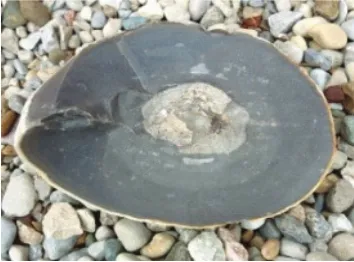
Fig. 5. – Basalt samples from France and Egypt.
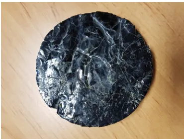
Fig. 6. – Flint stone sample.
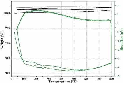
Fig. 8. – DSG and TGA curves of basalt up to 800◦C.
As shown in fig. 7, the basalt stones present very stable XRD diagrams demonstrat-ing the fact that those stones offer very stable crystal structure under heatdemonstrat-ing up to 1000◦C. Corresponding DSG and TGA characterizations have been made up to 800◦C (the highest CSP temperature today). As illustrated in fig. 8, the DSG thermal cycles demonstrate the fact that the stone presents sensible heat effect only without any king of other thermal signal which could be attributed to chemical reaction or other major transformation. The TGA curves under thermal cycling highlights a very small change in sample weight due to the departure of a slight fraction of water from the stone.
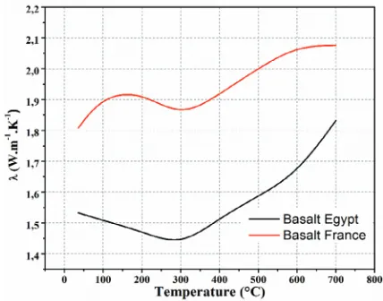
Fig. 9. – Thermal capacity of basalt stones under heating (continuous lines) and cooling (dashed lines).
that two basalts of different origins present significant differences in distributed crystals (in amount, nature sizes and shapes). Nevertheless, the range of value in thermal con-ductivity, between 1.5 to 2 W/(m K) falls within the usual range of silica-based ceramics without surprise. One other aspect could be considered as surprising: it is the fact that those thermal conductivities increase with temperature. Usually, the thermal conductiv-ity of solid materials falls with temperature. Here, the observed behavior results from not only the effect of temperature on the intrinsic thermal conductivity of the involved
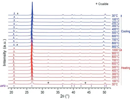
Fig. 11. – XRD diagrams in temperature of flint stones.
ceramics but also on the thermal resistances which are the interfaces between the dis-persed crystals and the main matrix. Under heating, when the thermal expansions of the crystals are higher than that of the matrix, the interfacial gaps are progressively closed and consequently the thermal resistance decrease. This results in an observed increase in thermal conductivity.
Those results associated to the fact that the observed heated samples were not broken after treatment, validate the use of basalt stones for high-temperature applications such as TES for CSP.
In the other side of stone behavior, four samples of flint (fig. 6) representative of the four main flint stone families have been experimented and characterized.
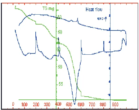
In terms of stability (see fig. 11), the XRD diagrams seems to demonstrate no change. In fact, the crystal structure does not change in nature but during the first heating the flint experiences major modifications inducing corresponding thermal signal and weight variations observed in fig. 12. At low temperature (about 100◦C), the free water de-parture induces a weight loss and a endothermic peak. From 400 to 600◦C, silanol species SiOH are transformed in Si-O bounds which participate to the stabilization of the material:
(1) SiOH + SiOH→Si-O-Si + H2O.
Fig. 12. – DSG diagram of flint stone up to 1000◦C.
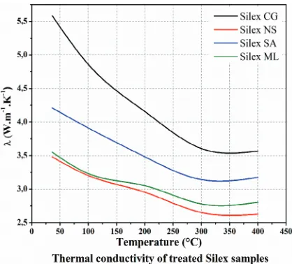
that those stone are better to be used in medium range concentrating CSP technologies (linear Fresnel and solar trough) below 400◦C while basalt stone can be used in all CSP technologies even the future high temperatures of 800–1000◦C.
In the thermal range of linear concentrating CSP technologies (below 400◦C), the thermophysical properties of the four flint samples have been characterized.
As illustrated in fig. 13, the thermal capacity under heating and cooling ranges in the usual range of silica materials with a rather conventional behavior. In terms of thermal
Fig. 14. – Thermal conductivity of flint stones up to 400◦C.
conductivity (fig. 14), the observed values (between 2.5 and 5.5 W/(m K)) are larger than those previously observed for the basalt. Those results show also a significant difference between the four samples, highlighting the effect of the composite nature of those natural product. Moreover, comparatively to the opposite behavior of the basalt, the thermal conductivities of all the experienced flint stones decrease with temperature.
Those two illustrative examples of very stable stones (basalt) and transforming stones (flint) show simultaneously the high potential of those materials for high-temperature TES applications but also their limitations and the critical need in systematic preliminary characterization before use.
In another aspect but very important for the TES application, the compatibility between those solid fillers and the HTF currently used has to be addressed properly. This has been done with hot air up to 1000◦C, with thermal oils up to 400◦C and nitrate molten salts. One major difficulty concerning this issue is the fact that those compatibility tests should be done during very long periods of times.
5.2.Recycled materials. – Considering the above limitations and bottlenecks related to TES material availability, cost and footprints, a new approach has been proposed a decade ago based on recycling inorganic industrial wastes.
This concerns asbestos-containing wastes (ACW) [8], fly ash (FA) [9, 10] and bottom ash (BA), slags from metallurgy [11] and all other mineral-like industrial wastes [12].
The first major advantage of this mineral resource is its availability. For instance, coal-fired power plants are responsible of a worldwide production of about 750 Mt/y of fly ash (micron-size spherical silica particles) released in their fumes and gathered by electrostatic filters. This first example compared to the annual CSP needs of some 20 Mt/y demonstrates the high availability of those inorganic wastes.
Fig. 15. – ACW glass obtained by fast cooling.
instance, asbestos-containing wastes are responsible for severe diseases and the only way to inert them irreversibly is to melt them to destroy their micro-fibrous structure. The problem is that this melting treatment has to be done at 1400◦C and consequently presents a high GHG and CED content. The only way to offer a positive environmental balance of the obtained inert product is to use it as high-temperature storage material. Another great advantage here is the fact that the melting step offers the possibility to control the cooling period and consequently the structure and properties of the obtained ceramic. Moreover, this cooling step can be made in a mould to produce a shaped TES module allowing an efficient heat transfer with the flowing HTF used to charge/discharge the material.
The particular case of metallurgic slags is even better: as slags are directly produced under molten state at the outlet of the metallurgic furnaces, the TES materials and modules can be directly made without additional heat treatment.
Concerning Fly Ashes, as they are in the form of micron-size spherical particles, they can be shaped in the form of TES modules by sintering, which is less costly (in terms of energy and financial costs) than melting.
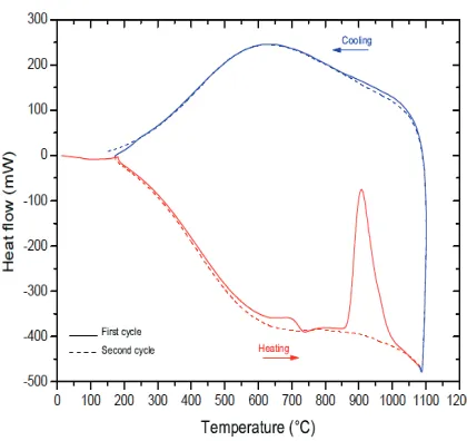
Fig. 17. – MSWI fly ash glass and ceramic DSG.
Among the possible reserve about this approach is the fact that, using industrial wastes as primary mineral resource, one could expect to get very variable properties of the obtained recycled ceramics. In fact, even if those materials contain a large amount of impurities, the four major components are always the same and they mainly impose the whole behavior and properties of the recycled ceramics.
As an example, municipal solid-waste incinerator ACW glass and ceramics have been studied. When the molten inert waste is cooled very fast, the matter has no time to form its crystal structure and we get a glass (fig. 15, an amorphous matter). If cooled at a lower rate, the material crystallizes and we get a ceramic such as in fig. 16.
Those two forms of recycled material have been characterized in terms of structure and properties. As illustrated in fig. 17 in the particular case of (MSWI) fly ash (similar results were obtained for the other wastes) under heat treatment, the DSG of the glass presents a vitrous transition peak at about 680◦C followed by a strong crystallization peak at 900◦C. The formed ceramic when cooled down to the room temperature and then submitted to a new full thermal cycle (dash lines) presents only sensible heat without any other effect. In terms of crystal structure, as illustrated in the XRD diagrams of fig. 18 the glassy material presents an amorphous flat curve, first crystals appear at about 900◦C confirming the DSG results and the other diagrams made on the ceramic under thermal cycling demonstrate a very stable crystal structure.
Those results highlight a very stable thermal behavior of those recycled ceramics up to more than 1000◦C.
Fig. 18. – MSWI FA glass and ceramic XRD underT.
Fig. 19. – Thermal capacity of ACW ceramic.
Fig. 21. – Thermal conductivity of ACW ceramic.
In terms of thermal conductivity, the two recycled ceramics present different behav-iors. As illustrated in figs. 21 and 22, ACW ceramics present thermal conductivities in the range of 1.5 W/(m K) decreasing with temperature while MSWI ceramics present an increasing behavior for a similar range of values.
Therefore, the main thermophysical properties of the recycled ceramic are in the range of the expected values for high-temperature TES applications.
Another issue specifically critical for large scale industrial TES is the ability of the
Fig. 23. – Concentrating solar facility to test the ability of the ceramic to sustain thermal shocks.
storage materials to sustain repeated thermal cycling during 20 to 30 years between two levels of temperature [13], sometimes under pressure and in contact with a HTF for which the storage material has to offer a proper chemical compatibility. Obviously, those issue are very difficult to address at lab scale and during studies of reduced periods of time.
Nevertheless, corresponding works are achieved in labs and related industries. As illustrative examples, the resistance to thermal shocks are tested in Promes-Odeillo under direct concentrated solar radiation (fig. 23) allowing severe heat treatments as in fig. 24 for which ACW ceramics were submitted to thermal cycles between 500 and 1000◦C under air with heating and cooling rates from 100◦C/min to 2500◦C/min [13].
Fig. 25. – Ultrasonic equipment for the measurement of Young modulus under temperature.
The ceramic material was able to sustain those extreme treatments without failure and consequently they will be able to sustain the much smarter usual conditions of industrial TES.
In terms of thermomechanical properties, the Young modulus and dilatometry of the recycled ceramics have been studied [13] using an innovative equipment (GEMH Limoges France). As schemed in fig. 25, an alumina guide allows to separate the electronic equipment and the sample placed at high temperature in a furnace. A transducer is used to produce ultrasonic waves and the echoes from the material lead to the Young modulus calculation. Done under cycling temperature, this gives numerous information (fig. 26) on the thermomechanical properties and behavior of the material and their possible modifications during the cycling.
Fig. 27. – XRD diagrams of ACW ceramics submitted to high-pressure high-T cycling under hot air.
This characterization can be advantageously used to assess a material, to select the proper one for a particular applications and also to study its fatigue during its industrial operation.
Another important aspect, as mentioned above, is the compatibility of the TES mate-rial with the HTF and working conditions [14,15]. This is well illustrated by the evolution of the ACW ceramics submitted to high-temperature thermal cycling under pressurized air. Under atmospheric pressure, those ceramics present no change in structure but as shown in figs. 27 and 28, under pressure the ceramic initially made of 50% Augite and
Fig. 29. – Flat plate and corrugated plates of recycled ceramic.
Wollastonite is made after 2000 h of treatment of Augite only. This demonstrates how important could be to assess the ability of a storage material to be used under realistic working conditions.
Those materials have been produced under various shapes (fig. 29) and sizes such as spheres, cylinders, plates, corrugated plates, etc. This allows to develop structured heat storage packing (fig. 30) for which the plate thickness and geometry are designed to optimize simultaneously the heat transfer coefficient with the HTF, the pressure drop and the charge/discharge of the material deep to its center. The advantage of those geometries is also due to the fact that they are self-supported (avoiding any mechanical stress on the TES envelop) and they are highly modular (allowing easy scale-up).
The LCA of this approach has been studied and compared to the current two-tank molten salt technology [16]. It highlights that even if the environmental and energy pay-backs of the waste heat treatment needed for dangerous wastes is less than 2 years, the impact of this waste treatment on the comparative LCA is favorable for the molten salt. In the case of fly ash or slags, the advantage is clearly for the recycled ceramics.
Up to date, the ACW heat treated in Europlasma/Inertam-France led to ground inert basalt-like materials for which the sole market of road base ground particles was identified. As the owner of the initial dangerous waste has to pay for the treatment itself, the price at which the granular material is sold is about 10¤/t. Compared to usual prices of high-temperature refractory ceramics ranging from 2000 to 9000¤/t, this demonstrates the potential of producing well-shaped proper recycled ceramics for TES applications.
5.3.Other approaches. – Among other developed alternative, we can mention the TES technology using high-temperature concrete of the DLR (Germany) [17]. This approach consider advantageously that concrete is a very common material, highly available, at low cost, it can be easily shaped and it presents storage capacities similar to other ceramics or rocks.
Nevertheless, usual concrete used for buildings is not supposed to be used an d cycled at high temperature. Moreover, concrete contains a high amount of water and a signifi-cant part of it should be removed properly during the first heating. This imposes a time-and energy-consuming first treatment during which the energy corresponding to the la-tent heat of evaporation has to be paid. In another field, concrete presents rather low thermal conductivity (about 1 W/(m K)) and then, an extended multitubular heat ex-changer has to be embodied into the concrete blocks to guarantee the needed heat transfer rate. Obviously, this embodied heat exchanger increases the cost of the storage and the complexity of the dismantling step of the unit. This concrete-based TES for CSP is cur-rently tested at pilot scale in Almeria (Spain) associated to nitrate phase change storage materials for the particular case of direct steam generation (DSG) future CSP plants.
6. – Conclusions and perspectives
The thermal energy storage for CSP offers new opportunities for innovations which are critically needed for their industrial growth to achieve the expected energy transition. Several emerging approaches are already under progress and will be also applied to other kinds of applications such as for ACAES (adiabatic compressed-air electricity storage) [18] or the valorization of industrial waste heat [19].
REFERENCES
[1] Py X., Azoumah Y. and Olives R., “Concentrated Solar Power: current technologies,
major innovative issues and applicability to West African Countries”, Renew. Sustain. Energy Rev.,18(2013) 306.
[2] Gil A., Medrano M., Martorell I., Lazaro A., Dolado P., Zalba B.andCabeza
L. F., “State of the art on high temperature thermal energy storage for power generation.
Part 1 - concepts, materials and modellization”,Renew. Sustain. Energy Rev.,14(2010) 31.
[3] Calvet N., Gomez J., Faik A., Roddatis V. V., Meffre A., Glatzmaier G. G.,
Doppiu S. and Py X., “Compatibility of a post-industrial ceramic with nitrate molten
salts, for use as filler materials in a thermocline storage system”, Appl. Energy, 109 (2013) 387.
[4] Burkhardt J. J., Heath G. and Turchi C. S., “Life cycle assessment of a parabolic
trough concentrating solar power plant and the impacts of key design alternatives”, Environ. Sci. Technol.,45(2011) 2457.
[5] IEA International Energy Agency, Technology Roadmap: Concentrating Solar Power (OECD/IEA) 2010,www.iea.org/roadmaps.
[6] Pihl E., Kushnir D., Sanden B. and Johnsson F., “Material constraints for
concentrating solar thermal power”,Energy,44(2012) 944.
[7] Arthur O.andKarim M. A., “An investigation into the thermophysical and rheological
properties of nanofluids for solar thermal applications”,Renew. Sustain. Energy Rev.,55 (2016) 739.
[8] Py X., Calvet N., Olives R., Meffre A., Echegut P., Bessada C., Veron E.and
Ory S., “Recycled Material for Sensible Heat Based Thermal Energy Storage to be Used
in Concentrated Solar Thermal Power Plants”,J. Sol. Energy Eng.,133(2011) 1.
[9] Kere A., Py X., Oliv`es R., Goetz V., Sadiki N. and Mercier-Allart E., “High
temperature thermal energy storage material from vitrified coal-fired power plant Fly-Ash”,Innostock 2012, 12th International Conference on Energy Storage, 16–18 May 2012, Lleida, Spain.
[10] Meffre A., Py X., Olives R., Bessada C., Veron E. and Echegut P., “High
Temperature Sensible Heat Base Thermal Energy Storage Materials Made of Vitrified MSWI Fly Ashes”,Int. J. Waste Biomass Valoriz.,6(2015) 1003.
[11] Kere A., Dejean G., Sadiki N., Olives R., Goetz V., Py X.andMercier-Allart
E., “Vitrified industrial wastes as thermal energy storage materials for high temperature
applications”, WasteEng 2012, 4th International Conference on Engineering for Waste and Biomass Valorisation, 10–13 September 2012, Porto, Portugal.
[12] Gutierrez A., Mir´o L., Gil A., Rodr´ıguez-Aseguinolaza J., Barreneche C.,
Calvet N., Py X., Fern´andez A. I., Gr´ageda M., Ushak S. and Cabeza L. F.,
“Advances in the valorization of waste and by-product materials as thermal energy storage (TES) materials”,Renew. Sustain. Energy Rev.,59(2016) 763.
[13] Meffre A., Tessier-Doyen N., Py X., Huger M.andCalvet N., “Thermomechanical
characterization of waste based TESM and assessment of their resistance to thermal cycling up to 1000◦C”,Waste Biomass Valoriz.,7(2016) 9.
[14] Motte F., Falcoz Q., Veron E.andPy X., “Compatibility tests between Solar Salt and
thermal storage ceramics from inorganic industrial wastes”,Appl. Energy,155(2015) 14.
[15] Kere A., Sadiki N., Py X. and Goetz V., “Applicability of thermal energy storage
recycled ceramics to high temperature and compressed air operating conditions”,Energy Convers. Manag.,88(2014) 113.
[16] Lalau Y., Py X., Meffre A.andOlives R., “Comparative LCA between current and
[17] Laing D., Steinmann W. D., Tamme R.andRishter C, “Solid Media thermal storage
for parabolic trough power plants”,Sol. Energy,80(2006) 1283.
[18] Jubeh N. M. and Najjar Y. S. H., “Green solution for power generation by adoption
of adiabatic CAES system”,Appl. Therm. Eng.,44(2012) 85.
[19] Miro L., Gasia J. and Cabeza L. F., “Thermal energy storage (TES) for industrial