* Corresponding author: [email protected]
Plasma edge modelling with ICRF coupling
Wei Zhang1,2,3*, David Coster1, Yuhe Feng4, Tilmann Lunt1, Diogo Aguiam5, Roberto Bilato1, Volodymyr Bobkov1, Jonathan Jacquot1, Philippe Jacquet6, Ernesto Lerche6, Jean-Marie Noterdaeme1,2, Wouter Tierens1, the ASDEX Upgrade Team1, the EUROfusion MST1 Team7
1Max-Planck-Institut für Plasmaphysik, D-85748 Garching, Germany 2Applied Physics Department, Ghent University, B-9000 Ghent, Belgium
3Institute of Plasma Physics, Chinese Academy of Sciences, 230031 Hefei, P. R. China 4Max-Planck-Institut für Plasmaphysik, D-17491 Greifswald, Germany
5Instituto de Plasmas e Fusão Nuclear, Universidade de Lisboa, 1049-001 Lisboa, Portugal 6CCFE, Culham Science Centre, Abingdon, OX14 3DB, UK
Abstract. The physics of Radio-Frequency (RF) wave heating in the Ion Cyclotron Range of Frequencies (ICRF) in the core plasmas of fusion devices are relatively well understood while those in the Scrape-Off Layer (SOL) remain still unresolved. This paper is dedicated to study the ICRF interactions with the plasma edge, mainly from the theoretical and numerical point of view, in particular with the 3D edge plasma fluid and neutral transport code EMC3-EIRENE and various wave codes. Here emphasis is given to the improvement of ICRF coupling with local gas puffing and to the ICRF induced density convection in the SOL.
1 Introduction
The coupling of Radio-Frequency power in the Ion Cyclotron Range of Frequencies (ICRF) to the plasma depends sensitively on the plasma density in front of the antennas because the launched fast wave is evanescent below the cut-off density, usually of the order of 1018 m-3
for typical frequencies and antenna spectrum in nowadays tokamak. Recent experiments on AUG [1] and JET [2, 3] indicate that by injecting the fueling gas from the main chamber instead of the divertor, the local density in front of the antennas and thus the ICRF power coupling can be greatly increased. The corresponding EMC3-EIRENE simulations [4-6] successfully reproduce these experiments and deepen our understanding on the associated physics. This paper will review these results, summarize the mechanisms and make extrapolations to ITER and DEMO.
While generating the fast wave (𝐸𝐸⊥≫ 𝐸𝐸∥, parallel
direction along 𝐵𝐵⃗ ) to heat the core plasmas, the slow wave is also excited parasitically. The parallel electric field of the slow wave, especially close to the limiters of the antennas, is expected to be the source of the nonlinearly enhanced sheath potential in front of the antennas by accelerating the more mobile electrons out of the plasma. The inhomogenous sheath potential drives E×B drifts in the Scrape-Off Layer (SOL) and modifies the plasma density locally. To understand this ICRF induced SOL density convection, two numerical methods have been developed: (a) simulations based on experimental data; (b) self-consistent simulations with
several codes including EMC3-EIRENE [7] (extended to include prescribed drifts [8] and plasma convection), RAPLICASOL [9] (ICRF fields) and SSWICH [10] (rectified sheath potentials). This paper will review these two numerical methods and the corresponding results.
2
ICRF coupling
The local density in front of the ICRF antennas can be tailored by changing the deuterium (D2) gas puff locations. While changing the gas puff locations, no clear change of the energy confinement time and no plasma degration are seen [3]. To understand the effects of localized gas sources on the SOL density, comprehensive 3D simulations with the EMC3-EIRENE code on AUG [4], JET [5] and ITER-relevant [6] scenarios have been carried out.
In our simulations, toroidal 360o grids are used and
gas source is switched from the divertor to other locations of the machine to investigate other gas puffing cases.
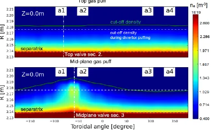
Gas puffing from different locations of the machine ultimately lead to different SOL densities in front of the antenna. Such an example in AUG H-mode plasmas is shown in Fig. 2. Compared to divertor gas puffing, top gas puffing increases the SOL density near the outer mid-plane, where the antenna are located, almost
toroidal uniformly but to a small extent, and this density increase is independent of the toroidal position of the top gas valve. Mid-plane gas puffing increases the SOL density very significantly but locally, and this density increase depends sensitively on the toroidal position of the mid-plane gas valve. The largest density increase is found in locations close to the gas valve and this increase decays in the toroidal direction. Same phenomena are observed also in JET.
Fig. 2. Toroidal cross-sections (in the outer mid-plane) of the edge electron densities simulated by EMC3-EIRENE for top and mid-plane gas puffing in AUG H-mode plasmas. The white dashed line is the cut-off density during divertor gas puffing and is used as reference; the green line is the cut-off density during top or mid-plane gas puffing; the vertical dash-dotted lines represent the toroidal positions of the gas valves. The four ICRF antenna positions are represented by a1, a2, a3 and a4. Figure reproduced with permission from [4].
The mechanisms of the local density increase with local gas puffing are summarized as follows. Gas puffing provides a local particle source. In a steady state, the ionized particles (ions+electrons) leave this ionization zone mainly via convection along the field lines. The associated convective energy flux and the power losses into the ionization processes provide an energy sink to the background plasma and thereby lower the plasma temperatures in the ionization region due to the finite classical heat conductivity, resulting in a local density rise as a consequence of the parallel pressure conservation.
The 3D plasma density obtained from the EMC3-EIRENE simulations are then used in the antenna codes such as FELICE [11] and RAPLICASOL [9] to calculate the antenna resistance 𝑅𝑅𝑐𝑐. Good agreements are
found between the calculated and measured values. For top gas puffing, the increase of 𝑅𝑅𝑐𝑐, ~25% in AUG and
~40% in JET H-mode plasmas, is almost the same for all the antennas. For mid-plane gas puffing, the largest increase of 𝑅𝑅𝑐𝑐, ~120% both in AUG [1] and JET [3]
H-mode plasmas, is found for the antenna closest to gas valve. This value decays with the distance between the antenna and valve becomes larger: the decay length is ~3.7m in AUG [1, 4] and ~3.0m in JET [3]. The difference of the decay lengths in various machines can be attributed to the peculiarity of the wall structures (for instance JET has wide poloidal limiters), different magnetic field geometries and plasma transport properties. Nevertheless, the results in AUG and JET strongly suggest that mid-plane gas valves close to the antenna is the best option to maximize the ICRF power coupling.
3 ICRF induced plasma convection
The interaction between the ICRF waves and SOL plasma is a complex nonlinear process: (1) the plasma density influences the E∥ fields; (2) the E∥ fields lead to
an inhomogenous Direct Current (DC) sheath potential, VDC; (3) the inhomogenous VDC drives E×B drifts in the
SOL and modify the plasma density. The new plasma density will change the E∥ fields, i.e. the loop comes to step (1) again.
A first simulation strategy is to use the measurements of the sheath potential of the reciprocating Retarding Field Analyzer (RFA) to estimate the E×B drifts, recently implemented in EMC3-EIRENE [8]. This makes possible to compare the impact of the E×B drifts on the density, predicted by EMC3-EIRENE, with the measurements of RFA or reflectometries. In our calculations, the averaged parallel energy < 𝑊𝑊∥(𝑡𝑡) >
measured by the RFA is equal to the Bohm energy plus the time-averaged (DC) sheath potential when assuming mono-energetic ions at sheath entrance [12], i.e.
< 𝑊𝑊∥(𝑡𝑡) >=< 𝑀𝑀𝑖𝑖𝑢𝑢𝐵𝐵𝐵𝐵ℎ𝑚𝑚2 /2 > +< 𝑒𝑒𝑉𝑉𝑠𝑠ℎ(𝑡𝑡) >
in which 𝑢𝑢𝐵𝐵𝐵𝐵ℎ𝑚𝑚 is the ion sound speed, < 𝑀𝑀𝑖𝑖𝑢𝑢𝐵𝐵𝐵𝐵ℎ𝑚𝑚2 /2 >
is the energy gained in the pre-sheath and < 𝑒𝑒𝑉𝑉𝑠𝑠ℎ(𝑡𝑡) > is
the energy gained in the sheath. Thus, the whole plasma potential (Φ𝑝𝑝𝑝𝑝) which equals to the potential drop in the
pre-sheath and sheath (Φ𝑝𝑝𝑝𝑝𝑝𝑝 and Φ𝑠𝑠ℎ) can be calculated
with Φ𝑝𝑝𝑝𝑝 = Φ𝑝𝑝𝑝𝑝𝑝𝑝+ Φ𝑠𝑠ℎ=< 𝑊𝑊∥(𝑡𝑡) >/𝑞𝑞. In addition, the
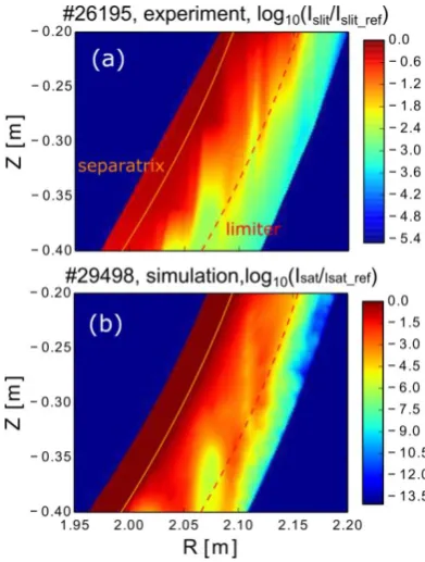
sheath potential is assumed to be nearly constant along the magnetic field lines, and its value in other toroidal positions is extrapolated by tracing magnetic field lines. Our simulation results are in good agreement with the experimental ones, Fig. 3. The results indicate that convective cells are developed where high potential blobs exist. Density depletions are found in the center of the convective cells while density accumulations are found where the plasma interacts with the wall. The plasma flows driven to the wall by the convective drifts enhance the interaction between the plasma and wall.
Fig. 3. Comparisons between experimental and simulated ion saturation current (in logarithmic scale). The ion saturation current can be expressed as Isat=qneCs, in which q is the ion charge number, ne is the electron density and Cs is the plasma sound speed. Figure reproduced with permission from [8].
The second simulation strategy is of the ab-initio type, and it requires to interface several codes in a consistency loop [13]. Before starting the iterative loop, EMC3-EIRENE simulations are done for a phase of the plasma discharge without RF, and thus without E×B drifts induced by ICRF. This is necessary to set the particle and transport coefficients of EMC3-EIRENE consistently with the experimental plasma profiles. These coefficients are assumed unaffected by ICRF heating and thus kept constant in the loop. When this setting is completed, the consistency loop for the ICRF heating phase starts by calling RAPLICASOL code to evaluate the RF E∥ fields. These fields are, then, used in
SSWICH code to calculate VDC. In the SSWICH
private scrape-off layer (σ⊥,p) and in the free scrape-off
layer (σ⊥,f) are assumed to be proportional to the parallel
(Spitzer) conductivity: σ⊥,p= Rs,pp∗ σ∥, σ⊥,f= Rs,fp∗
σ∥. Here Rs,pp= 4 × 10⁻⁶ and Rs,fp= 8 × 10⁻⁸, values
at which the sheath is near saturation and that seem to give reasonable behavior of VDC. The calculated VDC covers the antenna and these values in other toroidal positions are extrapolated starting from the two sides of the antenna based on the assumption that VDC is almost constant along the magnetic field lines. The final VDC, in turn, defines the E×B drifts for the call of EMC3-EIRENE. The iteration loop stops when the difference of a certain parameter (such as density) in one loop with that in the previous loop is lower than 5%. An example of this self-consistent simulation loop is shown in Fig.4. Three cases have been investigated: (a) 2-strap antenna with power balance between the left and right straps Pleft⁄Pright=1:1 (the most typical settings for
2-strap antenna); (b) 3-strap antenna with power balance between the central and outer straps Pcenter⁄Pouter=3:2
(optimized power balance); (c) 3-strap antenna with Pcenter⁄Pouter=1:9 (non-optimized power balance). All
the studied cases are with dipole phasing. The results (Fig. 4) indicate that the largest density convection happens in the top and bottom of the antennas. The largest sheath potential and density convection are induced by the 2-strap antenna (Case (a)) while the lowest values are induced by the 3-strap antenna with optimized power balance (Case (b)).
4 Conclusions
Through edge plasma modelling with ICRF coupling, significant progresses have been made on understanding (1) the effects of local gas puffing on edge plasma density and ICRF coupling; (2) the ICRF induced density convection.
The 3D SOL plasma density during different gas puffing are simulated with the EMC3-EIRENE code, which are then used in the antenna codes to calculate the coupling resistances. Different gas puffing cases in AUG and JET have been extensively studied and extensive comparisons between the simulations and experimental results have been made. It is shown that the gas vavles close to the antennas increase the local density and thus the ICRF power coupling most significantly. This conclusion is expected to be also true for other and future machines. Similar numerical studies for ITER and DEMO are being carried out to figure out optimized gas valve postions for the best ICRF power coupling.
The ICRF induced density convection has been studied either by EMC3-EIRENE simulations based on experimental data or by self-consistent simulations with several codes (EMC3-EIRENE + RAPLICASOL + SSWICH). Our simulation results are in qualitative agreement with the measurements. It is indicated that convective cells are often developed in the top and bottom of the antennas. The convective drifts change the density in front of the antenna locally, influence the
Fig. 4. Results of the self-consistent loop, including 𝐸𝐸∥ calculated with the RAPLICASOLcode, 𝑉𝑉𝐷𝐷𝐷𝐷 calculated with the SSWICH
ICRF power coupling and enhance the plasma-wall interactions. Among the studied cases, the 3-strap antenna with optimized feeding configurations leads to the lowest rectified sheath potential and density convection. The developed numerical methods can be further used to predict and optimize the experiments. This work has been carried out within the framework of the EUROfusion Consortium and has received funding from the Euratom research and training programme 2014-2018 under grant agreement No 633053. The views and opinions expressed herein do not necessarily reflect those of the European Commission.
References
[1] Bobkov V. et al 2015 AIP Conference Proceedings 1689 030004
[2] Lerche E. et al 2015 Journal of Nuclear Materials 463 634-9
[3] Jacquet P. et al 2016 Nuclear Fusion 56 046001 [4] Zhang W. et al 2016 Nuclear Fusion 56 036007 [5] Zhang W. et al 2017 Nuclear Fusion 57 056042 [6] Zhang W. et al 2017 Plasma Phys. Control. Fusion 59 075004
[7] Feng Y. et al 2004 Contributions to Plasma Physics 44 57-69
[8] Zhang W. et al 2016 Plasma Phys. Control. Fusion 58 095005
[9] Jacquot J. et al 2015 AIP Conference Proceedings 1689 050008
[10] Jacquot J. et al 2014 Physics of Plasmas 21 061509 [11] Brambilla M. 1989 Plasma Physics and Controlled Fusion 31 723-57
[12] Soucek J. et al 2005 Journal of Geophysical Research-Space Physics 110 A08102
[13] Zhang W. et al 2017 Nuclear Fusion 57 116048
![Fig. 4. Results of the self-consistent loop, including reproduced with permission from [12].](https://thumb-us.123doks.com/thumbv2/123dok_us/8129335.1354723/4.595.50.544.69.374/raplicasolcode-calculated-calculated.webp)
