ISSN (Print) : 2320 – 3765 ISSN (Online): 2278 – 8875
I
nternational
J
ournal of
A
dvanced
R
esearch in
E
lectrical,
E
lectronics and
I
nstrumentation
E
ngineering
(An ISO 3297: 2007 Certified Organization)
Vol. 5, Issue 5, May 2016
A Coordinated Voltage Control using OLTC,
Voltage Regulator and DG for a Distribution
Feeder
S.Bhasker1, Anisha.K2, P.Ganesh Venkata Siva Teja3
PG Student, Department of EEE, Sri Chandrasekarendra Saraswathi Viswa Maha Vidyalaya UNIVERSITY,
Kanchipuram, Tamil Nadu, India1, 3
Assistant Professor, Department of EEE, Sri Chandrasekarendra Saraswathi Viswa Maha Vidyalaya UNIVERSITY,
Kanchipuram, Tamil Nadu, India2
ABSTRACT: The distributed generation (DG) connected into the distribution networks have become increasingly popular at the present. Also the falling price of the synchronous generator has the capability to give DG a active participation in the voltage regulation process along with other devices which are available in the system. The voltage control issue gives rise to be a challenging problem for the distribution engineers since existing control coordination schemes would required to be reconsidered to take the DG operation. In this paper,
We propose a control coordination technique, which is utilizing DG as a voltage regulator and, at the same time, minimize interaction with other active devices, such as an on-load tap changing transformer(OLTC) and also a voltage regulator.
KEYWORDS: power quality Distributed generation, STATCOM, voltage regulation
I. INTRODUCTION
On-load tap-changers (OLTCs) plays an important role in regulating power transformers used in electrical energy networks and industrial applications. The OLTC changes the ratio of a transformer by adding turns from either the primary or the secondary winding. The transformers are therefore equipped with a regulating or tap winding which is connected to the OLTC. Simple changing of taps during an energized condition is not allowable due to momentary loss of system load during the switching operation.
Apart from tap selection, the vital task of an OLTC is the break function or current (load) transferring action. The required switching capacity for a specific contact in an OLTC is based on the relevant step voltage and current but is also determined by the design and circuit of the OLTC[7]. The switching capacity is primarily a factor which helps for contact design, contact speed and arc-quenching agent.
Long-term uninterrupted availability of the regulating transformer, –> extension of the maintenance intervals
–> reduction in maintenance work I Low failure rate
I Reduction in operating costs The main requirements are
ISSN (Print) : 2320 – 3765 ISSN (Online): 2278 – 8875
I
nternational
J
ournal of
A
dvanced
R
esearch in
E
lectrical,
E
lectronics and
I
nstrumentation
E
ngineering
(An ISO 3297: 2007 Certified Organization)
Vol. 5, Issue 5, May 2016
Fig .1. co-ordinated control system
Power losses can be an issue while control coordination is Performed; it can be improved for an improved voltage profile. Moreover, voltage limits are a matter of regulatory issue, and the system is designed such that they are met. Therefore, power losses are addressed in this paper. The voltage control coordination is often necessary in distribution networks and has been a subject of interest in many research papers. Ma et al. in [5] have used the hierarchical genetic algorithm to optimize the response of voltage controllers according to the number of control actions. In [6], an integrated voltage control called coordinated secondary voltage control has been proposed for controlling the OLTC to ensure that voltage and loading constraints are satisfied during normal and emergency conditions. Another voltage regulation method in power distribution systems containing DG units has been developed in [7] through optimizing the sending end voltage using the least squares method. Baldick and Wu in [8] have coordinated the operations of switched capacitors and OLTC in a radial distribution system the problem as a constrained discrete quadratic optimization. In a method for coordinating the operation of DG and a step voltage regulator for improved distribution system voltage regulation has been presented. In a coordinated control approach is proposed for response coordination of DG and OLTC.In this paper, the strategy proposed is extended, and a control strategy for controlling the operation of the OLTC, the voltage regulator, and DG has been developed. This coordination method aims to maintain the supply voltage at an acceptable level with a combination of regulating devices, while minimizing or completely eliminating the number of counteracting operations among them.
The key idea of these coordination methods is selectivity or priority. In other words, only the correct device (or devices) should respond in a correct order to any given case of voltage fluctuation. An approach for determining the priority of each device in the system is proposed based on a zone discrimination concept. Furthermore, the operating principles of the line drop compensation (LDC) are reconsidered to provide a voltage prediction function for the OLTC, the voltage regulator, and DG. The DG systems considered in this work are schedulable devices (such as diesel, gas, biomass, and mini hydro) primarily for voltage control. The proposed approach has been simulated on a distribution feeder to examine its performance through network simulations.
However, for a better voltage control scheme, particularly when more than one voltage regulating devices are employed, a controller with a more complicated arrangement needs to be developed. The two controllers have several common functions as follows.
• LDC to monitor the voltage magnitude at target bus.
ISSN (Print) : 2320 – 3765 ISSN (Online): 2278 – 8875
I
nternational
J
ournal of
A
dvanced
R
esearch in
E
lectrical,
E
lectronics and
I
nstrumentation
E
ngineering
(An ISO 3297: 2007 Certified Organization)
Vol. 5, Issue 5, May 2016
Fig.2. components of OLTC and DG controllers
• The current status is then compared with the previous status.
• If the controller status is consistent over a period of time (called time delay), the control action will take place. The time measurement is carried out with a counter. The only difference between the OLTC controller and the DG controller is the mechanism to regulate voltage. With the OLTC, the voltage is adjusted by changing the tap position through a motor drive and a tap changer. DG, on the other hand, is altering the voltage by varying its output, using a proportional Controller.
It is assumed that the DG action is delayed by a certain amount of time. In other words, the output of DG is changing step by step toward the desired value. This is made not only to comply with the actual practice but also to give time for the voltage to be automatically recovered or for the OLTC to have a chance to be activated. Such a solution is considered to be more economical. It should be noticed that the controller of the voltage regulator, if present in the system, will have the same configuration as the controller of the OLTC.
A. Design of Controller for OLTC
Block 1: In practice, regulating devices are usually equipped with LDC facility that predicts the voltage at the remote load centre. The LDC works based on a relatively simple principle. Voltage at the load center is predicted by estimating the voltage drop and then subtracting it from the local voltage measurement at the regulating point, given as
whereV LDC pr , Vf, and Vdare the LDC predicted voltage, local voltage, and estimated voltage drop, respectively. However, the most complicated task in designing the LDC is the tuning process. Proper tuning is required in order to obtain reasonable accuracy of the prediction. A common tuning process is used in the network where load is assumed to be lumped at the remote end. Thus, voltage drop can be calculated by multiplying the equivalent line impedance (R +
jX) by the local current as
Where Ifis the local current measured at the regulating point. An advantage of this way of tuning is that only limited knowledge of the system is needed. However, since the current flow is assumed to be constant throughout the feeder, the voltage drop estimated by this method is often higher than the actual value.
ISSN (Print) : 2320 – 3765 ISSN (Online): 2278 – 8875
I
nternational
J
ournal of
A
dvanced
R
esearch in
E
lectrical,
E
lectronics and
I
nstrumentation
E
ngineering
(An ISO 3297: 2007 Certified Organization)
Vol. 5, Issue 5, May 2016
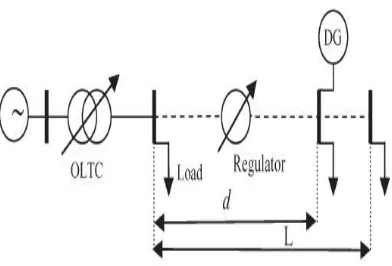
Where the current flow is expressed as a function of distance x from the substation; f and L are the distance from the substation to the regulating point and the length of the feeder, respectively; and If and Ir are the locally measured current at f and the current drawn by the remote load at r, respectively. Note that Irat any location can be calculated by dividing If by the total number of load points between x = f and x = L. The voltage drop can thus be estimated as
Where z is the line impedance per unit length. This will be used to predict the voltage at the target bus, i.e., VC. The target bus is also the last bus in the control zone of the OLTC, which is bus n. VC is compared with the reference voltage to determine if tap ratio adjustment is required. According to (9), VC can be calculated as Block 3: In block 3, the current status of the voltage error, i.e., Si, is compared with the previous status, i.e., Si−1.
Block 4: The counter is employed to determine the time duration of the voltage error exceeding the dead band. Thus, it will introduce a time delay before a tap movement. This is to avoid unnecessary tap operations to transient voltage variations and properly coordinate control actions between regulating equipment. Output C of the counter is determined
as where Δtis the time step.
The counter starts counting the time as soon as the voltage error moves outside the dead band. It will be reset if the voltage error fluctuates below and above the dead band, if the voltage error changes sign, or if the voltage error is within the dead band.
Block 5: The output of the counter C is compared with time delay TD for the tap change to determine the desired tap change, i.e., u. The desired tap change is zero if C is 0 or less than TD. It will be equal to +1 (or −1) if C is equal to or greater than TD, and Si is currently +1 (or −1). It should be noted that TD is
III. POWER QUALITY
Power quality is defined as the interaction caused by electrical power with electrical equipment. If electrical equipment operates reliably without being damaged , we would say that the electrical power is of good quality.or else if the electrical equipment is unreliable, or is damaged during normal usage, we could suspect that the quality of power is poor. There are two approaches to the mitigation of power quality problems.
Fig.3. Quality of Supply Categories
ISSN (Print) : 2320 – 3765 ISSN (Online): 2278 – 8875
I
nternational
J
ournal of
A
dvanced
R
esearch in
E
lectrical,
E
lectronics and
I
nstrumentation
E
ngineering
(An ISO 3297: 2007 Certified Organization)
Vol. 5, Issue 5, May 2016
starting of a large induction motor. But the faults in the system are the most frequent cause of voltage sags. These voltage sags leads to the majority of Equipment trips. The characteristic of sag is mainly defined by the magnitude of sag and its phase-angle.
PQ related issues are of most distress because of the extensive use of electronic equipment. In arrears to this, various Power quality issues arises like voltage sag or dip, voltage swells, harmonic distortion, voltage fluctuation, noise, voltage imbalance have altered our power system. The presence of voltage disturbances at the point of common coupling (PCC) results in improper work of sensitive industrial instrumentality, that turn out The FACTS devices are the answer to shield sensitive loads against the most significant voltage disturbances, imbalance and sags, voltage harmonics .
DISTRIBUTION STATIC COMPENSATOR (D-STATCOM)
A Distribution Static Compensator(D-STATCOM) main parts in Figure, consists of a two-level (VSC)Voltage Source Converter , a DC storage device, a coupling transformer. The Voltage source converts the DC voltage across the storage device into a three-phase alternate current and output voltages. These voltages are in coupled and phase with the ac system through the reactance of the coupling transformer. Needed adjustment of the phase and magnitude of the D-STATCOM output voltages allows effective control of reactive and active power exchanges between the Distribution Static Compensator and the ac system. Such configuration allows the device to take in or generate controllable reactive and active power. The VSC connected in shunt with the ac system provides a improper topology which can be used for up to 3 quite distinct purposes:
1.Voltage regulation and compensation of reactive power; 2. Elimination of current harmonics.
3. Correction of power factor; and
Here, such device is employed to provide uninterrupted voltage regulation using an indirectly controlled converter.
Fig.4.Configuration of a D-STATCOM
IV. SIMULATION RESULT
In this paper a co-ordinated control scheme was adopted by using OLTC which regulates the primary side voltage , Dg set which is also used to regulate the voltage ane addionally a voltage regulator, Static compensator is used to regulate the voltage of the distribution feeder. The simulation results shows the compensated voltage at 0.6 secs
ISSN (Print) : 2320 – 3765 ISSN (Online): 2278 – 8875
I
nternational
J
ournal of
A
dvanced
R
esearch in
E
lectrical,
E
lectronics and
I
nstrumentation
E
ngineering
(An ISO 3297: 2007 Certified Organization)
Vol. 5, Issue 5, May 2016
Fig.7. Wind voltage Fig.8.Wind current
V. CONCLUSION
In this paper, an algorithm for the coordination of voltage control actions of different regulating devices and statcom for regulating voltages has been developed. The coordination method has been developed based on the combination of several concepts, including the DC, control zone, setting of reference voltage, dead band, and time delay. Selection of these settings has been discussed in detailed in this paper, which makes it easier for the distribution control engineers to design a coordinated control system for distribution networks with multiple regulating devices including DG. The proposed coordination method offers a reasonable recovery time for the system voltage and, at the same time, minimizes the operating cost of regulating devices with minimizing the number of operation. Simulations have been carried out with several different setups of the voltage control devices, to test the proposed technique. The results have proven that the proposed algorithm is flexible and easy to implement in a distribution system with minimum effort to coordinate the control actions of different regulators and DG to control the feeder voltage. The novelty of this approach is that it has formulated the problem to design the voltage control coordination scheme without the support of a communication system. Selection of hysteresis levels and zones of control have been used to ensure stable coordination.
REFERENCES
[1]. STATCOM Model against SVC Control Model Performance Analyses Technique by Mat lab Tariq Masood1, R.K. Aggarwal1, S.A. Qurush, R.A.J Khan
[2]. STATCOM Operation Under Transient Disturbances for Wind Power ApplicationsIon Etxeberria-Otadui(1), Unai iscarret(1), Izaskun Zamakona(2), Beatriz Arenal Redondo(3), Javier Ibiricu(4)
[3]. A Voltage-Controlled D STATCOM for Power-Quality Improvement Chandan Kumar, Student Member, IEEE , and Mahesh K. Mishra, [4]. Localized Reactive Power Markets Using the Conceptof Voltage Control AreasJin Zhong, Emilia Nobile , Anjan Bose , and Kankar Bhattacharya
[5]. A Coordinated Voltage Control Approach for Coordination of LTC, Voltage Regulator, and DG to Regulate Voltage in a Distribution Feeder Kashem M. Muttaqi,Senior Member, IEEE , An D. T. Le, Michael Negnevitsky, Senior Member, IEEE ,and Gerard Ledwich, Senior Member, IEEE [ 6 ] . O n - L o a d T a p - C h a n g e r s f o r P o w e r T r a n s f o r m e r s A T e c h n i c a l D i g e s t,M R P U B L I C A T I O N
[7]. Electric Power Transformer Engineering, Third Editionedited by James H. Harlow