Analysis and Simulation of a Simplified 13
Level Multilevel Inverter Using Genetic
Algorithm Suitable for PV Systems
Madhusudhana J1, Sunilkumar2, P S Puttaswamy3,
Assistant Professor, Dept. of Electrical Engg, UVCE, Bengaluru, Karnataka, India1
PG Student, Dept. of Electrical Engg, UVCE, Bengaluru, Karnataka, India2
Professor, Dept. of Electrical and Electronics, PESCE, Mandya, Karnataka, India3
ABSTRACT: Inverters are used to convert the DC output of PV cells into AC. In PV power conversions, Cascaded H bridge multi-level inverters are finding more applications than other types because of its simplicity. On the other hand they suffer from increased number of power devices, complexity and losses with the increase in number of output levels. In this paper a new asymmetrical H-bridge multilevel inverter topology is proposed which uses less number of power devices for producing 13 levels in the output voltage waveform. In order to improve the quality of the output waveform and to minimize the total harmonic distortion, few lower order harmonics present in the output voltage has to be removed. Several methods are proposed which deals with the elimination of the selected harmonics. In these paper genetic algorithm techniques is proposed for solving the SHE equation. The circuit considered is simulated using equal switching angle technique and genetic algorithm optimization method in MATLAB/Simulink software. The results obtained from above two techniques are compared and tabulated in the result section.
KEYWORDS: multilevel inverter, THD, Genetic algorithm, selective harmonic elimination, MATLAB/Simulink.
I. INTRODUCTION
In recent years, the demand for medium voltage and high power application is increasing continuously, so for meeting this demand people are moving towards nonconventional energy sources mainly solar energy because it is more abundantly available in nature. This solar energy is converted into electrical energy by using photovoltaic cells, since the output of PV cell is DC in nature which is then converted into AC by means of inverter circuits. Due to the advantages of multilevel inverters like lower switching losses ,higher efficiency and more electromagnetic compatibility they have attracted a great deal of attention in medium voltage and high power applications when compared to the conventional two level inverters.
Many inverter topologies have been proposed among them most known types are diode clamped, flying capacitor and cascaded H-bridge structures[1][2][3][4]. In diode clamped inverter the number of clamping diodes required in each phase is given by (n-1) (n-2) where n is number of levels in the output voltage. This type of structures becomes impractical to implement when we go for higher levels in the output voltage because of increase in number of diodes [1]. In flying capacitor, number of clamping capacitors required in each phase is given by (n-1)*(n-2)/2 in addition to the (n-1) main DC bus capacitors. The voltage balancing across the clamping capacitors becomes major problem when the number of levels increased [2]. To overcome the disadvantages of the above two topologies cascaded H-bridge multilevel inverter has been developed, which is series connection of single phase inverter with separate dc sources. This has become an advantage in case of PV systems, because solar cells can be assembled as a number of separate DC sources. The relation between the number of levels and number of H- bridges in cascaded MLI is given by m=2n+1
value of DC input voltage are same for all the H-bridges where as in asymmetrical type the values of DC input voltages are different. Because of different values of DC sources, output levels are different in asymmetrical structures.
In this paper a new asymmetrical multilevel inverter topology have been proposed which is able to give higher number of levels in the output waveform with reduced number of power devices [5]. Hence the switching losses are reduced as a result the efficiency of the inverter increases. There are many PWM techniques have been proposed for obtaining desired output staircase waveform from the separate DC input voltage sources and they are sinusoidal pulse width modulation [6], space vector modulation [7], selective harmonic elimination [8] and optimal minimization of total harmonic distortion [9]. It is possible to eliminate the selective harmonics in order to improve the quality of the waveform and to minimize the THD by selective harmonic elimination PWM technique. But the main problem associated with this technique is it requires the mathematical solution of nonlinear transcendental equations and as the number of levels increase, the difficulty in solving these equation will also increase. To overcome these drawbacks in this paper we are going for Genetic algorithm technique [10] [11]. The optimal switching angles are calculated by using Genetic algorithm in order to eliminate certain lower order harmonics and also to minimize the total harmonic distortion. The obtained optimal switching angles are used in simulated circuit and obtained results are compared and tabulated in the result section.
II. PROPOSED MULTILEVEL INVERTER DISCRIPTION
In this paper authors have proposed a 13 level inverter, which is able to give an output voltage waveform close to a sinusoidal signal with acceptable THD. For generating a 13 level output waveform, symmetrical type uses 6 H-bridges resulting in 24 switches. The proposed topology requires only 3 H-Bridges resulting in 12 switches. This makes reduction in switches by 50%. Thus the switching complexity is reduced and the space and volume occupied by three extra H-bridge inverter stages are also reduced.
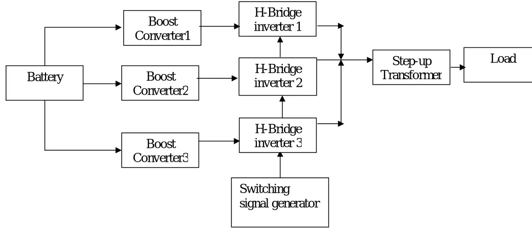
Fig 1.1 Block diagram of the proposed circuit
The block diagram of the proposed circuit is as shown above in fig 1.1. It makes use of a battery which can be considered as an equivalent to a PV module. As the output of the PV module will be at low level boost converters are used to boost the voltage levels as required by the inverter circuits. Here three different boost circuits are used which will be acting like three different DC source’s for the asymmetrical H-bridge inverter considered. The output of the inverter is fed through a transformer of suitable turn’s ratio. The transformer can be designed to operate as a filter to make the output signal more close to a sine wave. It also serves as an isolation between the inverter and the load terminals. The inverter switches are operated using suitable switching circuit. Here the switching signals can be
Boost
Converter1
Boost
Converter2
Boost
Converter3
Battery
H-Bridge
generated by PWM technique as per the switching sequence. Switching angles are optimized by using soft switching methods like Genetic algorithm, fuzzy logic etc.
Fig 1.2 shows the proposed asymmetrical inverter circuit. This circuit uses three unequal DC sources which are in the ratio 1:2:3 (V1=Vdc, V2=2Vdc and V3=3Vdc). In our circuit we have considered Vdc as 27V hence V1= 27V, V2=54V and V3=81V which are obtained by boosting up the 12V battery (equivalent of a PV module) by using boost converter. This combination of three DC sources is able to provide an output voltage of 110V (RMS) across the load terminals. A 1:2 transformer is employed at the output of the inverter in order to get 220V (RMS) at the output which is suitable for standalone photovoltaic applications.
Fig 1.2 A new 13 level asymmetrical multilevel inverter topology
Voltage S1 S2 S3 S4 S5 S6 S7 S8 S9 S10 S11 S12
6 Vdc 0 0 1 1 0 0 1 1 0 0 1 1
5 Vdc 0 0 1 0 0 0 1 1 0 0 1 1
4Vdc 0 0 1 1 0 0 1 0 0 0 1 1
3Vdc 0 0 1 0 0 0 1 0 0 0 1 1
2Vdc 0 0 1 0 0 0 1 1 0 0 1 0
Vdc 0 0 1 1 0 0 1 0 0 0 1 0
0 0 0 1 0 0 0 1 0 0 0 1 0
-1Vdc 1 1 0 0 0 1 0 0 0 1 0 0
-2Vdc 0 1 0 0 1 1 0 0 0 1 0 0
-3Vdc 0 1 0 0 0 1 0 0 1 1 0 0
-4Vdc 1 1 0 0 0 1 0 0 1 1 0 0
-5Vdc 0 1 0 0 1 1 0 0 1 1 0 0
-6Vdc 1 1 0 0 1 1 0 0 1 1 0 0
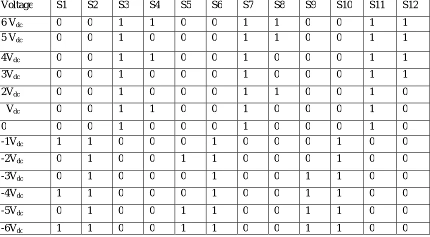
Table 1. 13 level multilevel inverter with three unequal voltage sources switching states
The 13 levels in the output waveform are obtained by following a proper switching sequence as given in the table 1.1. The different levels obtained are listed as below. Vdc=27V, 2Vdc=54V, 3Vdc=81V, 4Vdc=108V, 5Vdc=135V, 6Vdc=162V, 0V, -Vdc=27V, -2Vdc=54V, -3Vdc=81V, -4Vdc=108v, -5Vdc=135V, -6Vdc=162V.
2.1 FILTER DESIGN
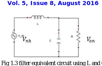
Fig 1.3 filter equivalent circuit using L and C
The condition for the nth harmonic ripple to pass through the capacitor is given by.
R >>
This condition is generally satisfied by the relation
R = …….. (a)
Where n is nth harmonics and is the fundamental harmonics in rad/sec
The rms value of the nth harmonic component appearing on the output can be found by using the voltage divider rule and is expressed as
= (
( ) ) ………(b)
For a specified value of and the value of C obtained from the equation (a) the value L can be computed. For simplifying the computation only dominating harmonics are considered. In this case we found that the 3rd harmonic is dominating and is to minimized and the DC value,
= ………. (c)
Now the ripple factor is given by ratio of to the in this case it is taken as 10% Ripple factor (Rf) = ……….………. (d)
By using above equations we found the values of C = 110 uF and L = 10 mH and these values are used in the simulation.
= ……… (e)
Where,
N= Number of turns L= Inductance P= Permeance
Here in this paper, while simulating the circuit in place of inductor we are using transformer. By using transformer three objectives would be fulfilled. As transformer will act like filter, it will also provide isolation and it will boost up the voltage. In simulation our all objectives has been fulfilled by using transformer in the circuit. As the operating frequency used in the circuit is 50Hz, which makes the hardware size bigger and bulky.
III. SELECTIVE HARMONIC ELIMINATION PROBLEM IN CASCADED MULTILEVEL INVERTER
The Fourier series expansion of the output voltage waveform shown in fig 2 is expressed as
( ) = ( sin( ) + cos( ))………. (1)
Since =0, that is the even harmonics are zero due to the quarter wave symmetry of the output voltage, hence only odd harmonics will be present in the waveform. The amplitude of the nth harmonic is calculated from the Fourier series factor shown in equation (2) and only first quadrant switching angles are calculated due to the symmetry of the waveform.
= (4 /n ) cos(n )……….. (2)
Where m is the variable which represents the switching angles through of the first quadrant, in this case from to
And
In selective harmonic elimination method, the fundamental harmonic amplitude ( ) is assigned to some desired values of modulating index and amplitude of the harmonics which are to be eliminated are made equal to zero. In this an attempt is made to eliminate 5th and 7th harmonics.
= (4 / ) cos( )= M………. (4)
= (4 /5 ) cos(5 ) = 0……….. (5)
= (4 /n ) cos(n ) = 0 ………. (6) Where,
M is the modulation index.
By solving the above equations obtain the switching angles. Since the above equations are nonlinear transcendental in nature, solving the simultaneous equations becomes difficult. There are several methods has been suggested for solving the SHE-PWM nonlinear equations but in this paper only genetic algorithm optimization technique is discussed.
A. GENETIC ALGORITHM (GA)
The basic idea of the evolutionary algorithms is to convert the SHE problem into the optimization problem. In this paper we are using genetic algorithm optimization technique which can be used for solving both the constrained and unconstrained optimization problems. GA can be applied to solve the problem of selective harmonic elimination of any levels of the inverter because it is a simple algorithm and easy to implement also it does not require any complex derivation or mathematical modeling.
The process of any Genetic Algorithm optimization technique can be divided into the fallowing steps 1) Initialization of the population, 2) Evaluation of fitness function, 3) Selection, and 4) Apply genetic operators. Figure (4) presents a general flow chart for genetic algorithm [12].
STEP_1: Initialization population: it is the first step of the GA which generates set of solution randomly. Each set of solution refers to switching angles of the inverter and they are called as chromosomes. The number of chromosomes generated is depend on the population size in this problem it is taken as 20 and each chromosome has 6 gens means 6 switching angles ( to ) required for producing the 13 level output waveform.
STEP_2: Evaluation of Fitness Function: A fitness function is to be used as a measure in order to test the goodness of the Generated solution. In this paper the THD % is taken as the fitness function and it is minimized and it is given below.
%THD= [ ( ) ] ……….. (6)
Where, is the amplitude of the fundamental component and is the amplitude of the nth harmonics. In this paper 5th and 7th harmonics are minimized and fitness function is considered according to the need. This fitness function is evaluated for each iteration and it gives the optimal switching angles which gives less THD. In this paper we are 100 iterations.
STEP_3: Selection stage: In this stage for producing the offspring chromosomes parent chromosomes are selected based on the selection rules. In this the fittest individual are likely to survive and the less fit are eliminated.
Fig 1.4. Flow chart of the genetic algorithm
IV. ANALYSIS AND SIMULATION OF THE PROPOSED CIRCUIT
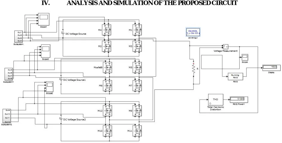
Fig 1.5 matlab/Simulink model of the proposed circuit
rms. The switching sequence and pulse width duration of the switches present in the H Bridge has been designed to get an output signal at a frequency of 50Hz. The proposed circuit is simulated using Genetic algorithm optimization technique. The instants at which the switches turn on and their conduction period are tabulated in the table 1,1. The analysis and simulation has been made with and without filter and the obtained results and waveforms are presented below.
A. SIMULATION RESULTS OF PROPOSED CIRCUIT WITHOUT FILTER
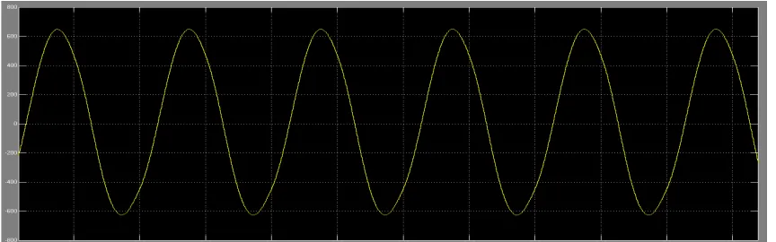
Fig 1.6 13 level output waveform obtained from the genetic algorithm without filter
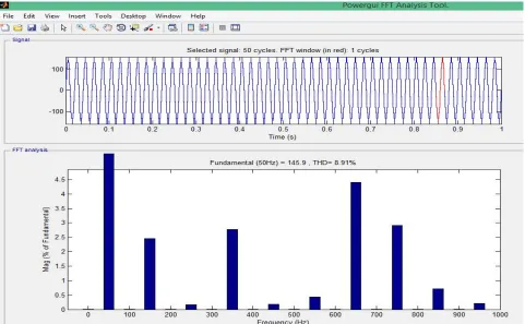
Fig 1.8 13 level output waveform harmonic analysis obtained from the genetic algorithm without filter
B.SIMULATION RESULTS OF PROPOSED CIRCUIT WITH FILTER
Fig 1.9 simulated circuit of proposed circuit with filter
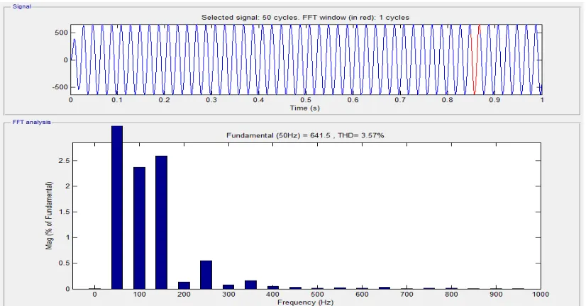
Fig 2.1 13 level output waveform Harmonic analysis obtained from the genetic algorithm with filter
Fig 2.2 13 level output waveform harmonic analysis obtained from the genetic algorithm with filter
13 level Without filter with filter
THD% THD%
Total 8.91 3.57
3rd 2.44 2.3
5th 0.14 0.55
7th 2.77 0.16
V. CONCLUSION
With genetic algorithm optimization 13 level inverter circuit is simulates with SHE considered. LC filter is being used in order to improve the quality of the output voltage waveform and making it to more sinusoidal. LC filter is designed so that the lower order harmonics percentage in output gets decreased. As the severity of lower order harmonics are very large, so by successfully removing those, the obtained output voltage can be used for various critical applications. From the above given tabular it can be observed that the reduction in overall THD is very much significant and the corresponding 5th and 7th harmonics has got decreased. With reference to the obtained results it is concluded that GA is more effective in removing the lower order harmonics.
REFERENCES
1. Jose rodriguez, Jhi-sheng lai, Fang Zheng Peng “Multilevel inverters: A survey of topologies, controls, and applicaitons”.IEEE taransactionon
industrial electronics volume 49 no-4 August 2002.
2. T. A. Meynard and H. Foch, "Multi-level choppers for high voltage applications," Eur. Power Electron. Drives J., vol. 2, no. I, p. 41, Mar.l 992.
3. A. Nabae, 1. Takahashi, and H. Akagi, "A new neutralpoint clamped PWM inverter," IEEE Trans. Ind. Applicat., vol. IA-J7, pp. 518-523,
Sept./Oct. 1981.
4. J. S. Lai and F. Z. Peng, "Multilevel converters-A new breed of power converters," IEEE Trans. Ind. Applicat., vol. 32, pp. 509-517, May/June.
1996.
5. Madhusudhana J, P S Puttaswamy, Harshit Agrawal “A comparative analysis of different multilevel inverters” International Journal of
Advanced Research in Electrical, Electronics and Instrumentation Engineering(IJAREEIE) Vol. 5, Issue 7, July 2016 ISSN (Print): 2320 – 3765 ISSN (Online): 2278 – 8875.
6. Feel-Soon Kang, Sung-Jun Park “Multilevel PWM Inverters Suitable For The Use Of Stand Alone Photovoltaic Power Systems” IEEE
Transaction On Energy Conservation, Vol _20, No-4, December 2005.
7. Massoud A.M., Finney S.J., Cruden A., Williams B.W.: “Mapped phase-shifted space vector modulation for multilevel voltage source
inverters‟, IET Electr. Power Appl., 2007, 1, (4), pp. 622–636
8. Goldberg D.E. (1989). “Genetic Algorithm in Search, Optimization and Machine Learning”, MA: Addison Wesley
9. Madhusudhana J, P S Puttaswamy, Sunilkumar “genetic algorithm based 15 level modified multilevel inverter for stand alone applications”in
the international journal of modern trends in Engineering and Research published in IJMTER (e-ISSN: 2349-9745, Volume 3, Issue 6, June 2016).
10. L. Chambers.( 1995) “Practical handbook of genetic algorithms”( Boca Raton, CRC Press.
11. Darshan Kumar, Dr. Swapnajit Pattnaik, Mrs. Varsha Singh, “Genetic Algorithm Based Approach for Optimization of Conducting Angles in
Cascaded Multilevel Inverter”,International Journal of Engineering Research and Applications, Vol. 2, Issue 3, May-Jun 2012, pp.2389-2395
12. Kalyanmoy Deb. ' Multi-Objective Optimization Using Evolutionary Algorithms ' First edition, (Wiley, New York,2010) [15] R.N. Ray D.