DOI : https://doi.org/10.32628/CSEIT195362
Intelligent Deployable Mini Rover from the Mars Rover for Deep
Narrow Scientific Investigation
Muhammed Sharukh1, Badsha Karim2, Sajin NV3, Jameson Thomas4
1,2Department of Electrical Engineering, KMP College of Engineering, Ernakulam, Kerala, India
3Department of Computer Science Engineering, KMP College of Engineering, Ernakulam, Kerala, India
4Department of Electrical Engineering, Caarmel College of Engineering, Pathanamthitta, Kerala, India
ABSTRACT
The paper describes various issues faced by mini rover deployed from main rover in an alien environment and the ways to solve them. The rover features a rocker bogie mechanism with differential drive, collision free distance sensing, wireless XBee control and camera Vision. The rover features a flexible segmented body with a
multipurpose arm, corresponding multi wheel mechanism and Kinect module integration for advanced image
processing. The system control, for both the Rover as well the robotic arm integrated with it, is done using feasible yet extremely efficient microcontrollers and microprocessors such as Arduino, Raspberry pi etc. Inspired from nature, a reflex mechanism has also been integrated into the rover design to minimize damage, by automated safety reflexes. The six wheeled rocker bogie mechanism ensures that it can traverse over a considerable height greater than the chassis height which could be as much as twice the diameter of the wheels. The rocker bogie mechanism provides traction due to its body weight. The rover finds applications in the exploration of other planets and harsh environments. Such an effort may even prove to be instrumental in detection and study of biological activity in worlds other than ours.
Keywords: Arduino, Camera Vision, Image Processing, Kinect, Raspberry Pi, Rocker Bogie, Rover
I. INTRODUCTION
The human body, with its limited form and senses, can only explore a small portion of the physical world. However this limitation is a handicap to the infinite potential of the human intellect, which strives to discover the ends of the world. Technology has more or less removed this limitation by allowing man to explore to the deepest seas and the farthest galaxies.[1-3] This paper deals with one such technological advancement. Technology has come a long way since the first rovers were designed for deep sea explorations. Today most of the missions to deep sea vents, distant galaxies and neighboring planets are
handles using multifunctional Rover bots. The Mars Rover is a vehicle that has been designed to traverse the rugged terrains of Mars and collect samples of
various items on Mar’s surface. Scientists over the
with the ground always. This advantage is key to creating a stable all terrain system. Consequently, the traction of the rocker bogie provides is equal and reliable allowing a smooth running even on the uneven terrains. [4-6]
The earliest notable Mars explorer, the Pathfinder,
landed on Mars with a fully function rover on Mars on July 4, 1997.The rover carried a wide array of scientific instruments to analyze the Martian atmosphere, climate, geology and its rock and soil
composition. Sojourner, the Pathfinder’s rover, made
observations that answered numerous questions about the origin of the rocks and other deposits on
Mars.[7-8] Following its stead, the Opportunity
successfully investigated soil and rock samples and managed to take panoramic images of its landing site giving us valuable information about the Martian terrain and other site conditions. It is the data that was collected in these missions, using sampling technology, which allowed scientists at NASA to theorize about the presence of hematite and consider exploring the possibility of finding water on the surface of Mars. Curiosity, another historic milestone in the history of alien planet exploration, was assigned the role of investigating Martian climate and geology. It assessed whether the selected field site, Gale Crater, had ever offered environmental conditions favorable for microbial life and future investigated the role of water in planetary habitability as preparation for future human exploration [9-13]
This paper proposes a mini rover deployable from the main rover which can go deep into harsh terrain
or narrow valley where the main rover won’t be able
to traverse. In order to avoid any sort of collision and cause damage to rover ultrasonic sensor is used to detect and stop the rover before colliding. Accelerometer is used to make the rover movement with human hand gesture, which improves the control of the rover movements to a large extent. The
user in the base station will feel the ease to control it. The rocker bogie drive mechanism will give enough push and traction to travel in such a harsh environment easily.
The organization of this document is as follows. In Section 2 (Rocker Bogie Mechanism), It gives detail discussion about the rover mechanism. In Section 3 (Rover System Overview), present the overall system electronics and communication. Discussed in Section 4(Drive System) about the actuation of the rover drive system. . Discussed in Section 5(Kinect Controlled Robotic Arm) about the kinect and stereo vision techniques. 6(Power System) discusses about power distribution system. 7 (Application) and 8 ( Conclusion ) discusses about the application and conclusion.
II. ROCKER BOGIE MECHANISM
The degree of mobility of the rover can be judged by the ability of the rover to surmount obstacles whose size is large when compared to the size of the wheels. The rover must be designed in such a way that the rear wheels provide enough power and traction to drive the front wheels against and over the obstacle. Ordinarily a 4 wheeled rover cannot climb over obstacles greater than the tire size simply because the traction required for it cannot be attained. The lack of traction means that there is not enough force required to keep the front tires in contact with the obstacle while forward thrust is given. This necessitates the need for a system that allows such movement. The rocker bogie suspension allows the rover to move over obstacles whose sizes are significantly larger than the wheel diameter because it makes use of an extra set of wheels to provide greater forward thrust. The extra set of wheels also divides the traction force required from each wheels to 1/6th the total value. Moreover reduced forward
together the rear four wheels provide enough traction to keep the rover from slipping.[14-17]
Figure 1. 3D model of the rover
Each side consists of two links, a main rocker and a forward bogie. The main rocker is attached to a wheel and steering mechanism at one end. The opposite end is connected to the forward bogie via a passive pivot joint. At each end of the forward bogie, a steering mechanism is attached with the pivot mounted in-between. The suspension is connected at its two sides to a single body from a point on each main rocker. The length of the rockers and bogies and the position of each joint are optimized to provide the ideal distribution of the weight of the body on the wheels with the lowest normal force acting on the front tires. More normal force on the rear wheels, translates to more traction to push the front pair over an obstacle.
Taking into account the variability in the nature of the terrain in the alien planets, the rover has been designed with a flexible body. The body of the rover is divided into three different segments. This feature allows for a great deal of flexibility. The torsional springs used at the joints as a supplemented damping system. This is of particular use when the terrain in extremely rocky. Each wheel has been given an independent suspension attaching it to the main frame of rover. This acts as the primary damping system of the rover.
The rover body is made from lightweight Aluminum metal. The figure 1 show the 3D model of the rover. An Al alloy is used in the body. The passive linkage system made up of square Al alloy tubing. The wheel and mounting fixtures are welded at appropriate places. There are no elastic elements in the rover bogie suspension system except for the wheels. A two wheeled rocker arm is used on a passive pivot attached to a main bogie that is connected differentially to the main bogie on the other side. The body of the rover is attached to the differential. This means that it gets suspended at an angle that is the average of the two sides. By passing
on a portion of a wheel’s displacement to the main
bogie the ride is further smoothened by the rocker. Each wheel is driven and steered independently. To eliminate as many dynamic effects as possible, the maximum speed of these rovers are limited. This also allows that the motors to be geared down so that the wheels can individually lift a large portion of the entire vehicle’s mass.
The structural design ie. The rocker bogie mechanism, of the rover has been adapted from previous versions of the rover designs. However in this particular design, we introduce a segmentation of the overall body, thus offering it must better robustness and flexibility when compared to previous designs.
III. ROVER SYSTEM OVERVIEW
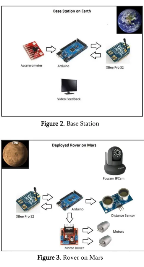
microcontroller. A video feed back monitor will be available to track the movements of the rover. [18-20]
Figure 2. Base Station
Figure 3. Rover on Mars
The XBee Pro S2 in the receiver end is configured as coordinator for receiving the data send from the base station xbee. The Arduino is programmed to avoid collision using the ultrasonic distance sensor. If the distance is less than 30cm the rover will be stopped. Arduino is programmed to control the motor driver L298D for the differential drive of the six wheeled rover. Wireless WIFI router is combined with the 360 degree Foscam to send the video back to the base station. The video will be displayed in the video feedback monitor available in the base station.
The figure 3 shows the final prototype of the mini rover.[20-21]
IV.DRIVE SYSTEM
The design of the rover has been equipped with a total of six independently driven wheels. Each wheel will have its own drive motor. The use of six wheel drive will assure that the rover keeps in contact with the ground even in the case of rough terrain. Individual motors will be chosen to simplify the drivetrain design and reduce the number of mechanical parts needed to run the system efficiently. Additionally this approach makes the rover less vulnerable to damage and offers a greater chance of recovery in the event of motor failure. The steering mechanism will be made applicable for the front and rear wheel. They will also work in conjunction with variable speed mechanisms. The figure 3 also illustrates the concept of driving the rover motors.
Figure 4. Rover on Mars
Using planetry motor datasheet, calculation for the motor requirement were made based on the entire rover system.Adding all the torque acting on the system produce the following equation [4]
Tsystem =JL.α + TL + TBR +TACC
Tsystem =Total required torque
TACC= Acceleration torque of the system
TBR=Breakaway torque of the motor
TL=Torque required by the load
JL= Moment of intertie of the load α =Angular acceleration of the system
Taking into account the number of wheels producing the torque, the torque needed from each wheel can be found by dividing Tsystem by six.This shows that the
torque per wheel must be 1/6 of Tsystem, which is the
reuired torque of the motor.
V. KINECT CONTROLLED ROBOTIC ARM
Our hands have been endowed with the capacity to handle any kind of object no matter how small or big, regular or irregular, light or heavy, it is. This capability is of utmost necessity while handling unexpected and foreign elements. For this purpose, a robotic arm similar to a human arm, with the same degrees of freedom should be used. Controlling such a system is extremely difficult using the ordinary
remote control systems. The problem is resolved, in this rover using of the feature of Microsoft Kinect, a state of the art image processing device. The gestures captured by the Kinect, located at the station, are translated into control signals that are used to control several motors that drive the robotic arm, attached to the rover. This provides an actual replication of the arm movement giving the robotic arm the same robustness and dexterity as that of a human arm. [23]
Figure 5. (a) Basic model of the Haptic arm at resting position. (b) Haptic Arm implemented with
cutter blade replicating normal lifting of arm. (c) Haptic Arm replicating more complex movement of
the arm involving all the degree of freedom
The design of the arm has been made in such a way that it occupies minimum space by folding upon itself, while not in use. On the other hand, when fully extended it can reach out to quite a large spread of space. This design of the robotic arm is such that it allows the rover access to areas like holes, or steep landscapes where the rover may not be able to physically travel. Activities like collecting samples, testing ground etc. in confined spaces can hence be done using the robotic arm. Figure5 (a) shows the model of the haptic arm whose base could be aligned parallel to the body of the rover to minimize the area while not in use. When the arm is required, it takes the position as shown in the Figure 5.
The Kinect control of the arm makes the system more user friendly although the complexity increases. The
same, an algorithm involving the use of 3D coordinate geometry is used. For greater precision in gesture control, all the reference points and angles are taken with reference to points within the human body. This means that even when the controller’s
body is not facing the Kinect, a calculated detection of the referance points as decided by the system allows the Robotc arm to replicate the gesture with great precision.
Figure 5. Skeletal image obtained with Kinect SDK
The above figure 5. shown image illustrates how a skeletal image is obtained using the Kinect SDK. This skeletal image contains many joints and links. Using the joints mainly focussed in the arm region, we are able to extract the necessary data to be sent to the microcontroller that controls the robotic arm. This data can be in the form of angles.The use of the Skeletal image ensures the exactness of measurement and the proper transfer of data from the earth station
to the rover’s robotic arm module.
Apart from the Kinect used to control the robotic arm, another Kinect is mounted in front of the rover whose angle of image capture can be adjusted to different angles so as to face the ground or remain paraller to the body of the rover as the situation demands it. This is useful for two purposes – (i) it could scan the ground for irregularities and make the adjustments in the suspension and braking system.
This allows the rover to perform in an autonomous and stable fashion without compromising on its precesion (ii) the Kinect’s 3D scanning capability con be used for studying any foreign object by making a 3D image of the selected object which is held in position by the robotic arm as shown in figure 6.[24]
Figure.6 (a) KINECT Sensor (b) KINECT Angle Adjustments (c) Ground Scanning for suspension control (d) 3D Scanning
The first segment involves the calculation and transfer of information from the base station to the rover via a satellite. First, the Kinect sensor is initialized at the base station by adjusting the position, and customizing the sensor data according to our demands. [25] This is followed by the initialization of the Graphical user interface. This means the detection of the skeletal image of the user’s arm and
rover, these control signals are channeled to the respective motor control drivers. These motors drivers rotate the motor to attain the precise position. The figure 7 shows the Kinect control flow chart.[26]
The Kinect has several advantages when compared to stereoscopic cameras. Stereoscopic Camera provide a three dimensional visual image of the environment. However, this is not enough for automation of the system. The stereoscopic camera output includes inputs from two different cameras kept a two separate positions (corresponding to angles with respect to a point) focusing a certain point. Analyzing these two frames for study of the external environment is highly impractical.
Figure 7. Kinect Control Flow Chart
The 3D scanning feature of KINECT allows us to directly scan the immediate surrounding or any object thus allowing an easy understanding of the
object or the environment. This helps in automation of the rover. The 3D scanning of the ground gives us a precise data regarding the topography of the immediate environment, so that the suspension of the
rover’s wheel system can be adjusted to maintain the
stability of the rover without. The detailed study of an environment includes understanding the texture, shape and size of the objects found in that environment. A 3D model of any object can be made using 3D scanning feature of the KINECT. Reconstruction of the scanned fragments, which saves the texture, color, shape and size can be used for further study. These factors contribute to favor the use of the KINECT when compared to a Stereoscope, for the intended purposes.
VI.POWER SYSTEM
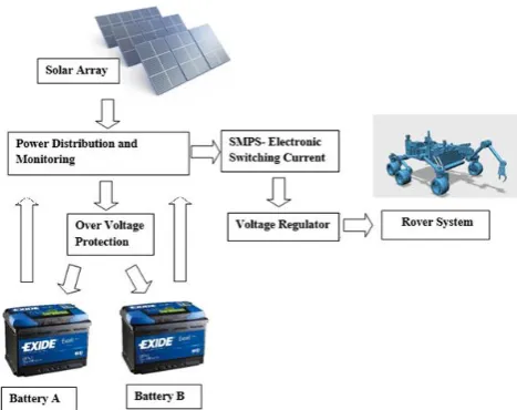
The total power system is divided into various blocks: solar cell array, power distribution and monitoring, over voltage protection, high current electronic switching device, voltage regulator, batteries. The system is designed for both power supply and backup power. Two batteries are used for this purpose. While one battery is recharging from the solar array through power monitoring and charging control the other one supplies main power for the rover system. The solar array used is 100W cadmium telluride solar panel array because its 13.5% efficient than other panels and heat resistance. The voltage from the panel is always constant in spite of changing climatic condition. The charging time calculation is done using the luminosity in alien planet. The figure 8 shows the flow chart of power monitoring and distribution system.
Power monitoring and distribution system a microprocessor based unit designed to timely control the charging and supply power to the rover system. This system charges the batteries using a technique called trickle charging to keep the battery’s charge
and provides it with a longer life cycle. Charging the battery whenever power is available or between partial discharges rather than waiting for the battery to be completely discharged. It is used with batteries in cycle service, and in applications when energy is available only intermittently.
Then the power from the batteries are drawn into high current electronic switching system (basically SMPS). This power is made available to the rover system at various ranges. Lower voltages like 3.3v to 5 v are provided for the integrated sensors and higher voltages are provided for microcontrollers and SBC (single board computers, raspberry pi in this case) and some other high power devices. To minimize wastage of energy like in linear power supply systems, the switching-mode supply continually switches between low-dissipation, full-on and full-off states spending very little time in high dissipation transition. Voltage regulation is done by varying the duty cycle of the switching i.e. ratio of on-to-off time. The advantage of switched-mode power supply is higher power conversion efficiency. It is also amounts to a smaller and lighter system when compared to a linear supply due to the smaller transformer size and weight.
Figure 8. Power monitoring and distribution system flow chart
VII. Application
The rover design that has been proposed in this paper has a number of applications particularly in space and deep sea explorations. In this paper we have discussed the application of the rover design in the exploration of alien planets. Undoubtedly the rover can be used for landscape mapping, discovering new landmarks in alien landscapes, examination of mineral content, detection of water etc. This can be done by installing the necessary detection systems and sensors associated with it, on the rover. In dedicated applications such landscape mapping the Kinect sensor installed on the rover can be used. Additional sensors can also be installed to increase the accuracy of the mapping. Algorithms can be implemented to detect a particular landscape by a comparison and detection mechanism. This could even be extended to a search to find the most inhabitable space in planets like mars where human exploration is imminent in the near future.
The detection of mineral content can be executed with much better accuracy in the proposed rover design when compared to previous designs. The use of the robotic arm to collect samples is a significant advantage. Water detection which of particular interest in detection of life, can also be done by installing the necessary detection systems on board. The availability of a humanoid bot on board the rover is a particularly useful feature. It essentially makes the exploration more human-based than ever before.
VIII. CONCLUSION
flexible segmented body, embedded multipurpose robotic arm, multi wheel mechanism and Kinect module integration for advanced image processing, contribute to its improved functionality and flexibility of its overall design. The system control, done using the Arduino microcontroller and the Raspberry pi microprocessor makes the design feasible and easy to implement. The array of sensors used in the rover act to form an efficient sensory information base which is used by the rover to achieve a number function including a reflex mechanism for greater safety. This essentially opens up the possibilities of alien planet explorations and can potentially increase the information we have about these planets manifold.
Considering the many improvements that have been made in this proposed design when compared to other designs the possibilities of this rover are too many to enumerate briefly. To improve its functionality in landscape mapping long range cameras can be installed with image processing technology like the Kinect. This could greatly increase the range and depth of the landscape mapping process. Algorithms can be implemented to detect a particular landscape, compare it to existing data stored in a memory and conclude if new sites have been found. Mineral content detection can be improved by using superior equipment and necessary detection mechanisms. The mineral testing can be done by either installing an immobile testing unit, remotely connected to the base station as well the rover, and supplying the collected samples as and when required . Otherwise a more efficient approach can be taken by installing a system on board the rover for preliminary detection and allowing detailed testing to happen elsewhere. The availability of the humanoid bot allows a lot of improvements to be made in the overall design depending on the type of mission. The bot can also be equipped to make repairs and set up bases on alien land which can also help in
the other functions that the rover is designed to Bones. (2001). Science @ NASA. 4 May, 2002.
[4] "Eating Right For Long-Duration Space
Missions." Eating Right For Long-Duration Space Missions. Web. 10 Mar. 2016.
[5] Pierson DL, Mehta SK, Magee RR, Mishra SK. Person-to-person transfer of Candida albicans in the space environment. J Med & Vet Mycol 1994; 33: 145-50
[6] Suresh A. et al. (2017) An Advanced Spider-Like
Rocker-Bogie Suspension System for Mars Exploration Rovers. In: Kim JH., Karray F., Jo J., Sincak P., Myung H. (eds) Robot Intelligence Technology and Applications 4. Advances in Intelligent Systems and Computing, vol 447. Springer, Cham
[7] Aswath S. et al. (2015) An Intelligent Rover Design Integrated with Humanoid Robot for Alien Planet Exploration. In: Kim JH., Yang W., Jo J., Sincak P., Myung H. (eds) Robot Intelligence Technology and Applications 3. Advances in Intelligent Systems and Computing, vol 345. Springer, Cham
[8] Pierson DL, Mehta SK, Magee RR, Mishra SK. Person-to-person transfer of Candida albicans in the space environment. J Med & Vet Mycol 1994; 33: 145-50
[10] Dunbar, Brian. "Cardiovascular System Gets 'Lazy' in Space; New Study Gets Blood Flowing on Station." NASA. NASA, 2007. Web. 13 Mar. 2016.
[11] “Scientists Ponder the Brain in Space.”nasa.gov.
Web. 13 Mar. 2016.
[12] Ball, John, and Charles H. Evans. Safe Passage: Astronaut Care for Exploration Missions. Washington, D.C.: National Academy, 2001. Print.
[13] Aswath Suresh, Gautam Ranjan,Sri Harsha,
Kolluri Surya, Adarsh Ranjan, Nitin Ajithkumar, Sajin Sabu,Vinay Teja, Abel Varghese David,
Ganesha Udupa, “Innovative Low Cost Mars Flyby Spacecraft for Safe Interplanetary Human
Mission”,Mars Society Convention,
Marspapers,2016
[14] Aswath Suresh, Sri harsha,Kolluri Surya,Debrup
Laha,Dhruv Gaba,Shivam Bhardwaj,Vinay Teja,Siddhant Bhambri and Suvaansh Bhambri,
“Innovative Human Mars Mission with Vertical
Farming” ,Mars Society Convention,Marspapers,2017
[15] Aswath Suresh, Sri Harsha,Kolluri Surya,Debrup
Laha,Dhruv Gaba,Siddhant Bhambri,Suvaansh
Bhambri and Karthik Rangarajan, “Exploration
-Probe to Jupiter Moon Europa”, Mars Society Earthscan Press. pp. 283–314
[17] Plotnick, Roy E. (1 January 1980). "Relationship between biological extinctions and geomagnetic reversals". Geology
[18] Aswath, S., Tilak, C.K., Sengar, A., Udupa, G.: Design and development of Mobile Operated Control System for Humanoid Robot. In: Advances in Computing, 3rd edn., vol. 3, pp. 50–
56
[19] Aswath, S., Tilak, C.K., Suresh, A., Udupa, G.: Human Gesture Recognition for Real-Time Control of Humanoid Robot. In: Proceedings of International Conference on Advances in Engineering and Technology, Singapore, March 29-30 (2014)
[20] Krishnan, A.B., Aswath, S., Udupa, G.: Real Time Vision Based Humanoid Robotic Platform for Robo Soccer Competition. In: Proceedings of International Conference on Interdisciplinary Advances in Applied Computing, India, October 10-11 (2014)
[21] Suresh A., Sridhar C.P., Gaba D., Laha D., Bhambri S. (2019) Design and Development of Intelligent Self-driving Car Using ROS and Machine Vision Algorithm. In: Kim JH. et al. (eds) Robot Intelligence Technology and Applications 5. RiTA 2017. Advances in Intelligent Systems and Computing, vol 751. Springer, Cham
[22] Suresh A., Laha D., Gaba D., Bhambri S. (2019) Design and Development of Innovative Pet Feeding Robot. In: Kim JH. et al. (eds) Robot Intelligence Technology and Applications 5. RiTA 2017. Advances in Intelligent Systems and Computing, vol 751. Springer, Cham
[23] Bhardwaj S. et al. (2019) Isolated
Bio-Regenerative System for Vertical Farming Through Robots in Space Explorations. In: Kim JH. et al. (eds) Robot Intelligence Technology and Applications 5. RiTA 2017. Advances in Intelligent Systems and Computing, vol 751. Springer, Cham
[24] Suresh A., Gaba D., Bhambri S., Laha D. (2019) Intelligent Multi-fingered Dexterous Hand Using Virtual Reality (VR) and Robot Operating System (ROS). In: Kim JH. et al. (eds) Robot Intelligence Technology and Applications 5. RiTA 2017. Advances in Intelligent Systems and Computing, vol 751. Springer, Cham
[25] Kumar V.S., Aswath S., Shashidhar T.S.,
Length Prosthetic Robotic Arm for the Disabled. In: Kim JH., Karray F., Jo J., Sincak P., Myung H. (eds) Robot Intelligence Technology and Applications 4. Advances in Intelligent Systems and Computing, vol 447. Springer, Cham
[26] Suresh A., Arora C., Laha D., Gaba D., Bhambri
S. (2019) Intelligent Smart Glass for Visually Impaired Using Deep Learning Machine Vision Techniques and Robot Operating System (ROS). In: Kim JH. et al. (eds) Robot Intelligence Technology and Applications 5. RiTA 2017. Advances in Intelligent Systems and Computing, vol 751. Springer, Cham
Cite this article as :
Muhammed Sharukh, Badsha Karim, Sajin NV, Jameson Thomas, "Intelligent Deployable Mini Rover from the Mars Rover for Deep Narrow Scientific Investigation", International Journal of Scientific Research in Computer Science, Engineering and Information Technology (IJSRCSEIT), ISSN : 2456-3307, Volume 5 Issue 3, pp. 174-184, May-June 2019.
Available at doi :
https://doi.org/10.32628/CSEIT195362