Multiple-Constraint Synthesis of Rotationally Symmetric Sparse
Circular Arrays Using a Hybrid Algorithm
Rui-Qi Wang* and Yong-Chang Jiao
Abstract—Rotationally symmetric sparse circular arrays are synthesized under multiple constraints. By combining the modified differential evolution algorithm based on the harmony search (in short HSDE) with the vector mapping (VM) method, a hybrid algorithm, called VM-HSDE, is proposed for synthesizing sparse circular arrays with low sidelobe levels. Due to the array’s specific geometry, the number of optimization variables is reduced, and the constrained optimization problem is simplified. Moreover, infeasible solutions are avoided, and the problem is effectively solved by the VM-HSDE algorithm. Finally, three pattern optimization results verify the effectiveness and reliability of the VM-HSDE algorithm.
1. INTRODUCTION
Sparse circular planar array (SCPA) is a planar array whose elements arbitrarily are distributed over a circular aperture. In recent years, design of the SCPA geometry under multiple constraints for desired performance has attracted considerable interest in various applications [1–13]. As one kind of SCPAs, a concentric circular antenna array (CCAA) has several concentric rings with different radii and uniform or nonuniform element spacings, which has been widely studied in [1–7]. To exploit various geometries of other types of SCPAs, the array based on aperiodic tilings [8], the array composed of subarrays [9], and the array with rotational symmetry structure [11] have been investigated.
The geometry design of such arrays involves several constraints, such as the number of array elements, aperture size, and the minimum spacing between two adjacent elements. By enforcing a minimum element spacing ofbλH (b≥0.5, λH is the wavelength in vacuum at the highest frequency),
Gregory et al. utilized rotational symmetry structure [11] of the aperiodic array to avoid grating lobes over a bandwidth of 2b : 1. At the lowest frequency, the minimum element spacings are typically constrained to 0.5λL (λL is the wavelength in vacuum at the lowest frequency, and λL = 2bλH) to
avoid mutual coupling. Rotational symmetry layouts with several constraints provide great flexibility in the pattern synthesis and contribute to complicated optimization problems, particularly for large scale broadband arrays.
Various optimization methods have been reported to synthesize sparse circular arrays in [14–22], including analytical techniques and evolutionary algorithms. In [14] and [15], the vector mapping (VM) method and matrix mapping method were used to handle complicated constraints for linear and planar arrays, respectively. With the help of these methods, infeasible solutions are avoided, and the total search space is effectively reduced. However, the complicated constraints for the SCPA synthesis are rarely discussed. In a recent study by Chen et al., a modified real genetic algorithm (MGA) was introduced to design a sparse circular array [7]. A peak sidelobe level (PSLL) of −23.7424 dB for a
Received 10 December 2018, Accepted 8 February 2019, Scheduled 12 February 2019
* Corresponding author: Rui-Qi Wang ([email protected]).
201-element array was obtained. A hybrid BCS-deterministic approach [4] was presented to synthesize CCAA, and the optimized 201-element array has the PSLL of−22.94 dB.
In this paper, a rotationally symmetric sparse circular array (RSSCA) with all elements uniformly excited is synthesized. The array has a fixed number of elements distributed over a given array aperture with the minimum spacing constraint. By combining a modified differential evolution algorithm based on harmony search (HSDE) [18] with the vector mapping (VM) method, a hybrid algorithm, called VM-HSDE, is proposed. The VM-HSDE algorithm is used to optimize the RSSCA geometry with the objective of PSLL reduction. To prove the effectiveness and reliability of the proposed algorithm, three different arrays are synthesized, and the results are compared to those obtained by the MGA [7], multi-objective evolutionary algorithm (MOEA) [10], and covariance matrix adaptation evolutionary strategy (CMA-ES) [11], respectively. The proposed algorithm converges fast for synthesizing the RSSCAs, which could be effectively performed for optimizing large scale arrays.
This paper is organized as follows. The geometry of RSSCA and the VM-HSDE algorithm are introduced in Section 2, where the synthesis is mathematically formulated as a constrained optimization problem. In Section 3, numerical experiments are performed with results discussed. Finally, conclusions are drawn in Section 4.
2. ROTATIONALLY SYMMETRIC SPARSE CIRCULAR ARRAY SYNTHESIS
2.1. Array Geometry and Formulation
Consider the rotationally symmetric sparse circular array with all elements uniformly excited. As illustrated in Fig. 1, the array has a circular aperture with radiusR and a P-fold rotational symmetry structure with Δϕ= 2π/P. The full array has N elements, and each slice hasM elements, M =N/P. To keep the spacing between the center element and the adjacent element no less thandmin, a circular region of radius d1 (greater than dmin) is segmented. Then, each slice is divided into Q annular regions with corresponding M1, M2, . . ., MQ elements, and
Q
i=1Mi = M. Referring to Eq. (6)
in [7], ki elements are arranged in the ith ring with the adjacent element spacings no less than dmin. ki = Int2πLi/dmin, where Li is the radius of the ith ring, and Int· indicates rounding down. To
keep the spacings between elements no less thandmin for the RSSCA shown in Fig. 1, the radius of the
ith ring satisfiesLi ≥idmin. The number of elements in the ith annular region is set as a nonnegative
integer, which satisfies the constraint Mi≤Int2πi/P.
In Fig. 1, element (i, j) represents the jth element within the ith annular region in the first slice, where j = 1,2, . . . , Mi, i = 1,2, . . . , Q. Element (i, j) is located at (ri,j, ωi,j) in the polar
coordinate system with the origin O, which is represented by vector ai,j = (ri,j, ωi,j). We have ri,j = Li + Δi,j =
i
s=1ds+ Δi,j, where Li denotes the radius of the ith ring, and Δi,j and ωi,j
denote the radial perturbation and the azimuth angle of element (i,j). Also,d1=L1,di =Li−Li−1, i= 2,3, . . . , Q,di represents the radial distance between the (i−1)th ring and theith ring.
Define vectors
d= (d1, d2, . . . , dQ)T
Δ=Δ{1},Δ{2}, . . . ,Δ{Q} T
ω=ω{1}, ω{2}, . . . , ω{Q}
T (1)
Both Δ and ω are divided into Q segments. Their segments are denoted by Δ{i} = (Δi,1, . . . ,Δi,j, . . . ,Δi,M i), ω{i} = (ωi,1, . . . , ωi,j, . . . , ωi,M i), j = 1,2, . . . , Mi, i = 1,2, . . . , Q. Then
the radiation pattern of the RSSCA is expressed as
F(θ, ϕ,d,Δ,ω) =
P−1
p=0 Q i=1 Mi j=1
ejk(is=1ds+Δi,j)sinθcos(ωi,j+pΔϕ−ϕ) (2)
wherekis the free space wave number, andθandϕare the elevation and azimuth angles. For theP-fold rotationally symmetric array, the associated radiation pattern possessesϕ-symmetry of the angle of Δϕ
or Δϕ/2 whenP is even or odd, respectively. Thus, onlyF(θ, ϕ,d,Δ,ω) values in region{0≤θ≤π/2, 0≤ϕ≤Δϕ} or region{0≤θ≤π/2, 0≤ϕ≤Δϕ/2} need to be computed, depending on the odevity of P [11].
The fitness function is defined as the PSLL of the radiation pattern in theϕ-plane within the angle of Δϕor Δϕ/2 as follows.
fitness (d,Δ,ω) = max
(θ,ϕ)∈L(d,Δ,ω)
F(θmax, ϕmax,F(θ, ϕ,d,Δd,,ωΔ),ω) (3) where (θmax,ϕmax) denotes the maximum radiation direction of patternF(θ, ϕ,d,Δ,ω), andL(d,Δ,ω) denotes the sidelobe region corresponding tod, Δandω.
2.2. Optimization Model
For the RSSCA described above, the synthesis problem is summarized as: finding optimal vectors d∗, Δ∗, and ω∗ such that fitness(d,Δ,ω) in Eq. (3) is minimized, under the constraints of aperture size and minimum element spacing. Thus, the following constrained optimization model is established.
minimize fitness (d,Δ,ω)
subject to di≥dmin, Q
i=1
di=R−dmin
0≤Δi,j ≤dmin, Δi,j−Δi−1,k ≥0
0≤ωi,j≤Δϕ, ωi,j+1−ωi,j ≥εi
j = 1,2, . . . , Mi, k= 1,2, . . . , Mi−1, i= 1,2, . . . , Q
(4)
wheredmin is the minimum bound for the spacing between two adjacent elements, which determines the array bandwidth; εi is the minimum angular separation of theith ring, which is calculated according
to the following relation
εi = arccos ⎡ ⎢ ⎢ ⎢ ⎢ ⎢ ⎣
1− d
2 min 2 i s=1 ds 2 ⎤ ⎥ ⎥ ⎥ ⎥ ⎥ ⎦, i
Denote the distance between elements (i+ 1, j) and (i, k) distributed in two adjacent annular regions by|ai+1,j−ai,k|, and the distance between two adjacent elements (i,j+ 1) and (i,j) in theith
annular region by|ai,j+1−ai,j|. Obviously,
|ai+1,j−ai,k| ≥ ||ai+1,j| − |ai,k||=di+1+ (Δi+1,j−Δi,k)≥dmin
j= 1,2, . . . , Mi+1, k= 1,2, . . . , Mi, i= 1,2, . . . , Q−1 (6)
|ai,j+1−ai,j| =
ri,j2 +1+ri,j2 −2ri,j+1ri,jcos (ωi,j+1−ωi,j)
≥ri,j2 +1+ri,j2 −2ri,j+1ri,jcosεi≥
ri,j2 +1+r2i,j
(1−cosεi)
≥2L2i (1−cosεi) =dmin j= 1,2, . . . , Mi−1, i= 1,2, . . . , Q (7)
and
|ai,j| = ri= i
s=1
ds+ Δi,j ≤ Q
s=1
ds+ Δi,j =R−dmin+ Δi,j ≤R
j = 1,2, . . . , Mi, i= 1,2, . . . , Q (8)
Through basic mathematical relations in Eqs. (6), (7) and (8), we prove that both the element spacing and aperture constraints are satisfied for vectorsd,Δ, ωin Eq. (4).
2.3. The VM-HSDE Algorithm
First, according to the VM method, a projection equation between two vectorsxandx is summarized as follows, which is given by Equation (6) in [14].
x = VM (x)
where x= (x1, x2, . . . , xn)T, x = (x1, x2, . . . , xn)T
min≤xi, xi ≤max, i= 1,2, . . . , n n
s=1
xs=L
(9)
Then, set
y= VM (x1), z= VM (x2)
x1 = (x11, x12, . . . , x1n1)T, y= (y1, y2, . . . , yn1)T
x2 = (x21, x22, . . . , x2n2)T, z= (z1, z2, . . . , zn2)T
min1≤x1i, yi≤max1, i= 1,2, . . . , n1
min2≤x2i, zi ≤max2, i= 1,2, . . . , n2 n1
s=1
ys=L1, n2
s=1
zs=L2
(10)
wheren1 =Q, min1 =dmin, max1 = 2dmin,L1=R−dmin,n2=Mi, min2=εi, max2= 2εi,L2= Δϕ.
Vector d and theith segment of vector ω are obtained by d=y
ωi,j = j
s=1
zs−δ·z1, j= 1,2, . . . , n2 (11)
whereωi,j is the jth element of ω{i},δ an uniform random number in [0, 1], andz1 the first element of
vector z.
less computation in [18]. Here, we propose the VM-HSDE algorithm based on the HSDE algorithm. Two modifications are added in the six steps of the HSDE. d, Δ and ω are set as the optimization variables. In Step 1, the initial population with N P individuals (ds,Δs,ωs), s = 1,2, . . . , N P is
generated. Randomly choose 0≤Δs
i,j ≤dminand rearrange it to satisfy the conditions Δsi,j−Δsi−1,k≥0, j = 1,2, . . . , Mi, k= 1,2, . . . , Mi−1,i= 2,3, . . . , Q. ds and ωs are generated by Equation (11) such
that all constraints in Eq. (4) are satisfied. The second modification is to add an operation at the end of Step 3, in whichds andωs are evaluated and updated by Eq. (11).
With the help of the RSSCA specific geometry and VM-HSDE algorithm, the constrained optimization problem in Eq. (4) is effectively simplified. On the one hand, due to rotational symmetry structure, the number of variables is reduced, and the computing scale of the radiation pattern is simplified. On the other hand, the generation scheme of the sparse circular array by the MGA [7] is to thin the elements of the fullest array. It is hard to perform MGA for the large scale array because the total element number of the fullest array and the number of the abandoned elements are extremely large. The VM-HSDE algorithm for synthesizing the RSSCA can avoid this drawback, which could be effectively applied to large scale array optimization.
3. NUMERICAL RESULTS
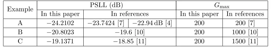
In this section, three RSSCA examples with constraints of the element number, aperture size and minimum element spacing are presented. Examples A, B, and C are taken from [7, 10, 11], respectively. The detailed design parameters for these examples are given in Table 1. In the VM-HSDE algorithm, we use the same values ofHR,CRmax,CRmin,Fmax, andFmin as given in [18]. For all computer simulation
examples, 10 independent runs are performed, and the algorithm is terminated after Gmax = 200 generations for each run. The population size of each example is set the same as that in the corresponding compared reference. The angle resolutions ofθandϕ(0≤θ≤π/2, 0≤ϕ≤Δϕ/2, with oddQ) are set as 0.2◦ for Example C, while 1.8◦ is used for Examples A and B, which are adopted by the compared references. Table 2 gives the best PSLL values and maximum generations Gmax for all examples, compared to those available in [7, 10, 11], which demonstrates effectiveness of the VM-HSDE algorithm. Example A is a 201-element uniformly excited array with a single element fixed at the center. The numbers of variables for the proposed algorithm and MGA [7] are 89 and 231, respectively. Obviously, the number of optimization variables is effectively reduced. The optimized 201-element uniformly excited
Table 1. Design parameters.
Example Design Parameters
A N = 201, P = 5, Q= 9, {M1, M2, . . . , MQ}={1,2,3,5,6,5,5,6,7}
R= 5λ,dmin= 0.5λ
B N = 80, P = 5, Q= 5, {M1, M2, . . . , MQ}={1,2,3,4,6}
R= 3.8λ, dmin = 0.5λ
C N = 600, P = 15, Q= 16, {M1, M2, . . . , MQ}={0,0,1,1,2,2,2,2,3,3,3,3,4,4,5,5}
R= 100λ,dmin = 5λ
Table 2. Comparative convergence performances for three examples.
Example PSLL (dB) Gmax
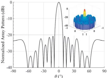
arrays by the MGA and the hybrid BCS-deterministic approach [4] have PSLLs of −23.7424 dB and −22.94 dB, respectively. Fig. 2 shows the element layout of the best solution obtained by the VM-HSDE algorithm. The 3-D radiation pattern and theϕ-cut pattern corresponding to the peak sidelobe level are given in Fig. 3, where the PSLL is −24.2102 dB. Comparing the PSLL results obtained by VM-HSDE and MGA, an improvement of 0.4678 dB is observed.
Example B is an 80-element uniformly excited array with an aperture radius of 3.8λ. In [10], the array was synthesized by the MOEA in 1000 generations for 100 independent runs, which is an extremely large amount of computation. The numbers of variables for the proposed algorithm and MOEA are 37 and 17. The best PSLL of −19.6 dB is obtained for this case. By using the VM-HSDE algorithm, the best array yields the PSLL of −20.8023 dB in 200 generations for 10 independent runs. It is obvious that the proposed algorithm converges fast with good optimization results. Fig. 4 shows the geometry of the best solution. The 3-D radiation pattern and the ϕ-cut pattern corresponding to the peak sidelobe level are given in Fig. 5.
Example C is a relatively large scale array with large element spacing. The detailed design parameters are shown in Table 1. The numbers of variables for the proposed algorithm and
CMA-Figure 2. Geometry of the best array for Example A.
Figure 3. ϕ-cut pattern corresponding to the peak sidelobe level and 3-D Pattern for Example A.
Figure 4. Geometry of the best array for Example B.
Figure 6. Geometry of the best array for Example C.
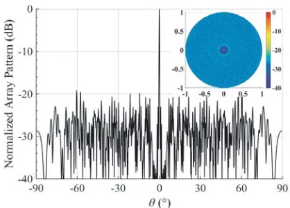
Figure 7. ϕ-cut pattern corresponding to the peak sidelobe level and 3-D Pattern for Example C.
ES [11] are 96 and 80, respectively. Fig. 6 shows the array geometry of the best solution obtained by the VM-HSDE algorithm in 200 generations. The 3-D radiation pattern and the ϕ-cut pattern corresponding to the peak sidelobe level are given in Fig. 7. The best PSLL is −19.1371 dB, which is 0.2871 dB lower than that obtained by the CMA-ES in 1500 generations. In [11], less than −18.9 dB PSLLs over a 5.4 : 1 bandwidth have been achieved. By enforcing a minimum spacing of 5λ (λ is the wavelength at the highest frequency), the best array obtained by the VM-HSDE algorithm provides less than −18.6 dB PSLLs without grating lobes over a wider bandwidth of 10 : 1. It is noted that the VM-HSDE algorithm is effective for synthesizing the large scale broadband arrays.
4. CONCLUSIONS
A hybrid algorithm of the vector mapping and optimizer HSDE is applied to synthesizing rotationally symmetric sparse circular arrays. With a fixed number of elements distributed over a given aperture, element locations are optimized to obtain low PSLL under the minimum spacing constraint. Three examples are given and compared to the references. Numerical results show that the VM-HSDE algorithm converges fast with better optimization results than that obtained by the MGA, MOEA, and CMA-ES.
ACKNOWLEDGMENT
This work was supported in part by the National Key Research and Development Program of China (Grant 2017YFB0202102).
REFERENCES
1. Haupt, R., “Optimized element spacing for low sidelobe concentric ring arrays,” IEEE Trans. Antennas Propag., Vol. 56, No. 1, 266–268, 2008.
2. Jiang, Y. and S. Zhang, “An innovative strategy for synthesis of uniformly weighted circular aperture antenna array based on the weighting density method,”IEEE Antennas Wireless Propag. Lett., Vol. 12, 725–728, 2013.
3. Jiang, Y., S. Zhang, Q. Guo, and M. Li, “Synthesis of uniformly excited concentric ring arrays using the improved integer GA,”IEEE Antennas Wireless Propag. Lett., Vol. 15, 1124–1127, 2016. 4. Zhao, X., Q. Yang, and Y. Zhang, “A hybrid method for the optimal synthesis of 3-D patterns of
5. Carlin, M., G. Oliveri, and A. Massa, “Hybrid BCS-deterministic approach for sparse concentric ring isophoric arrays,” IEEE Trans. Antennas Propag., Vol. 63, No. 1, 378–383, 2015.
6. Ram, G., D. Mandal, R. Kar, and S. P. Ghoshal, “Cat swarm optimization as applied to time-modulated concentric circular antenna array: Analysis and comparison with other stochastic optimization methods,”IEEE Trans. Antennas Propag., Vol. 63, No. 9, 4180–4183, 2015.
7. Chen, K., H. Chen, L. Wang, and H. Wu, “Modified real GA for the synthesis of sparse planar circular arrays,”IEEE Antennas Wireless Propag. Lett., Vol. 15, 274–277, 2016.
8. Spence, T. G. and D. H. Werner, “Design of broadband planar arrays based on the optimization of aperiodic tilings,”IEEE Trans. Antennas Propag., Vol. 56, No. 1, 76–86, 2008.
9. Alvarez-Folgueiras, M., J. Rodriguez-Gonzalez, and F. Ares-Pena, “High-performance uniformly excited linear and planar arrays based on linear semiarrays composed of subarrays with different uniform spacings,” IEEE Trans. Antennas Propag., Vol. 57, No. 12, 4002–4006, 2009.
10. Bianchi, D., S. Genovesi, and A. Monorchio, “Constrained Pareto optimization of wide band and steerable concentric ring arrays,”IEEE Trans. Antennas Propag., Vol. 60, No. 7, 3195–3204, 2012. 11. Gregory, M. D., F. A. Namin, and D. H. Werner, “Exploiting rotational symmetry for the design of ultra-wideband planar phased array layouts,” IEEE Trans. Antennas Propag., Vol. 61, No. 1, 176–184, 2013.
12. El-makadema, A., L. Rashid, and A. K. Brown, “Geometry design optimization of large scale broadband aperture array systems,” IEEE Trans. Antennas Propag., Vol. 62, No. 4, 1673–1680, 2014.
13. Clavier, T., et al., “A global-local synthesis approach for large non-regular arrays,” IEEE Trans. Antennas Propag., Vol. 62, No. 4, 1596–1606, 2014.
14. Lin, Z.-Q., W.-M. Jia, M.-L. Yao, and L.-Y. Hao, “Synthesis of sparse linear arrays using vector mapping and simultaneous perturbation stochastic approximation,” IEEE Antennas Wireless Propag. Lett., Vol. 11, 220–223, 2012.
15. Liu, H., H. Zhao, W. Li, and B. Liu, “Synthesis of sparse planar arrays using matrix mapping and differential evolution,”IEEE Antennas Wireless Propag. Lett., Vol. 15, 1905–1908, 2016.
16. Wang, X.-K., Y.-C. Jiao, Y. Liu, and Y. Y. Tan, “Synthesis of large planar thinned arrays using IWO-IFT algorithm,” Progress In Electromagnetics Research, Vol. 136, 29–42, 2013.
17. Elsaidy, E. I., M. I. Dessouky, S. Khamis, and Y. A. Albagory, “Concentric circular antenna array synthesis using comprehensive learning particle swarm optimizer,” Progress In Electromagnetics Research Letters, Vol. 29, 1–13, 2012.
18. Zhang, F., W. Jia, and M. Yao, “Linear aperiodic array synthesis using differential evolution algorithm,”IEEE Antennas Wireless Propag. Lett., Vol. 12, 797–800, 2013.
19. Singh, U. and M. Rattan, “Design of thinned concentric circular antenna arrays using firefly algorithm,”IET Microw. Antennas Propag., Vol. 8, 894–900, 2014.
20. Cao, A., H. Li, S. Ma, J. Tan, and J. Zhou, “Sparse circular array pattern optimization based on MOPSO and convex optimization,”2015 Asia-Pacific Microwave Conference (APMC), Vol. 2, 1–3, 2015.
21. Sun, G., Y. Liu, Z. Chen, S. Liang, A. Wang, and Y. Zhang, “Radiation beam pattern synthesis of concentric circular antenna arrays using hybrid approach based on cuckoo search,”IEEE Trans. Antennas Propag., Vol. 66, No. 9, 4563–4576, 2018.
22. Zhao, X., Y. Jin, H. Ji, J. Geng, X. Liang, and R. Jin, “An improved mixed-integer multi-objective particle swarm optimization and its application in antenna array design,”2013 5th IEEE International Symposium on Microwave, Antenna, Propagation and EMC Technologies for Wireless