A Flexible Frequency and Pattern Reconfigurable Antenna
for Wireless Systems
Ziqiang Zhu1, 2, Peng Wang2, 3, Sicen You1, and Peng Gao1, 3, *
Abstract—A novel flexible frequency and pattern reconfigurable antenna for wireless system is
proposed. The antenna is composed of two completely symmetrical radiating elements, a feedline
and ground. By controlling the on and off of 8 PIN diodes loaded on the symmetric hexagonal split ring and monopole branches to select the radiation element, the antenna achieves frequency reconfiguration in 1.9G band and 2.4G band, and is capable of steering the beam in two directions in each band. Meanwhile, the antenna works at four states with omnidirectional radiation patterns. Finally, the bending characteristics of the antenna at different bending degrees are analyzed. Measured results are in good agreement with simulations, which denotes that it is suitable for wireless systems.
1. INTRODUCTION
With successive development of wireless systems, flexible reconfigurable antennas have attracted much attention due to the features of flexibility and reconfigurability. Flexible material and reconfigurable antenna are combined to form a flexible reconfigurable antenna, which not only has the advantages of flexibility, good fit for the carrier, effective space saving, and small system volume, but also can use an antenna to achieve the function of multiple single antennas. Therefore, the research of flexible
reconfigurable antennas has significance in today’s complex environment. In [1], a frequency and
pattern reconfigurable antenna based on a center-shorted microstrip patch is presented. The antenna can switch its operation between two distinct configurations, namely a microstrip patch broadside pattern or an omnidirectional monopole pattern by utilizing varactors loaded with open-circuited stubs as its tuning mechanism. A novel patch antenna with frequency and pattern reconfiguration with polarization switching is proposed, which could select the rhombus-shaped radiator with three excitation lines oriented at different angles by changing the bias states of three pairs of PIN diodes [2]. A flexible reconfigurable folded slot antenna based on a flexible polyethylene terephthalate substrate is presented. The frequency and polarization reconfigurability is achieved by turning a PIN diode on and off, which alters the radiation characteristics of the stub [3]. In [4], an optically transparent, flexible, and mechanically reconfigurable zeroth-order resonant antenna using a stretchable micromesh structure is presented, and the resonant frequency of the antennas is linearly reconfigurable from 2.94 to 2.46 GHz upon stretching. A diode-switched thermal-transfer printed antenna on a flexible substrate achieves frequency reconfigurability [5]. A robust, flexible, and electronically tunable wearable antenna is designed and fabricated on a PDMS substrate, and conductive fabric is used to form the conducting parts of the antenna. The frequency-reconfigurability is achieved by means of varactors [6].
In this paper, a frequency and pattern reconfigurable antenna based on flexible materials for wireless application is proposed. By controlling PIN diodes, the proposed antenna achieves frequency
Received 4 April 2018, Accepted 10 May 2018, Scheduled 29 May 2018
* Corresponding author: Peng Gao ([email protected]).
1 Research Institute of Electronic Science and Technology, University of Electronic Science and Technology of China, Chengdu 611731,
China.2 School of Resources and Environment, University of Electronic Science and Technology of China, Chengdu 611731, China.
reconfiguration in 1.9G band and 2.4G band. When operating at 1.9G band, the antenna can switch
the pattern in the direction ofφ= 60◦ and φ= 300◦. When operating at the 2.4G band, the antenna
can switch the pattern in the direction ofφ= 34◦ and φ= 326◦. The proposed antenna with bias lines
is fabricated on a Rogers5880 substrate.
2. ANTENNA DESIGN
The frequency and pattern reconfigurable antennas are able to control the resonant frequency band and radiation direction by selecting the radiator through PIN diodes, MEMS, or varactors, which are used to dynamically change the antenna radiation performance. The dielectric substrates used for flexible antennas are textile, paper-based, polymer (polyimide, PDMS, PET, LCP, etc.), Rogers flexible substrate.
The geometry and design parameters of the proposed flexible frequency and pattern reconfigurable antenna are shown in Fig. 1. The antenna is composed of a feedline, a ground and two completely symmetrical radiating elements, wherein each radiating element comprises a circular monopole branch, a regular hexagonal open ring, and two branches are added to the ring to extend the current and lower the low frequency to get the desired frequency band, which are fabricated on a Rogers5880 substrate with a relative permittivity of 2.2 and thickness of 0.127 mm. To select the radiated element, we can control the on and off of 8 PIN diodes loaded on the symmetric radiation element. The parameters are optimized by the commercial software ANSYS high frequency structure simulator (HFSS) v15.0. The
dimensions of the flexible frequency and pattern reconfigurable antenna are: L= 44 mm, W = 42 mm,
L1 = 12 mm, W1 = 1.5 mm, L2 = 10 mm, W2 = 2 mm, L3 = 11 mm, L4 = 7 mm, W3 = 0.8 mm,
W4 = 4 mm,W5 = 4 mm,L5 = 10 mm.
Figure 1. Geometry of the flexible reconfigurable antenna.
Because the diode requires a DC bias voltage to control its ON or OFF state, bias voltages of V1 to V7 are applied. The PIN diode is SMP1345 series, and the operating frequency range is 100 MHz to 6 GHz. From the characteristic parameters of the SMP1345 079 series, the equivalent resistance of the PIN diode for the ON state is 1.5 Ω, whereas the equivalent capacitance for the OFF state is 0.19 pF. Bias voltage and the states of PIN diodes in the two modes of the antenna are displayed in Table 1. Moreover, a 470 pF Murata is mounted on the feedline to avoid DC signal flowing into the RF source of the antenna, and the maximum operating frequency of this capacitor is 8.5 GHz. In order to isolate the DC and RF signals, each bias contains an RF choke inductor L of 100 nH.
Table 1. Four modes of the proposed flexible reconfigurable antenna.
states V1 V2 V3 V4 V5 V6 V7 P1 P2 P3 P4 P5 P6 P7 P8
S1 2V 1V 0V / / / / ON ON ON OFF OFF OFF OFF OFF
S2 2V 1V / 0V / / / ON OFF OFF ON OFF OFF OFF OFF
S3 2V / / / 1V 0V / OFF OFF OFF OFF ON ON ON OFF
S4 2V / / / 1V / 0V OFF OFF OFF OFF ON OFF OFF ON
(a) (b) (c) (d)
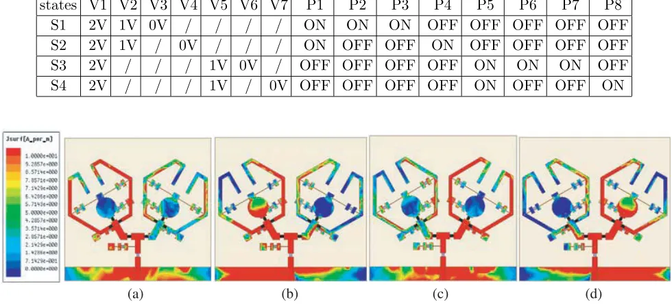
Figure 2. The current distribution in the four operating states. (a) S1. (b) S2. (c) S3. (d) S4.
3. RESULTS AND DISCUSSION
The flexible pattern reconfigurable antenna is fabricated, shown in Fig. 3. PIN diodes of SMP1345 are
soldered, which are assured by low capacitance and low resistance. TheS-parameters of the proposed
reconfigurable antenna are measured by the Agilent E8363B vector network analyzer. By controlling PIN diodes, the proposed antenna achieves frequency reconfiguration in the 1.9G band with a bandwidth of 1.84–2.00 GHz and the 2.4G band with a bandwidth of 2.27–2.49 GHz. When operating at the 1.9G
band, the antenna can switch the pattern in the direction of φ= 60◦ and φ = 300◦. When operating
at 2.4G band, the antenna can switch the pattern in the direction of φ = 34◦ and φ = 326◦. The
measured and simulated input reflection coefficients at different states are shown in Fig. 4. Simulated and measured radiation patterns at different states are shown in Fig. 5 and Fig. 6. The simulation and measurement of the two states are basically in agreement. Through the comparison and analysis
1.0 1.5 2.0 2.5 3.0 3.5 -40 -30 -20 -10 0 S11,dB Frequency,GHz simulated measured
1.0 1.5 2.0 2.5 3.0 3.5 -40 -30 -20 -10 0 S1 1,d B Frequency,GHz simulated measured
1.0 1.5 2.0 2.5 3.0 3.5
-40 -30 -20 -10 0 S1 1,dB Frequency,GHz simulated measured
1.0 1.5 2.0 2.5 3.0 3.5 -40 -30 -20 -10 0 S 11,dB Frequency,GHz simulated measured (a) (b) (c) (d)
Figure 4. The measured and simulated reflection coefficients for four different states of the flexible
frequency and pattern reconfigurable antenna. (a) S1. (b) S2. (c) S3. (d) S4.
-45 -30 -15 0 0 30 60 90 120 150 180 210 240 270 300 330 -45 -30 -15 0 -45 -30 -15 0 0 30 60 90 120 150 180 210 240 270 300 330 -45 -30 -15 0 -45 -30 -15 0 0 30 60 90 120 150 180 210 240 270 300 330 -45 -30 -15 0 -45 -30 -15 0 0 30 60 90 120 150 180 210 240 270 300 330 -45 -30 -15 0
(a) (b) (c) (d)
co_measured co_simulated
cross_measured cross_simulated
Figure 5. Radiation-patterns for different states of the proposed antenna at 1.9 GHz. (a) E plane at
S1. (b)H plane at S1. (c)E plane at S3. (d)H plane at S3.
of the simulated and measured results, we can see that the measured bandwidth is slightly wider than
the simulation one. The E-planes of radiation-patterns show an “8” shape, and the H-planes show
-45 -30 -15 0 0 30 60 90 120 150 180 210 240 270 300 330 -45 -30 -15 0 -45 -30 -15 0 0 30 60 90 120 150 180 210 240 270 300 330 -45 -30 -15 0 -45 -30 -15 0 0 30 60 90 120 150 180 210 240 270 300 330 -45 -30 -15 0 -45 -30 -15 0 0 30 60 90 120 150 180 210 240 270 300 330 -45 -30 -15 0
(a) (b) (c) (d)
co_measured co_simulated
cross_measured cross_simulated
Figure 6. Radiation-patterns for different states of the proposed antenna at 2.4 GHz. (a) E plane at
S2. (b)H plane at S2. (c)E plane at S4. (d)H plane at S4.
× x
y
(a) (b) (c)
Figure 7. The simulation model corresponding to different bending angles. (a) 30◦. (b) 60◦. (c) 90◦.
due to the device error in frequency response, because the model parameters of the PIN diodes used in the simulation usually have a certain drift with the frequency. In addition, the external DC bias line, welding errors and testing environment have a certain impact on antenna radiation.
Then, the influence of different bending degrees on the antenna is analyzed. Since the width along
the x-axis is narrow and the SMA is welded, it is not easy to bend along the x-axis. The proposed
flexible frequency and pattern reconfigurable antenna is bent in they-axis direction, and Fig. 7 shows
the simulation model corresponding to different bending angles. Due to the symmetrical structure of the antenna, only states S3 and S4 are studied here. The measured and simulated input reflection
1.0 1.5 2.0 2.5 3.0 3.5
-30 -20 -10 0 plane 30 60 90 Frequency,GHz S 11,dB
1.0 1.5 2.0 2.5 3.0 3.5
1.0 1.5 2.0 2.5 3.0 3.5 -30 -20 -10 0 pla ne 30 60 90 Frequency,GHz S 11,dB
1.0 1.5 2.0 2.5 3.0 3.5
-30 -20 -10 0 S 11,dB Frequency,GHz (c) (d) o o o mea_plane mea_30 mea_60 mea_90 o o o
Figure 8. The reflection coefficients at different bending levels along y-axis. (a) Simulated result of
S3. (b) Measured result of S3. (c) Simulated result of S4. (d) Measured result of S4.
-45 -30 -15 0 0 30 60 90 120 150 180 210 240 270 300 330 -45 -30 -15 0 -45 -30 -15 0 0 30 60 90 120 150 180 210 240 270 300 330 -45 -30 -15 0 -45 -30 -15 0 0 30 60 90 120 150 180 210 240 270 300 330 -45 -30 -15 0 -45 -30 -15 0 0 30 60 90 120 150 180 210 240 270 300 330 -45 -30 -15 0 -45 -30 -15 0 0 30 60 90 120 150 180 210 240 270 300 330 -45 -30 -15 0 -45 -30 -15 0 0 30 60 90 120 150 180 210 240 270 300 330 -45 -30 -15 0
(a) (b) (c)
(d) (e) (f)
co_measured cross_measured
co_simulated cross_simulated
Figure 9. The radiation-pattern of S3 at different bending levels alongy-axis. (a)E plane at 30◦. (b)
E plane at 60◦. (c)E plane at 90◦. (d)H plane at 30◦. (e)H plane at 60◦. (f)H plane at 90◦.
coefficients at different bending levels are shown in Fig. 8. Simulated and measured far-field radiation patterns at different bending levels for the two different states are shown in Fig. 9 and Fig. 10.
From the result of reflection coefficients, it is observed that the resonant frequency of 1.9G band
moves to low frequency as the bending degree increases, but|S11| ≤ −10 dB does not deteriorate, and the
-45 -30 -15 0 0 30 60 90 120 150 180 210 240 270 300 330 -45 -30 -15 0 -45 -30 -15 0 0 30 60 90 120 150 180 210 240 270 300 330 -45 -30 -15 0 -45 -30 -15 0 0 30 60 90 120 150 180 210 240 270 300 330 -45 -30 -15 0 -45 -30 -15 0 0 30 60 90 120 150 180 210 240 270 300 330 -45 -30 -15 0 -45 -30 -15 0 0 30 60 90 120 150 180 210 240 270 300 330 -45 -30 -15 0 - 45 - 30 - 15 0 0 30 60 90 120 150 180 210 240 270 300 330 - 45 - 30 - 15 0
(a) (b) (c)
(d) (e) (f)
Figure 10. The radiation-pattern of S4 at different bending levels along y-axis. (a) E plane at 30◦.
(b)E plane at 60◦. (c)E plane at 90◦. (d)H plane at 30◦. (e) H plane at 60◦. (f)H plane at 90◦.
frequency of 2.4G band moves to low frequency as the bending degree increases, and |S11| ≤ −10 dB
is not significantly deteriorated, but the bandwidth of the antenna gradually deviates from the design requirements. Because with the antenna bending, the length of the patch is extended, the current path is lengthened and frequency decreased. With the increase of bending degree, the change of S4 state is smaller than that of S3 state, because S4 state is radiated by circular patch, and its position is close to the symmetry axis, so the relative position of the radiation patch changes slightly when the antenna is
bent. By comparing the patterns, the radiation direction of the pattern gradually increases toward 0◦
in the clockwise direction, and the cross polarization increases as the degree of bending increases. The measured results are consistent with the simulated ones.
4. CONCLUSION
REFERENCES
1. Nguyen-Trong, N., L. Hall, and C. Fumeaux, “A frequency- and pattern-reconfigurable
center-shorted microstrip antenna,” IEEE Antennas & Wireless Propagation Letters, Vol. 15, No. 99,
1955–1958, 2016.
2. Selvam, Y. P., L. Elumalai, G. Alsath, et al., “Novel frequency- and pattern-reconfigurable rhombic
patch antenna with switchable polarization,” IEEE Antennas & Wireless Propagation Letters,
Vol. 16, No. 99, 1639–1642, 2017.
3. Balanis, C., S. Saeed, and C. Birtcher, “Inkjet-printed flexible reconfigurable antenna for conformal
WLAN/WiMAX wireless devices,”IEEE Antennas&Wireless Propagation Letters, Vol. 15, 1979–
1982, 2016.
4. Jang, T., C. Zhang, H. Youn, et al., “Semitransparent and flexible mechanically reconfigurable
electrically small antennas based on tortuous metallic micromesh,”IEEE Transactions on Antennas
& Propagation, Vol. 65, No. 1, 150–158, 2017.
5. Kgwadi, M. and T. D. Drysdale, “Diode-switched thermal-transfer printed antenna on flexible
substrate,” Electronics Letters, Vol. 52, No. 4, 258–260, 2016.
6. Simorangkir, R. B. V. B., Y. Yang, K. P. Esselle, et al., “A method to realize robust flexible
electronically tunable antennas using polymer-embedded conductive fabric,” IEEE Transactions