Analysis of Post-Wall Waveguides and Circuits Using a Model
of Two-Dimensional Photonic Crystals
Vakhtang Jandieri1, *, Hiroshi Maeda2, Kiyotoshi Yasumoto2, and Daniel Erni1
Abstract—A semi-analytical method to analyze post-wall waveguides and circuits based on the model of two-dimensional photonic crystals formed by layered periodic arrays of circular cylinders is presented. The propagation constant of the fundamental TE mode, the attenuation constant due to the leakage loss and the effective width of an equivalent rectangular waveguide are calculated. Using the concept of the effective width, the original structure is replaced by an equivalent rectangular structure. When additional metallic posts are loaded in the rectangular waveguide, functional post-wall waveguide-based passive circuits are formed. The S-parameters of the post-wall circuits, which act as bandpass filters, are calculated using the image theory combined with the lattice sums technique.
1. INTRODUCTION
The post-wall waveguide or substrate integrated waveguide (SIW) has received a growing attention because of their promising applications to planar circuit components operating in the microwave and millimeter wave frequency range [1–5]. The post-wall waveguide is formed by periodically distributed — usually metallic — posts or the posts having a high dielectric permittivity. It allows the “planarization” of non-planar structures such as conventional rectangular and dielectric waveguides, and they can be integrated completely together with planar structures onto the same planar substrate with the same processing or fabrication techniques. The post-wall circuits are designed by inserting additional metallic or dielectric posts in the post-wall waveguide. The modal properties and performances of post-wall waveguides and circuits have been extensively investigated [also in the framework of SIWs] using various analytical or numerical techniques [1–9].
The electromagnetic field of the post-wall waveguide is confined in the lateral direction by periodic arrays of metallic posts placed on both sides of the guiding channel. The height of the waveguide bounded by two metallic plates is much smaller than the wavelength. The electromagnetic field does not change in the vertical direction, andT Em0-like modes are supported in the waveguide. This kind of
periodic waveguide is quite similar to a two-dimensional photonic crystal waveguide formed by parallel circular cylinders infinitely long extended along the vertical direction (no field variations along vertical direction). In the manuscript, we present a novel semi-analytical approach for analyzing such post-wall waveguides and circuits based on the model [10–14] of two-dimensional photonic crystals. The generalized reflection matrix is used to derive the dispersion equation for T Em0 modes. Solving the
dispersion equation based on a perturbation analysis, the attenuation constant due to the leakage loss and the effective width of the equivalent rectangular waveguide are calculated. To validate the present analysis, numerical examples for the post-wall waveguides and post-wall waveguide-based passive circuits, which act as bandpass filters, are demonstrated and compared with those reported in [5–9].
Received 23 January 2017, Accepted 18 April 2017, Scheduled 27 April 2017
* Corresponding author: Vakhtang Jandieri ([email protected]).
1 General and Theoretical Electrical Engineering (ATE), Faculty of Engineering, University of Duisburg-Essen, and CENIDE —
Center for Nanointegration Duisburg-Essen, D-47048 Duisburg, Germany. 2 Department of Information and Communication
The scattering characteristics of the post-wall circuits are rigorously analyzed based on the lattice sums technique combined with the generalized reflection matrix method and the image theory. Perfect agreement is observed between the S-parameters over a wide frequency range.
2. FORMULATION OF THE PROBLEM
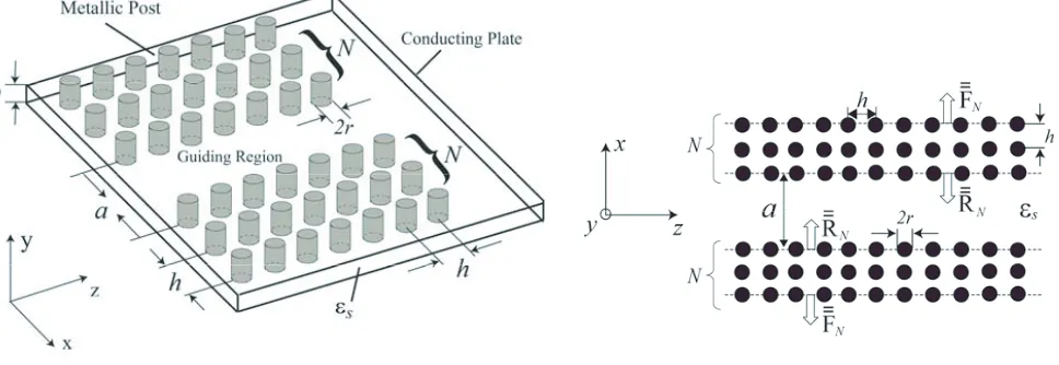
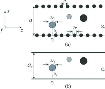
The post-wall waveguide, as illustrated in Fig. 1, is composed of periodic arrays of conducting circular posts (forming a planar lattice) embedded in a dielectric substrate that connect two parallel conducting plates. Fig. 1 shows the post-wall waveguide structure formed by N-layered square lattice. The electromagnetic fields are uniform in the y-direction (∂/∂y = 0), and the dominant mode T E10 is
excited. This periodic waveguide is similar to a two-dimensional photonic crystal waveguide formed by parallel circular rods, which are infinitely extended in they direction. The photonic crystal waveguide model is schematically depicted in Fig. 2.
Figure 1. Schematic of a post-wall waveguide bounded by N-layered post-walls in both sides.
Figure 2. Transversal view of a two-dimensional photonic crystal waveguide to modelN-layered post-wall waveguides.
Let us consider TE modes consisting of (Ey, Hx, Hz) fields. If we assume a longitudinal field
variation of eiβz, the two-dimensional guided wave propagating along the guiding region |x| ≤ a/2 is expressed as follows:
Ey(x, z) =U+(x, z)·c++U−(x, z)·c− (1)
with
U±(x, z) = {exp [(iκℓ(x∓a/2))] exp(iβℓz)δℓm} (2) c± = [c±ℓ ] (ℓ= 0,±1,±2, . . .) (3)
whereβℓ =β+ 2ℓπ/h, κℓ=
√
k2
s−βℓ2, ks=ω √ε
sµ0,εs is the permittivity of the dielectric substrate, β the propagation constant, and c± are the column vectors whose elements c+ℓ and c−ℓ represent the amplitudes of the transversally up-going and down-going ℓ-th Floquet modes. The amplitude vectors
c± satisfy the following relations:
c±=W(ω, β)R¯¯N(ω, β)·c∓ (4)
with
W(ω, β) = [exp(iκℓa)δℓm] (5)
element connects the reflected ℓ-th Floquet mode to the incident m-th Floquet mode. If the lattice constants, radii of circular rods, permittivity of dielectric substrate, and number of layers N of post
arrays are specified for a corresponding post-wall waveguide, the generalized reflection matrixR¯¯N(ω, β)
and transmission matrix F¯¯N(ω, β) can be calculated [10, 11] using the T-matrix of the single circular rod together with the lattice sums. From Eq. (4), we get the transcendental equation to determine the mode propagation constantβ as follows:
det [
I∓W(ω, β)R¯¯N(ω, β) ]
= 0 (6)
whereI is the unit matrix, and the signs∓stand for even(−) andodd(+) modes, respectively.
If only the fundamental Floquet mode with ℓ = 0 is propagating and all other diffraction orders are evanescent in the transverse direction, we can apply the so-called long wavelength approximation to Eq. (6). In this case, Eq. (6) is reduced to the following expression:
1∓exp(iκ0a) ¯R¯N00(ω, β) = 0. (7)
where ¯R¯N00(β, ω) denotes the (0,0) element ofR¯¯N(ω, β). As will be shown later, the reduced dispersion Equation (7) gives an excellent approximation to the full matrix Equation (6). The condition for the guided wave to be bounded by the layered post arrays shown in Fig. 2 is that all of the eigenvalues
λk(k= 1,2,3, . . .) of the transfer matrix over the unit cell in theydirection satisfy the relation|λk|<1
for the operating frequency range [10, 11]. This condition is always fulfilled when the operating frequency is located in the stopband of Bragg reflection in the transverse direction. Note that when the cylinders are composed of dielectrics, an enough number of layers of the periodic arrays is required to achieve the confinement of the wave field inside the guiding layer.
3. EQUIVALENT RECTANGULAR WAVEGUIDE
It is known [6] that when the transversal leakage of electromagnetic field through the gaps between the posts is sufficiently small, the post-wall waveguide modes practically coincide with theT Em0 modes of
an equivalent rectangular waveguide with an effective width ae = a+ ∆a. Let us now calculate the
effective width ae using the reduced dispersion Equation (7) for the evenmode. If the leakage is small
enough, the imaginary part of β due to the leakage loss can be regarded as a small perturbation. Such a treatment is allowed when ¯R¯N00(ω, β) satisfies the following condition:
R¯¯N
00(β, ω)≈1. (8)
In this case, Eq. (7) yields real β(ω) and κ0(ω) as unperturbed solutions. For the specified values of
β(ω) and κ0(ω), the width a of the original post-wall waveguide is changed to ae = a+ ∆a so as to
satisfy the relation:
exp [−iκ0(ω)(a+ ∆a)] =−1. (9)
Equation (9) means that the boundary condition for the perfect conductor is satisfied at x =±ae/2.
From Eq. (9) we have:
ae=π/κ0(ω). (10)
Althoughae slightly changes when ω varies, it may be practically regarded to be almost constant
within the same degree of approximation as in Eq. (8). Using the equivalent rectangular waveguide model, a very simple expression for the propagation constantβm(ω) of the evenT Em0 mode is retrieved
and given below:
βm(ω) =
√
k2
s−[(2m−1)π/ae]2 (m= 1,2,3, . . .). (11)
4. LEAKAGE LOSS AND ATTENUATION CONSTANT
by numerically solving Eq. (7). The decrement of |R¯¯N00(β, ω)| from unity is caused by the transverse leakage of the guided field. Let us introduce a small attenuation constant α of the guided wave due to the leakage and express the propagation constantβ as:
β =β0+iα (α≪β0). (12)
Under this condition, Eq. (7) for the fundamental mode is approximated as follows:
exp (−iκ0a) exp
(
−β0a
κ0
α
)
= ¯R¯N00(β0, ω) (13)
where κ0 =
√
k2
s−β02. Note that in Eq. (13) we have ignored the small perturbation to the real part
of β due to the deviation of |R¯¯N00(β0, ω)|from unity. As will be shown later, this approximation is well
justified by the fact that the difference between the real part of the propagation constantsβ calculated for N = 1 and for N =∞ without leakage losses is negligibly small. From Eq. (13), the attenuation constantα due to the leakage is given as follows:
α=−κ0
β0a
lnR¯¯N00(β0, ω). (14)
The attenuation constant α can also be calculated using a perturbation analysis taking into account the principle of power conservation. Due to leakage the guided waves carrying a total power
Pz =
∫a/2
0 Re{−EyHx∗}dx will attenuate as a function of z (‘*’ denotes the complex conjugate).
Assuming that the amplitudes of the fields decay exponentially with an attenuation constantα, and the carrier power Pz will show an exponential decay according to Pz ∼e−2αz. By the power conservation
principle, the decrease of Pz alongz direction should be equal to the transversal power dissipation per
unit length⟨Sx⟩= 21h∫0hRe{EyHz∗}dz. As a result, taking into account the orthogonality of the Floquet
modes, the attenuation constantα can be now expressed in the following form:
α= ⟨Sx⟩
Pz
= 0.5κ0F¯¯00N 2
×
κβ0 [sin(κ0a) +κ0a] +
M
∑
ℓ=−M
(ℓ̸=0)
βℓ γℓ
e−γℓa[sinh(γ
ℓa) +γℓa]R¯¯Nℓ0 2 −1 (15)
where γℓ =
√
β2
ℓ −ks2 denotes a propagation constant of the evanescent modes and M stands for the
truncation number of the modes. Equation (15) takes into account all interactions between the Floquet modes.
5. NUMERICAL RESULTS AND DISCUSSIONS
In order to confirm the validity of the long wavelength approximation to the dispersion equation, firstly we have calculated the propagation constantβ of the fundamentalT E10 mode by using the full matrix
Equation (6) and the reduced Equation (7), respectively, and compared both results. We assumed that the conductor loss in post-walls and the dielectric loss in the substrate are negligible. The first example encompasses a post-wall structure withεs/ε0 = 2.33,h= 2.0 mm, r= 0.4 mm and a= 7.2 mm [5, 6, 8].
Since h/r = 5.0 and h/a = 0.278, the gap width between two nearby posts is relatively small. The normalized propagation constants calculated from Eqs. (6) and (7) for different numbersN of layers of the post-walls are compared in Table 1. Note that the value of βh/2π calculated for Eq. (6) atN =∞ gives a rigorous value of the normalized propagation constant because the guided field is completely bounded for N = ∞ (note that from the practical point of view, it is enough to have about N = 5 layers along thex-axis in order to get the strong confinement of the modes in the guiding region). From Table 1, we can see that although the propagation constant calculated by Eq. (6) changes as the number
Table 1. Normalized propagation constants βh/2π of the fundamental T E10 mode for the N
-layered post-wall waveguide with εs/ε0 = 2.33, h = 2.0 mm, r = 0.4 mm and a = 7.2 mm.
The propagation constants obtained from the rigorous transcendental Equation (6) and the reduced dispersion Equation (7) are compared.
βh/2π
Eq. (6) Eq. (7)
f [GHz] N = 1 N = 2 N = 3 N =∞ N = 1 15.0 0.04330 0.04320 0.04320 0.04320 0.04330 20.0 0.14143 0.14140 0.14140 0.14140 0.14143 25.0 0.20811 0.20808 0.20808 0.20808 0.20829 30.0 0.26812 0.26810 0.26810 0.26810 0.26811
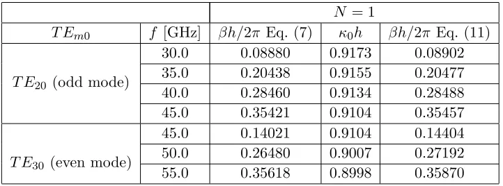
Table 2. Normalized propagation constantsβh/2πof the higher orderT E20andT E30modes calculated
by using Eq. (11) for the 1-layer post-wall waveguide with εs/ε0 = 2.33, h = 2.0 mm, r = 0.4 mm and
a= 7.2 mm.
N = 1
T Em0 f [GHz] βh/2π Eq. (7) κ0h βh/2π Eq. (11)
T E20 (odd mode)
30.0 0.08880 0.9173 0.08902 35.0 0.20438 0.9155 0.20477 40.0 0.28460 0.9134 0.28488 45.0 0.35421 0.9104 0.35457
T E30 (even mode)
45.0 0.14021 0.9104 0.14404 50.0 0.26480 0.9007 0.27192 55.0 0.35618 0.8998 0.35870
f = 20 GHz, 0.0144% at f = 25 GHz and 0.0075% at f = 30 GHz. It follows that if the gap between the nearby posts is small, the leakage of the guided wave through the gap becomes negligibly small and hence the guiding condition for T E10mode is well fulfilled even for N = 1.
Table 2 shows the comparison of the normalized propagation constants βh/2π of the calculated higher-order T E20and T E30 modes based on Eqs. (7) and (11). Other geometrical parameters are the
same as those in Table 1. The cutoff frequencies of the T E20 odd mode and the T E30 even mode are
28.77 GHz and 43.16 GHz, respectively. A very good agreement is observed over the wide frequency range.
Figure 3 demonstrates the dependence of the attenuation constant α versus the frequency in the range of 15 GHz–30 GHz. The dashed-dotted line and dashed line represent the attenuation constants based on Eqs. (14) and (15), respectively, which are then compared to the values shown in [6]. A good agreement is observed in the whole frequency range; however, it should be noted that the given attenuation constants α are slightly larger than those reported in [5, 6, 8]. Additionally, it should be mentioned that the data for the calculated attenuation constant based on Eq. (15) is closer to the reference data. This could be explained by the fact that Eq. (15) is a more general expression, since it takes into account all interactions between the Floquet modes.
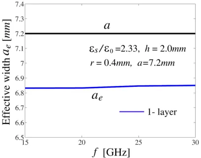
Figure 4 demonstrates the values of the effective widthae of the equivalent rectangular waveguide
calculated based on Eq. (10) for post-wall waveguide with εs/ε0 = 2.33, h = 2.0 mm, r = 0.4 mm,
a = 7.2 mm, and N = 1. We can see that the effective width ae is slightly smaller than the physical
distance abetween two post-walls and increases in proportion to the operating frequency f. Although the effective width ae slightly changes depending on the frequency, its variation is very small and less
Figure 3. Attenuation constant α calculated using (14) and (15) plotted by the dashed-dotted line and dashed line, respectively, is compared with Ref. [6] represented by the solid line.
Figure 4. Effective width ae of the equivalent
rectangular waveguide calculated using (10) versus frequency for εs/ε0 = 2.33, h = 2.0 mm,
r= 0.4 mm, a= 7.2 mm, andN = 1.
Figure 5. Effective width ae of the equivalent
rectangular waveguide calculated using (10) versus frequency for εs/ε0 = 2.2, h = 5.165 mm,
r = 0.3875 mm, a= 11.759 mm, and N = 1 (blue line) andN = 2 (red line).
parameter, we can employ a value for ae that is averaged over the operating frequency range. The
post-wall waveguide filters will be analyzed later in this section by using the averaged value of ae as a
fixed effective width over the operating bandwidth.
The second example includes a structure with εs/ε0 = 2.2, h = 5.165 mm, r = 0.3875 mm, and
a= 11.759 mm after [6]. Since h/r = 13.329 and h/a= 0.439, the gap width is much larger than that of the first example. Table 3 shows the comparison of the normalized propagation constants calculated from Eqs. (6) and (7) for different numbers of layersN of the post-walls. We can see that the propagation constant calculated by the reduced dispersion Equation (7) forN = 1 is not in excellent agreement with that calculated by Equation (6) for N = ∞. Particularly, the relative error for N=1 is: 4.3806% at
Table 3. Normalized propagation constants βh/2π of the fundamental T E10 mode for the N
-layered post-wall waveguide with εs/ε0 = 2.2, h = 5.165 mm, r = 0.3875 mm, and a = 11.759 mm.
The propagation constants obtained from the rigorous transcendental Equation (6) and the reduced dispersion Equation (7) are compared.
βh/2π
Eq. (6) Eq. (7)
f [GHz] N = 1 N = 2 N = 3 N =∞ N = 1 8.0 0.04152 0.04056 0.04056 0.04060 0.04246 10.0 0.15980 0.15956 0.15956 0.15956 0.15998 12.0 0.23368 0.23352 0.23352 0.23353 0.23394 14.0 0.29844 0.29836 0.29836 0.29853 0.29878
(c) (a)
(b)
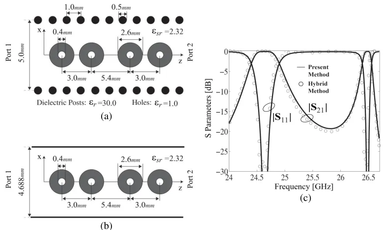
Figure 6. Bandpass filter with three circular posts of conductor: (a) Original post-wall waveguide structure; (b) Equivalent rectangular waveguide structure, and (c)S-parameters of the circuit (a).
effective widthaedoes not change significantly even if the number of post-wall layers is increased. It is
worth emphasizing that for the present structure with a wider gap ash/r= 13.329, the effective width
ae becomes larger than the physical width a of the post-wall waveguide. As the gap width increases,
the rate of leakage of guided wave increases. This situation is quite different from that of a narrow gap case discussed in the first example.
Finally, we shall analyze two post-wall waveguide bandpass filters by using the method of images (Appendix A). The interested readers may refer to [15]. When a post-wall waveguide structure is specified, firstly we calculate its effective widthaeby using Eq. (10) and define an equivalent rectangular
waveguide. We calculated the scattering parameters in the rectangular waveguide by using the image theory and the two-dimensional photonic-crystal model. Two numerical examples for ultra-compact bandpass filter by using the boundary integral-resonant mode expansion (BI-RME) method [7] and a hybrid method [9] are shown in Figs. 6 and 7. The S-parameters calculated by the proposed method are compared with those in [7, 9]. We observe that all of the S-parameters obtained by the present method are in excellent agreement with those reported in [7, 9]. For the structure shown in Fig. 6(a), the material loss was ignored in our analysis, but a conductor loss of σc= 4×10⁷S/m and a dielectric
loss of σd = 0.001 S/m were considered in [7]. The small difference in the S-parameters observed in
(c) (a)
(b)
Figure 7. Dual-band bandpass filter with four concentric circular posts of dielectric with air-hole: (a) Original post-wall waveguide structure; (b) Equivalent rectangular waveguide structure, and (c)
S-parameters of the circuit (a).
6. CONCLUSION
In the manuscript, we have reported a novel semi-analytical approach for analyzing post-wall waveguides and circuits based on the model of two-dimensional photonic crystals. The generalized reflection matrix is used to derive the dispersion equation for T Em0 modes. Solving this dispersion equation based on
a perturbation analysis, the attenuation constant (due to the leakage loss) and the effective width of the equivalent rectangular waveguide are calculated. To validate the proposed formalism, numerical examples for post-wall waveguides and post-wall waveguide-based passive circuit, such as bandpass filter, are presented and compared to other references yielding a perfect agreement between the S -parameters over a wide frequency range. It is important to mention that the proposed semi-analytical formulation is not time-consuming, which could be considered as a major advantage of the proposed formulation. The desktop CPU runtime on the 3.6 GHz Intel Core i7 with 8 GB RAM per one frequency is around 0.2 second. The authors believe that the proposed method is a very apt tool for designing advanced multi-functional, ultra-compact submillimeter passive circuit devices. It is expected to give an insight into the physics underlying the proper guiding mechanism in such periodic waveguide structures and/or bandgap (meta) materials.
ACKNOWLEDGMENT
V. Jandieri acknowledges financial support from the Alexander von Humboldt Foundation. The work is supported by Shota Rustaveli National Science Foundation (SRNSF) (Grant No. 216662 and Grant No. FR/25/6-100/14) The work is also supported by JSPS KAKENHI (Grant No. 24560430). D. Erni acknowledges the support from the DFG SFB/TRR 196 MARIE.
APPENDIX A.
(a)
(b)
Figure A1. Top view of circular posts inserted into (a) a post-wall waveguide and into (b) equivalent rectangular waveguide with the effective width ae.
in Section 3, the original structure is replaced by the equivalent rectangular waveguide structure shown in Fig. A1(b). In this section, we briefly present an accurate and rigorous approach for analyzing the scattering properties of the vertical posts and relevant electromagnetic bandgap structures in such a rectangular waveguide. The interested readers may be referred to [15].
Let us consider thei-th post with radiusrj whose center is located at (∆j, zj) within the equivalent
rectangular waveguide. The excitation is assumed to be inT Em0 mode. The excitation in the forward
direction is expanded into the cylindrical waves as following:
Ey,mi =a+msin(κmx) exp(iβmz) = ΦT1 ·p+m·a+m (A1)
with
Φ1 =
[
Jn(ksρ+0) exp(inϕ + 0)
]
(A2)
p+m = [p+mn], p+mn= [
1 2(−i)
n−1{exp [i(nθ
m−κm∆j)]−(−1)nexp[−i(nθm−κm∆j)]}
] (A3)
cosθm = κm
ks
, ρ+0 = √
(x−∆j)2+ (z−zj)2, cosϕ+0 =
x−∆j
ρ+0 (A4)
whereκm = mπa (m= 1,2. . .),βmis the propagation constant of them-th mode,a+mlabels the amplitude
of the incident field,Jnthen-th order Bessel function, and (ρ+0, ϕ+0) the polar coordinates with the origin
at the center of the post. Taking into account an infinite number of mirror images of the post with respect to the side walls, the scattered field is expressed as:
Eys= ∞ ∑
ℓ=−∞
∞ ∑
n=−∞
XnHn(1)(ksρ+ℓ ) exp(inϕ
+ ℓ)− ∞ ∑ ℓ=−∞ ∞ ∑ ℓ=−∞
(−1)nXnHn(1)(ksρ−ℓ) exp(−inϕ
+
ℓ) (A5)
with
ρ±ℓ = √
(xℓ∓∆j)2+ (z−zj)2, cosϕ±ℓ =
xℓ∓∆j
ρ±ℓ (A6)
where xℓ = x −2aℓ, Hn(1) is the n-th order Hankel function of the first kind. Xn are unknown
amplitudes of the scattered multipole fields, and (ρ±ℓ , ϕ±ℓ) are the local polar coordinates with the origins at (2aℓ±∆j, zj). The array has a period of 2aand contains two cylinders within its unit cell.
the unknown scattering amplitudes Xn are expressed in a closed form through the lattice sums, the
translation matrices of cylindrical waves and the T-matrix of the circular cylinder in isolation. Next, using a Fourier integral representation of the Hankel functions, the multipole fields are transformed into a series of space harmonics of plane waves, and the reflection and transmission matrices of the posts for the incidentT Em0 mode are derived. Finally, a recurrence formula is applied to obtain the generalized
reflection and transmission matrices characterizing the layered structure.
REFERENCES
1. Hirokawa, J. and M. Ando, “Single-layer feed waveguide consisting of posts for plane TEM wave Excitation in parallel plates,”IEEE Trans. Antennas Propagat., Vol. 46, No. 5, 625–630, 1998. 2. Uchiyama, H., T. Takenoshita, and M. Fujii, “Development of a “laminated waveguide”,” IEEE
Trans. Microwave Theory Tech., Vol. 46, No. 12, 2438–2443, 1998.
3. Entesari, K., A. P. Saghati, V. Sekar, and M. Armendariz, “Tunable SIW structures,” IEEE Microwave Magazine, 34–54, June 2015.
4. Yan, L., W. Hong, K. Wu, and T. J. Cui, “Investigations on the propagation characteristics of the substrate integrated waveguide based on the method of lines,” IEE Proc. — Microw. Antennas Propag., Vol. 152, No. 1, 35–42, 2005.
5. Xu, F. and K. Wu, “Guided-wave and leakage characteristics of substrate integrated waveguide,”
IEEE Trans. Microwave Theory Tech., Vol. 53, No. 1, 66–73, 2005.
6. Deslandes, D. and K. Wu, “Accurate modeling, wave mechanisms, and design considerations of a substrate integrated waveguide,”IEEE Trans. Microwave Theory Tech., Vol. 54, No. 6, 2516–2526, 2006.
7. Bozzi, M., F. Xu, L. Perregrini, and K. Wu, “Circuit modeling and physical interpretation of substrate integrated waveguide structures for millimeter-wave applications,” Int. J. Microwave Opt. Technol., Vol. 3, No. 3, 329–338, 2008.
8. Kishihara, M., I. Ohta, K. Okubo, and J. Yamakita, “Analysis of post-wall waveguide based on
H-plane planar circuit approach,”IEICE Trans. Electronics, Vol. E92-C, No. 1, 63–71, 2009. 9. Wu, X. H. and A. A. Kishk, “Hybrid of method of moments and cylindrical eigenfunction expansion
to study substrate integrated waveguide circuits,”IEEE Trans. Microwave Theory Tech., Vol. 56, No. 10, 2270–2276, 2008.
10. Yasumoto, K., H. Toyama, and T. Kushta, “Accurate analysis of two-dimensional electromagnetic scattering from multilayered periodic arrays of circular cylinders using lattice sums technique,”
IEEE Trans. Antennas Propagat., Vol. 52, No. 10, 2603–2611, 2004.
11. Yasumoto, K., Electromagnetic Theory and Applications for Photonic Crystals, Chapter 3, CRC Press, 2005.
12. Yasumoto, K., H. Jia, and K. Sun, “Rigorous modal analysis of two-dimensional photonic crystal waveguides,”Radio Sci., Vol. 40, No. 6, RS6S02, 2005.
13. Jandieri, V., K. Yasumoto, and J. Pistora, “Coupled-mode analysis of contra-directional coupling between two asymmetric photonic crystals waveguides,”Journal of the Optical Society of America A, Vol. 31, No. 3, 518–523, 2014.
14. Yasumoto, K., H. Maeda, and V. Jandieri, “Analysis of post-wall waveguides using a model of two-dimensional photonic crystal waveguides,” Proceedings of the IEEE International Conference on Signal Processing and Communication (ICSC-2015), 74–79, Noida, India, April 2015.