Design and Heat Transfer Performance of Shell and Tube Heat
Exchanger by Using Nano Fluids
1]
Dr. Ashok Kumar Vootla,
[2]Syed Mukasirsha
Associate professor, Dept. Mechanical engineering mother Theressa College of engg & tech.
Peddapalli, , india
Dept of Mechanical engineering mother Theressa College of engg & tech. Peddapalli, , india
E-Mail: [email protected] , [email protected]
Abstract: Heat exchanger is a device used to transfer heat between one or more fluids. In this thesis, different nano fluids mixed with base fluid water are analyzed for their performance in the radiator. The nano fluids are Aluminum Oxide, Silicon Oxide and Titanium carbide for two volume fractions 0.7, 0.8. Theoretical calculations are done determine the properties for nano fluids and those properties are used as inputs for analysis.3D model of the shell and tube heat exchanger is done in Pro/Engineer. CFD analysis is done on the shell and tube heat exchanger for all nano fluids and volume fraction and thermal analysis is done in Ansys for two materials Aluminum and Copper for better fluid at better volume fraction from CFD analysis.
Key words: Finite element analysis, steam boiler, CFD analysis, thermal analysis.
I. INTRODUCTION
Heat exchangers are one of the mostly used equipment in the process industries. Heat Exchangers are used to transfer heat between two process streams. One can realize their usage that any process which involve cooling, heating, condensation, boiling or evaporation will require a heat exchanger for these purpose.
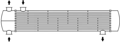
Fig. Segmental baffled one-pass shell and two-pass
tube shell-and-tube heat exchanger
Different heat exchangers are named according to their application. For example, heat exchangers being used to condense are known as condensers, similarly heat exchanger for boiling purposes are called boilers. Performance and efficiency of heat
transfer using least area of heat transfer and pressure drop. A better presentation of its efficiency is done by calculating over all heat transfer coefficient. Pressure drop and area required for a certain amount of heat transfer, provides an insight about the capital cost and power requirements (Running cost) of a heat exchanger. Usually, there is lots of literature and theories to design a heat exchanger according to the requirements.
II. LITERATURE REVIEW
Shell-and-tube heat exchangers are used widely in the chemical process industries, especially in refineries, because of the numerous advantages they offer over other types of heat exchangers. A lot of information is available regarding their design and construction. The present notes are intended only to serve as a brief introduction.
III. RESEARCH GAP & PROBLEM DESCRIPTION
In the research by R. Shankar Subramanian, the
shell and tube heat exchanger is taken in the water
with various temperatures. In this thesis, along with
carbide nano fluid at different volume fractions (0.7
and 0.8 ) of the shell and tube heat exchanger is
analyzed for heat transfer properties, temperature,
pressure ,velocity and mass flow rates in CFD
analysis. In thermal analysis, two materials Copper
and Aluminum are considered for heat exchanger.
Modeling is done in Pro/Engineer, Thermal analysis
and CFD analysis is done in Ansys. The boundary
conditions for thermal analysis are temperatures, for
CFD analysis is pressure, velocity and temperature.
IV . INTRODUCTION TO CAD/CAE:
Computer-aided design (CAD), also known as
computer-aided design and drafting (CADD), is the use of computer technology for the process of design and design-documentation.
INTRODUCTION TO PRO-ENGINEER
Pro/ENGINEER Wildfire is the standard in 3D product design, featuring industry-leading productivity tools that promote best practices in design while ensuring compliance with your industry and company standards. Integrated Pro/ENGINEER CAD/CAM/CAE solutions allow you to design faster than ever, while maximizing innovation and quality to ultimately create exceptional products.
Different modules in pro/engineer
Part design, Assembly, Drawing& Sheet metal.
INTRODUCTION TO FINITE ELEMENT
METHOD:
Finite Element Method (FEM) is also called as Finite Element Analysis (FEA). Finite Element Method is a basic analysis technique for resolving and substituting complicated problems by simpler ones, obtaining approximate solutions Finite element method being a flexible tool is used in various industries to solve several practical engineering problems. In finite element method it is feasible to generate the relative results.
V.MODELING AND ANALYSIS
3D MODEL OF SHELL AND TUBE HEAT
EXCHANGER
CUT SECTION
2D MODEL OF SHELL AND TUBE HEAT
CALCULATIONS TO DETERMINE
PROPERTIES OF NANO FLUID BY
CHANGING VOLUME FRACTIONS
Volume fraction= 0.7 & 0.8(taken from journal
paper)
NOMENCLATURE
ρnf = Density of nano fluid (kg/m3)
ρs = Density of solid material (kg/m3)
ρw = Density of fluid material (water) (kg/m3)
ϕ = Volume fraction
Cpw = Specific heat of fluid material (water) (j/kg-k)
Cps = Specific heat of solid material (j/kg-k)
µw = Viscosity of fluid (water) (kg/m-s)
µnf = Viscosity of Nano fluid
(kg/m-s)
Kw = Thermal conductivity of fluid material (water)
(W/m-k)
Ks = Thermal conductivity of solid material
(W/m-k)
NANO FLUID CALCULATIONS
DENSITY OF NANO FLUID
ρnf = ϕ×ρs + [(1-ϕ) × ρw]
SPECIFIC HEAT OF NANO FLUID
Cp nf =
ϕ ρ ( ϕ)(ρ ) ϕ ρ ( ϕ) ρ
VISCOSITY OF NANO FLUID
µnf =µw (1+2.5ϕ)
THERMAL CONDUCTIVITY OF NANO FLUID
Knf =
( )( ) ϕ ( )( ) ϕ × kw
NANO FLUID PROPERTIES
CFD ANALYSIS OF SHELL AND TUBE HEAT
EXCHANGER
ALUMINUM OXIDE NANO FLUID
VOLUME FRACTION - 0.7
STATIC TEMPERATURE
VELOCITY MAGNITUDE
HEAT TRANSFER CO-EFFICIENT
Total Heat Transfer Rate (w)
SILICON OXIDE NANO FLUID
VOLUME FRACTION - 0.7
STATIC TEMPERATURE
VELOCITY MAGNITUDE
HEAT TRANSFER CO-EFFICIENT
TITANIUM CARBIDE NANO FLUID
VOLUME FRACTION - 0.7
STATIC PRESSURE
STATIC TEMPERATURE
HEAT TRANSFER CO-EFFICIENT
REPORTS
6. RESULTS AND DISCUSSIONS THERMAL ANALYSIS OF SHELL AND TUBE
HEAT EXCHANGER
MATERIAL-ALUMINUM ALLOY
ALUMINUM OXIDE NANO FLUID AT
VOLUME FRACTION - 0.7
MATERIAL-COPPER ALLOY
TEMPERATURE
GRAPHS
CFD analysis Graphs
THERMAL ANALYSIS GRAPHS
0.00E+00 5.00E+02 1.00E+03 1.50E+03 al 0.7 al 0.8 si 0.7 si 0.8 tic 0.7 tic 0.8
pressure
pressure 2.6 2.8 3 3.2 3.4 al 0.7 al 0.8si 0.7si 0.8ti 0.7ti 0.8
velocity
velocity 0 50000 100000 150000 al 0.7 al 0.8 si 0.7 si 0.8 ti 0.7 ti 0.8Heat transfer coefficient
Heat transfer coefficient 0 500 1000
al 0.7 al 0.8 si 0.7 si 0.8 ti 0.7 ti 0.8
mass flow rate
m as s f… 0 50000000 100000000 150000000 200000000 al 0.7 al 0.8 si 0.7 si 0.8 tic 0.7 tic 0.8
heat transfer rate
7. CONCLUSION
3D model of the shell and tube heat exchanger is done in Pro/Engineer. CFD analysis is done on the shell and tube heat exchanger for all nano fluids Aluminum Oxide, Silicon Oxide and Titanium Carbide and at different volume fractions 0.7, 0.8. By observing the CFD analysis results, the pressure are more for aluminum oxide at volume fraction of 0.7 and mass flow rate is more for titanium carbide at volume fraction of 0.8. The heat transfer coefficient and heat transfer rate are s more for Aluminum oxide at volume fraction of 0.8. Thermal analysis is done for two materials Aluminum and Copper taking heat transfer coefficient value of Aluminum oxide at 0.8 volume fractions from CFD analysis. By observing thermal analysis results, heat flux is more when Copper is used than Aluminum alloy.
REFERENCES
1. A.O. Adelaja, S. J. Ojolo and M. G. Sobamowo,
“Computer Aided Analysis of Thermal and
Mechanical Design of Shell and Tube Heat
Exchangers”, Advanced Materials Vol. 367 (2012)
pp 731
-737 © (2012) Trans Tech Publications, Switzerland.
2. Yusuf Ali Kara, Ozbilen Guraras, “A computer
program for designing of Shell and tube heat
exchanger”, Applied Thermal Engineering 24(2004)
1797–1805
3. Rajagapal THUNDIL KARUPPA RAJ and
Srikanth GANNE, “Shell side numericalanalysis of a
shell and tube heat exchanger considering the effects
of baffle inclination angle on fluid flow”, Thundil
Karuppa Raj, R., et al: Shell Side Numerical Analysis
of a Shell and Tube Heat Exchanger ,THERMAL
SCIENCE: Year 2012, Vol. 16, No. 4, pp.
1165-1174.
4. S. Noie Baghban, M. Moghiman and E. Salehi, “
Thermal analysis of shell-side flow of shell-and tube
heat exchanger using experimental and theoretical
methods” (Received: October 1, 1998 -Accepted in
Revised Form: June 3, 1999).
5. A.GopiChand, Prof.A.V.N.L.Sharma , G.Vijay
Kumar, A.Srividya, “Thermal analysis of shell and
tube heat exchanger using mat lab and floefd
software”,Volume: 1 Issue: 3 276 –281,ISSN: 2319 –
1163.
6. Hari Haran, Ravindra Reddy and Sreehari,
“Thermal Analysis of Shell and Tube Heat ExChanger Using C and Ansys” ,International
Journal of Computer Trends and Technology (IJCTT)
–volume 4 Issue 7–July 2013.
7. Donald Q.Kern. 1965. Process Heat transfer
(23rdprinting 1986). McGraw-Hill companies.ISBN
0-07-Y85353-3.