A Subarray Design Method for Low Sidelobe Levels
Kai Yang*, Yuqiang Wang, and Hai Tang
Abstract—Partitioning large arrays into subarrays can reduce system cost. In this paper, we use identical subarrays to partition a large rectangular aperture. The periodical structure in a large array is broken down by changing the orientations of the subarrays. In each subarray, the element positions are optimized by particle swarm optimization (PSO) to obtain low sidelobe levels. In order to reduce the coupling among the elements, the minimum element distance measured in Euclidean space is restricted in the procedure of optimization. And a modified PSO is proposed to solve the optimization problem with this constraint. Better results can be obtained than the element distance constraint measured in Chebyshev space. This simple but efficient subarray design method is demonstrated through several numerical simulations.
1. INTRODUCTION
Large antenna arrays are becoming increasingly important in real-world applications due to their high resolution and high power. More antennas usually mean a higher cost of array control devices. Partitioning a large array into a number of subarrays is a common technique which reduces the cost. The subarray technique is a nice tradeoff between the cost and array performance. To avoid grating lobes, the subarrays should be designed carefully to avoid periodic structures. One practical method to eliminate the grating lobes is to design overlapped subarrays using Butler matrix or lens feeds [1], but it is relatively difficult and costly to build. Other approaches attempt to break the periodicity by using random subarrays [2], utilizing rotational symmetry [3], applying a hybrid genetic algorithm to optimize the subarray size and subarray weights to disrupt the periodic quantization, and others [4]. However, this method is only suitable for linear arrays. Furthermore, many different subarray sizes are much more costly to build.
Using irregular-shaped subarrays is a popular choice to avoid grating lobes [5, 6]. With the consideration of system cost, usually only one or two types of subarrays are used to partition an aperture, such as L-octomino shaped subarrays and polyhex-shaped subarrays. However, solving the exact partition and quasi-exact partition is a time-consuming problem. Sometimes it is impractical to exactly partition an aperture with given-shaped subarrays [7], especially for a widely used aperture, such as rectangular aperture. It is easy to partition a rectangular aperture with congruent small rectangular subarrays. Actually, simply bisecting each square and altering the orientations of each square can prevent periodicity. This means that if the rectangular subarray is non-symmetry, we can partition an aperture with this subarray by altering the orientations. This is the idea of this communication to partition a large array and break its periodicity.
Sparse antenna arrays can reduce the number of elements and improve the array performance. Compared with uniform arrays, sparse arrays have more degrees of freedom by optimizing the element positions. Many optimization methods, such as genetic algorithm [8, 9], simulated annealing [10], particle swarm optimization (PSO) [11, 12], ADS-based algorithm [13], iterative linear programming [14], Taguchi method [15, 16], and teaching learning method [17], have been presented for sparse array design.
Received 3 November 2019, Accepted 23 December 2019, Scheduled 14 January 2020
* Corresponding author: Kai Yang ([email protected]).
In sparse array design with randomly spaced elements, usually the minimum element distance should be restricted due to the mutual coupling effect. In order to limit the adjacent element distance in planar arrays, [8] relaxes the restriction on element distance from the actual distance to Chebyshev distance. However, this reduces the degrees of freedom and will degrade the array performance.
In this paper, we propose a subarray design method for low sidelobe levels, which has advantages of ease in design and low sidelobe levels. The array is composed of rectangle-shaped subarrays with different orientations. In the subarray, the element positions are optimized by a modified PSO to ensure the adjacent element distance to be greater than a given value. Then the amplitude weights of the subarrays are optimized to further improve the performance.
2. THE PROPOSED IDEA
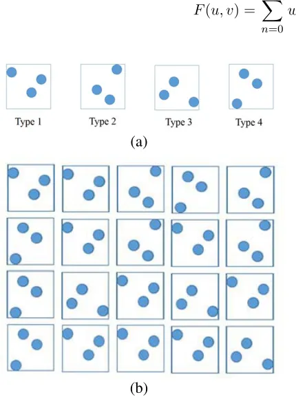
Figure 1 shows an aperiodic planar array by using one type of rectangular-subarrays with different orientations. The premise of this type of array is that any subarray is neither bilaterally symmetrical nor centrally symmetrical. As an example, four types of subarrays by the polyforms are shown in Figure 1(a). Here, type ‘2’ is obtained by rotating type “1” 90 degrees clockwise about the center. Therefore, the orientations of the subarrays in Figure 1(b) can be represented as [‘1’ ‘1’ ‘2’ ‘4’ ‘2’; ‘4’ ‘1’ ‘2’ ‘1’ ‘2’; ‘4’ ‘3’ ‘1’ ‘3’ ‘1’; ‘4’ ‘1’ ‘1’ ‘1’ ‘3’]. This type of array is able to cover an aperture in such a way to not give rise to any periodic structure along any direction. We can optimize the element positions to ensure this premise satisfied and improve the array performance. In the following, we will apply the PSO to optimize the element positions, subarray weights, and subarray orientations to minimize the sidelobe levels.
Consider an N-element planar subarray located in the xoy plane as shown in Figure 2. The array factor of this subarray is given by
F(u, v) =
N−1
n=0
wnexp[j2π(xnu+ynv)] (1)
(a)
(b)
Figure 1. An example of array composed by four types of subarrays. (a) Those four types of subarrays are obtained by rotating a subarray type “1”. (b) An example of array.
X
Y Z
the nth element (xn,yn,0)
O
Nth element (xN,yN,0)
θ
φ
whereu= sin(θ) cos(φ), v= sin(θ) sin(φ), (xn,yn), andwn are the position of thenth element and its excitation, respectively. θ is the elevation as the angle down from the z-axis. φ is the azimuth angle measured counterclockwise from thex-axis in thexoy plane. Here, in the same subarray, the excitations of different elements are the same. They may be different for different subarrays. To avoid significant mutual coupling in an array environment, the element distance of any pair of elements{n1, n2} should be equal to or greater thandc,
(xn1 −xn2)2+ (yn
1−yn2)2 ≥dc (2)
This constraint of minimum element distance is a nonlinear constraint which cannot be easily optimized by stochastic algorithms (such as GA and PSO). To simplify the problem, in [8], the element distance constraint in Eq. (2) is loosened as
max (|xn1 −xn2|,|yn1−yn2|)≥dc (3)
It is easy to prove that the constraint (2) is met when the constraint (3) of the element distance measured in Chebyshev space is met. However, this loosened constraint decreases the degrees of freedom. We will propose a modified PSO algorithm to optimize the element positions with the constraint (2).
PSO is a popular stochastic, population-based algorithm consisting of independent particles with social interactions. Each particle has its own position p and velocity v. The iterative steps of this algorithm are described as
vtk = avkt−1+c1rand·
pt, bestk −ptk
+c2rand·gt−ptk (4)
ptk+1 = ptk+vtk (5)
where superscripttrefers to thetth iteration time, and subscriptk refers to thekth particle. Here, the particle position represents the element position,p= [x1, x2, ..., xN, y1, ..., yN].
To satisfy the constraint (2), first we need to initialize the particle positions to satisfy this constraint. However, according to Eq. (5), we cannot guarantee thatptk+1 meets the constraint (2) whenptk meets this constraint. Therefore, a modification of PSO should be made.
In PSO, each individual in the swarm accelerates toward the personal best and global best positions which have been ever found. When the particles roam outside the solution space, the velocity will be adjusted. There are three different boundary conditions as given in [18]. However, in this paper, we suppose that the boundary is randomly weighted reflecting walls. When a particle hits the boundary in one of the dimensions, the sign of the velocity in that dimension is changed, and the absolute value is randomly decreased. This is a hybrid of absorbing wall and reflecting wall which can increase the randomness and coverage to the global optimum faster. The essential steps of adjusting the velocities are described as
1) For the array layout corresponding to the kth particle, we calculate the element distances and find those elements if their distances to any other elements in the array are less than dc. Here the index of those elements are noted as: m1,m2, ..., mg.
2) Adjust the velocity as
vk(mi) =−αvk(mi);
vk(mi+N) =−αvk(mi+N); i= 1, ..., g. (6)
whereα is a parameter in the set (0, 1).
3) With the new velocity, iterate steps 1) and 2) until all the element distances are no less than dc, or the maximum iteration numberT is arrived at. If the element distance of any pair of antennas is less than dc afterT iteration times, initialize pk and make vk= 0.
3. SIMULATION RESULTS
3.1. Euclidean Distance Versus Chebyshev Distance
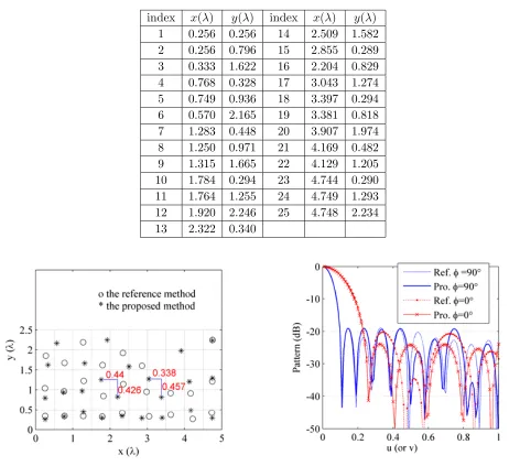
Firstly, the modified PSO method will be compared with a genetic algorithm [8]. [8] employed a modified genetic algorithm to synthesize a sparse planar array with a constraint of minimum element Chebyshev distance. A 100-element planar symmetry sparse array with an aperture of 9.5λ×4.5λ was obtained. The optimization objective was to minimize the summation of peak sidelobe levels along φ = 0◦ and φ= 90◦ with all the excitations being ones. We apply the proposed method to optimize this problem. Instead of the Chebyshev distance used in [8], the element Euclidean distance is restricted to be greater than 0.5λ. The mainlobe width is set to be the same as in [8]. In PSO, the population includes 50 individuals. The maximum iteration number is set as 600. After 5 independent simulations, the average fitness value is equal to −40.2 dB, and the best one is −42.96 dB (the elements positions are given in Table 1).
Table 1. The element positions optimized by the proposed method.
index x(λ) y(λ) index x(λ) y(λ)
1 0.256 0.256 14 2.509 1.582
2 0.256 0.796 15 2.855 0.289
3 0.333 1.622 16 2.204 0.829
4 0.768 0.328 17 3.043 1.274
5 0.749 0.936 18 3.397 0.294
6 0.570 2.165 19 3.381 0.818
7 1.283 0.448 20 3.907 1.974
8 1.250 0.971 21 4.169 0.482
9 1.315 1.665 22 4.129 1.205
10 1.784 0.294 23 4.744 0.290
11 1.764 1.255 24 4.749 1.293
12 1.920 2.246 25 4.748 2.234
13 2.322 0.340
Figure 3. Comparison of array layouts of [8] and the proposed method.
Figure 3 shows the array configuration of the optimized array. It can be found that the Chebyshev distances between some elements are smaller than 0.5λ, for example, the distance between the 11th element and 16th element (In Table 1). But the Euclidean distances are always greater than 0.5λ. Compared with the method in [8], the proposed method has more degrees of freedom, so that better results can be achieved.
Figure 4 shows the pattern inφ= 0◦ andφ= 90◦. The sidelobe level alongφ= 0◦ of the proposed method is 3.7 dB lower than that of [8] with the same mainlobe width. And the sidelobe levels along φ= 90◦ of both methods are almost the same. Meanwhile, the directivity of the proposed method is 0.1 dB higher than the reference method.
3.2. Large Array Design Consisting of Subarrays
The goal of this subsection is to design a planar array to cover a 20λ×20λ aperture. 36 subarrays are used to partition this aperture. All the subarrays are the same: 2.9λ×2.9λsubarray. The center to center space of adjacent subarrays is 3.4λ. In each subarray, there are N = 21 identical antenna elements.
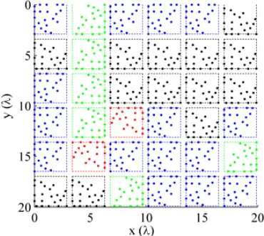
Orientations of the subarrays and positions of the elements in the subarray are optimized. The minimum element distance is set to 0.5λ. The objective is to minimize the peak sidelobe level. The modified PSO is applied to solve this problem. The optimized array is shown in Figure 5. The orientations of the subarrays can be represented as [‘4’ ‘2’ ‘4’ ‘4’ ‘4’ ‘3’; ‘3’ ‘2’ ‘3’ ‘3’ ‘3’ ‘3’; ‘4’ ‘2’ ‘3’ ‘3’ ‘3’ ‘3’; ‘4’ ‘2’ ‘1’ ‘4’ ‘3’ ‘4’; ‘4’ ’1’ ‘4’ ‘4’ ‘4’ ‘2’; ‘3’ ‘3’ ‘2’ ‘4’ ‘4’ ‘4’]. The peak sidelobe level of this array is−15.5 dB. Its array pattern is given in Figure 6.
Figure 5. Array layout of the sparse array whose element positions and subarray orientations are optimized.
Figure 6. The pattern of the array in Figure 5.
For comparison, suppose that the orientations of all subarrays are the same. In each subarray, the 21 elements are uniformly distributed in the 2.9λ×2.9λaperture, i.e., a 5×5 elements array with the four elements on vertices being deleted. Because the distance between two adjacent subarrays is greater than 1λ, and the subarray is a uniform array with element spacing greater than 0.5λ, grating lobes appear. The peak sidelobe level of this array is −0.02 dB, which is much higher than that of the array in Figure 5. Then the element positions in the subarray are optimized, and the subarrays keep the same orientations. The peak sidelobe level of the optimized array is −12.4 dB which is still higher than that of the array whose element positions and subarray orientations are optimized simultaneously. This improvement is benefited from optimization of orientations.
Figure 7. Array pattern of the sparse array whose element positions, subarray orientations and amplitude weightings are optimized by the proposed method.
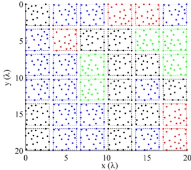
Figure 8. The array layout corresponding to Figure 7.
Figure 9. The amplitude weighting of subarrays corresponding to Figure 8.
value equal to or less than 10. The modified PSO is applied to solve this problem. After 5 independent runs, the lowest peak sidelobe level obtained is equal to −23.7 dB (Figure 7) which is 8 dB lower than that of the array whose element positions and subarray orientations are optimized. The optimized array layout is given in Figure 8, and the amplitude weighting at the subarray ports is shown in Figure 9.
It is also worth noting that the subarray positions can also be optimized to obtain a better result, and of course this will increase the degree of freedom which makes it more difficult to find the global optimum.
4. CONCLUSION
ACKNOWLEDGMENT
This work was supported in part by Shanghai Municipal Science and Technology major Project under Grants No. 2018SHZDZX04 and the National Natural Science Foundation of China under Grants 91638205.
REFERENCES
1. Mailloux, R. J., Phased Array Antenna Handbook, Artech House, Boston, MA, 2005.
2. Wang, H., D. G. Fang, and Y. L. Chow, “Grating lobe reduction in a phased array of limited scanning,”IEEE Trans. Antennas Propag., Vol. 55, 1581–1586, Jun. 2008.
3. Gregory, M. D., F. A. Namin, and D. H. Werner, “Exploiting rotational symmetry for the design of ultra-wideband planar phased array layouts,”IEEE Trans. Antennas Propag., Vol. 61, 176–184, Jan. 2013.
4. Haupt, R. L., “Optimized weighting of uniform subarrays of unequal sizes,” IEEE Trans. Antennas Propag., Vol. 53, 1207–1210, Apr. 2007.
5. Mailloux, R. J., S. G. Santarelli, and T. M. Roberts, “Wideband arrays using irregular (polyomino) shaped subarrays,” Electronics Letters, Vol. 42, No. 18, 1019–1020, 2006.
6. Isernia, T., M. D’Urso, and O. Bucci, “A simple idea for an effective sub-arraying of large planar source,” IEEE Antennas Wireless Propag. Lett., Vol. 8, 169–172, 2009.
7. Xiong, Z. Y., Z. H. Xu, S. W. Chen, and S. P. Xiao, “Subarray partition in array antenna based on the algorithm X,” IEEE Antennas Wireless Propag. Lett., Vol. 12, 906–909, 2013.
8. Chen, K., X. Yun, Z. He, and C. Han, “Synthesis of sparse planar arrays using modified real genetic algorithm,”IEEE Trans. Antennas Propag., Vol. 55, 1067–1073, Apr. 2007.
9. Su, T. and H. Ling, “Array beamforming in the presence of a mounting tower using genetic algorithm,”IEEE Trans. Antennas Propag., Vol. 53, No. 6, 2011–2019, Jun. 2005.
10. Ferreira, J. A. and F. Ares, “Pattern synthesis of conformal arrays by the simulated annealing technique,”Electron. Lett., Vol. 33, No. 14, 1187–1189, Jul. 1997.
11. Lee, K. C. and J. Y. Jhang, “Application of particle swarm algorithm to the optimization of unequally spaced antenna arrays,” Journal of Electromagnetic Waves and Applications, Vol. 20, No. 14, 2001–2012, 2006.
12. Liu, D., Q. Feng, W.-B. Wang, and X. Yu, “Synthesis of unequally spaced antenna arrays by using inheritance learning particle swarm optimization,”Progress In Electromagnetics Research, Vol. 118, 205–221, 2011.
13. Oliveri, G. and A. Massa, “GA-enhanced ADS-based approach for array thinning,” IET Microw., Antennas Propag., Vol. 5, No. 3, 305–315, Feb. 2011.
14. Liu, Y., P. You, C. Zhu, X. Tan, and Q. H. Liu, “Synthesis of sparse or thinned linear and planar arrays generating reconfigurable multiple real patterns by iterative linear programming,”Progress In Electromagnetics Research, Vol. 155, 27–38, 2016.
15. Abdelmadjid, R., “Optimization of antenna arrays using different strategies based on Taguchi method,”Arabian Journal for Science and Engineering, Vol. 39, No. 2, 935–944, 2014.
16. Abdelmadjid, R., “Application of the spiral optimization technique to antenna array design,”
Handbook of Research on Emergent Applications of Optimization Algorithms, IGI Global, 2018. 17. Abdelmadjid, R., “Design and thinning of linear and planar antenna arrays using a binary teaching
learning optimizer,”Acta Physic Polonica A, Vol. 130, No. 1, 7–8, 2016.