Single Feed Circularly Polarized Antenna Loaded with
Complementary Split Ring Resonator (CSRR)
Soumik Dey1, Santanu Mondal1, *, and Partha P. Sarkar2
Abstract—In this paper, complementary split ring resonator (CSRR) based single feed rectangular microstrip antennas are designed for circular polarization. In the first antenna design, two CSRRs are loaded on ground, and for the second design, two CSRRs are loaded on patch with identical orientation of meta-resonators in both cases. CSRRs are used to diminish the resonance frequency of the antenna, and thus the antenna size miniaturization can be achieved. Overall dimensions of the two antennas are (50×50×1.6) mm3, and the impedance bandwidth forS11<−10 dB exhibits between 2.3 and 2.4 GHz which is useful for wireless communication service. The characteristics of the proposed antennas, i.e., reflection coefficient, axial ratio, gain, and radiation patterns, are observed and compared for the two cases. The proposed two antennas have been designed and simulated using CST Microwave studio 14. The circularly polarized antenna with CSRRs loaded on patch has been fabricated for experimental verification of the simulated results. Measured reflection coefficient, gain, and radiation pattern are in good agreement with the simulated result.
1. INTRODUCTION
Circularly polarized antenna is getting much attention in modern WLAN, satellite and mobile communication. Circularly polarized antenna is considered as better choice than linearly polarized antenna because of more polarization flexibility between transmitter and receiver and reduced fading effect [1]. For compact antenna design single feed CP antenna is always preferred over dual feed configuration as it is free from any additional feeding circuit [2].
Most common techniques of obtaining circular polarization in a single feed patch antenna are either placing a diagonal slot at the centre of the square patch, truncating diagonally opposite corners of the square patch or employing diagonal feed in a nearly square patch [3, 4]. Beside these conventional methods, a pair of stubs or notches on the opposite edges in a square patch [2, 5] and asymmetric U or V shaped slits along the diagonals can produce circular polarization [6]. Miniaturization of patch area up to 1/16 of the conventional patch is achieved by placing an additional complementary split ring resonator (CSRR) loaded metal layer between the patch and ground [7]. In [8] a modified CSRR is embedded on the ground plane to achieve wider bandwidth of the antenna. A four ports concentric square ring MIMO antenna with CSRRs etched from the ground plane is presented for higher isolation between identical polarized elements [9]. Dual and multiband band antennas for WiMAX, GSM and WLAN applications have been proposed using CSRRs loaded on the patch and the ground plane [10, 11]. In [12] a dual band RHCP antenna having a stack radiating patch accompanied with CSRRs, tuning stubs and notches is shown. Dual and triple band antennas with varying polarization and a novel CP antenna using two identical CSRRs loaded on rectangular patch have been proposed in [13]. An implantable CP antenna in the ISM band with four C-shaped slots and a CSRR loaded at the centre
Received 5 September 2018, Accepted 13 January 2019, Scheduled 11 February 2019 * Corresponding author: Santanu Mondal (santanumondal2008@rediffmail.com).
1 Institute of Radio Physics & Electronics, University of Calcutta, Kolkata, India. 2 Department of Engineering and Technological
176 Dey, Mondal, and Sarkar
is presented for real time glucose monitoring [14]. In [15] a circularly polarized compact wideband aperture coupled microstrip antenna loaded with metamaterial structure is reported.
In this paper, two designs of single feed rectangular microstrip antenna (RMSA) are demonstrated for circular polarization. In the first design, two circular CSRRs are embedded on the ground plane of the antenna (RMSA), and for the second design, CSRRs are loaded on the radiating patch. Both antennas are designed and simulated using CST Microwave studio 14 [16]. Section 2 presents the basic metamaterial unit and its circuit model. Design configurations of the two antennas are represented in Section 3. Simulation results are discussed in Section 4. Measured results are shown in Section 5 for comparison with simulated results.
2. CSRR ELEMENT
The basic properties of metamaterials are discussed in [17]. Pendry et al. first proposed an artificial
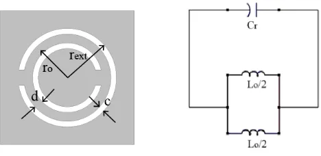
μ-negative structure that consists of array of split ring resonators (SRRs) [18], and later Smith et al. experimentally confirmed negative permeability of SRR unit [19]. SRR behaves as a magnetic dipole when it is excited by an axial magnetic field. The complementary split ring resonator (CSRR) is complementary dual element SRR behaving as an electric dipole. Both SRR and CSRR can be considered as parallel L-C resonant circuit which has same resonance frequency, i.e., f = 1/2π√LC. Equivalent circuit models of SRR and its dual part CSRR have already been shown in [20]. Fig. 1 shows the unit element of CSRR and its circuit model.
Figure 1. Basic CSRR unit and its equivalent circuit model.
Because of unconventional properties, metamaterial units are employed in antenna design for bandwidth and gain enhancement [21]. Also their sub-wavelength resonance benefits the size reduction of the antenna [22, 23]. The ground plane of the patch antenna loaded with CSRRs is reported for gain enhancement [24], and also dual band operation is achieved [25]. CSRR elements are etched periodically from the ground plane of the patch to reduce resonance frequency and increase the impedance bandwidth [26]. Triangle [27] and hexagon [28] shaped CSRRs are loaded on the radiating patches to achieve multiband operation. Ultra-wideband antennas with single [29] and dual notched bands [30] in WiMax/WLAN frequency band have also been proposed recently where CSRRs are loaded on patch. In this paper, CSRRs sub wavelength resonance due to its negative permittivity is utilized for achieving circular polarization. By loading CSRRs either on ground or on patch, an additional resonance can be produced which is close to the patch intrinsic resonance. The mutual orthogonal characteristics of these two resonances can produce circular polarization when the phase difference between them is reached near 90◦ which is done by adjusting the positions of the CSRRs in ground/patch.
3. ANTENNA DESIGN
(b) (a)
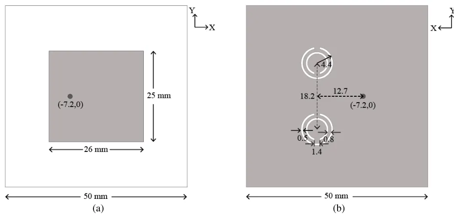
Figure 2. Geometry of the RMSA antenna with CSRRs loaded on ground (a) Top view and (b) Bottom view.
etched from the ground plane. The coaxial feed position and CSRRs relative position are determined to achieve the desired antenna characteristics. For the second antenna design, two CSRRs are loaded on the radiating patch. Substrate and ground plane dimensions for both antennas are (50×50) mm2. Both antennas exhibit circular polarization, and two CSRRs face back load in both antennas depending on the direction of the ring splits.
3.1. Antenna Design with CSRRs Loaded Ground
When two face to back CSRRs are loaded on the ground plane of an RMSA with orthogonal feed position to the ring splits, two degenerate modes with orthogonal polarization are generated at nearby frequencies. Fig. 2 represents the top view and bottom view of the antenna. CSRR itself is a resonating element instead of a good radiator, so it will couple the field to patch. The coupled field between CSRRs and patch is polarized in they-z plane while the patch inherent radiation is polarized in x-z plane.
3.2. Antenna Design with CSRRs Loaded Patch
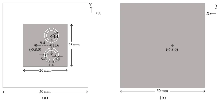
The radiating patch loaded with CSRRs can also yield circular polarization due to resonances at two close frequencies. While one of these resonances is patch intrinsic radiation polarized in x-z plane, the other resonance is caused by coupling of the field between CSRRs and patch having polarization iny-z plane. Top and bottom views of the antenna are presented in Fig. 3.
4. SIMULATED RESULTS
178 Dey, Mondal, and Sarkar
(b) (a)
Figure 3. Geometry of the RMSA antenna with CSRRs loaded on patch (a) Top view and (b) Bottom view.
Figure 4. Reflection coefficient characteristics of the antenna without with CSRR load.
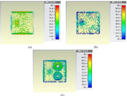
Figure 5 presents the surface current distributions over the patch for the two CP antennas. To illustrate the effect of CSRRs loading either on ground or on patch, current distribution of the unloaded RMSA is also shown in the diagram. For an unloaded RMSA currents are directed only along the two non-radiating edges of the patch, but when CSRRs are loaded on RMSAs currents seem to rotate for both CP antennas.
(b) (a)
(c)
Figure 5. Simulated surface current distribution over radiating patches (a) unloaded RMSA, (b) RMSA with CSRR on ground and (c) RMSA with CSRR on patch.
Figure 6. Variation of axial ratio plot of the antenna with CSRRs load.
Figure 7. Variation of gain plot of the antenna with CRSSs load.
180 Dey, Mondal, and Sarkar
Figure 8. Variation of total efficiency of the antenna with CSRRs load.
(b) (a)
Figure 9. Simulated far field radiation patterns of the antennas with CSRRs loaded on ground and patch at frequency 2.35 GHz in (a)x-z and (b)y-z plane respectively.
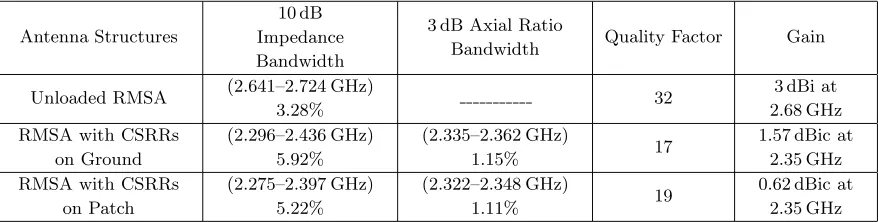
Table 1. Comparison of the simulated results of the antennas.
Antenna Structures
10 dB Impedance Bandwidth
3 dB Axial Ratio
Bandwidth Quality Factor Gain
Unloaded RMSA (2.641–2.724 GHz)
3.28% 32
3 dBi at 2.68 GHz RMSA with CSRRs
on Ground
(2.296–2.436 GHz) 5.92%
(2.335–2.362 GHz)
1.15% 17
1.57 dBic at 2.35 GHz RMSA with CSRRs
on Patch
(2.275–2.397 GHz) 5.22%
(2.322–2.348 GHz)
1.11% 19
0.62 dBic at 2.35 GHz
As the basic principles of achieving circular polarization in the two antennas are same, only the microstrip antenna with CSRRs loaded on patch has been fabricated for experimental verification of the simulated results. The next section presents measured reflection coefficient, gain, and radiation pattern of this antenna.
5. MEASURED RESULTS
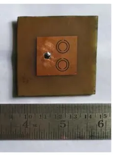
A photograph of the proposed CSRR loaded on patch is shown in Fig. 10. Measured reflection coefficient is in good agreement with the simulated result as shown in Fig. 11.
Measured impedance bandwidth of the antenna withS11<−10 dB is 110 MHz or 4.8%. Impedance bandwidth obtained in simulation is 119 MHz or 5.12% which is close to the measurement result. Gain and radiation pattern of the fabricated antenna are also measured in an anechoic chamber. The highest gain of this antenna is found at frequency 2.37 GHz, and the value is 1.28 dBic. Fig. 12 shows the simulated and measured gain variations of the antenna from frequency 2.3 GHz to 2.5 GHz.
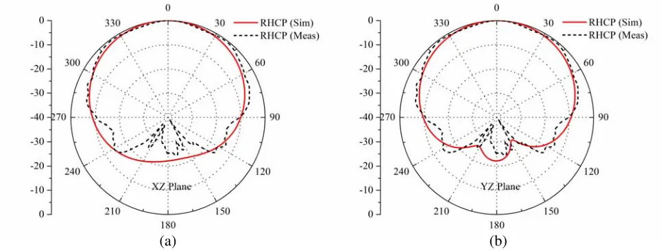
Measured radiation patterns of the antenna in both principal planes ( XZ and Y Z planes) at frequency 2.35 GHz are compiled with simulated results in Fig. 13. RHCP patterns in both planes show good degree of correlation. Minor discrepancies in results arise because of fabrication tolerance and error during measurement.
Figure 10. Photograph of the fabricated antenna.
Figure 11. Measured and simulated reflection coefficient characteristics.
182 Dey, Mondal, and Sarkar
(b) (a)
Figure 13. Simulated and measured far field radiation pattern at frequency 2.35 GHz in (a)XZ plane and (b)Y Z plane.
6. CONCLUSION
In this paper, a CSRR based rectangular microstrip antenna (RMSA) is designed for circular polarization. In the first antenna design, two circular CSRRs are embedded on the ground plane, and for the second antenna design, CSRRs are loaded on the radiating patch. Introduction of CSRRs on ground and patch is used to reduce the antenna size, and it also increases the impedance bandwidth. The impedance bandwidth of the antennas for S11 < −10 dB is between 2.3 and 2.4 GHz. Minimum axial ratios of the antenna with CSRR loaded on ground and patch are obtained as 1.48 dB at 2.35 GHz and 0.5 dB at 2.336 GHz, respectively. It is observed that gain variation is below 0.5 dB within the 3 dB axial ratio bandwidth. Higher isolation (> 20 dB) is maintained between co- and cross-polarized components. The quality factor and efficiency characteristics of the antenna are observed.
ACKNOWLEDGMENT
Authors acknowledge Mr. Amitesh Kumar for providing with the measurement facilities in SAMERR Kolkata for measurement of the fabricated antenna.
REFERENCES
1. Balanis, C. A., “Antenna theory: A review,”Proceedings of the IEEE, Vol. 80, No. 1, 7–23, 1992. 2. Kumar, G. and K. P. Ray, Broadband Microstrip Antennas, Artech House, 2003.
3. Sharma P. C. and K. C. Gupta, “Analysis and optimized design of single feed circularly polarized microstrip antennas,” IEEE Trans. Antennas Propag., Vol. 31, No. 6, 949–955, 1983.
4. Malviya, L., R. K. Panigrahi, and M. V. Kartikeyan, “Circularly polarized 2×2 MIMO antenna for WLAN applications,” Progress In Electromagnetics Research C, Vol. 66, 97–107, 2016.
5. Sharma, W. C., H. Kumar, and G. Kumar, “Single feed dual band circularly polarized stub loaded tunable microstrip patch antenna,” 2016 IEEE Asia-Pacific Microwave Conference (APMC), 1–4, 2016.
6. Qing, X. and Z. N. Chen, “Compact asymmetric-slit microstrip antennas for circular polarization,”
IEEE Trans. Antennas Propag., Vol. 59, No. 1, 285–288, 2011.
8. Alizadeh, F., C. Ghobadi, J. Nourinia, and R. Zayer,“Bandwidth enhancement of patch antennas loaded with complementary split-ring resonators,” 2014 IEEE 7th International Symposium on Telecommunications (IST), 224–229, 2014.
9. Ramachandran, A., S. V. Pushpakaran, M. Pezholil, and V. Kesavath, “A four port MIMO antenna using concentric square ring patches loaded with CSRR for high isolation,”IEEE Antennas Wireless Propag. Lett., Vol. 15, 1196–1199, 2016.
10. Rajeshkumar, V. and S. Raghavan, “A compact CSRR loaded dual band microstrip patch antenna for wireless applications,” 2013 IEEE International Conference on Computational Intelligence and Computing Research (ICCIC), 1–4, 2013.
11. Jha, N., R. Pandeeswari, and S. Raghavan,“A performance improved compact size microstrip antenna loaded with CSRR for GSM, WLAN/WiMAX and WAVE applications,” IEEE International Conference on Emerging Trends in Engineering, Technology and Science (ICETETS), 1–6, 2016.
12. Jie, C., L. Z. Gang, F. Lu, and Z. Shou-Zheng, “A multi-system and dual-band miniaturization microstrip antenna loaded with CSRR for CNSS applications,” 2014 IEEE 3rd Asia-Pacific
Conference on Antennas and Propagation (APCAP), 450–453, 2014.
13. Dong, Y., H. Toyao, and T. Itoh, “Design and characterization of miniaturized patch antennas loaded with complementary split-ring resonators,”IEEE Trans. Antennas Propag., Vol. 60, No. 2, 772–778, 2012.
14. Liu, X. Y., Z. T. Wu, Y. Fan, and E. M. Tentzeris, “A miniaturized CSRR loaded wide-beamwidth circularly polarized implantable antenna for subcutaneous real-time glucose monitoring,” IEEE Antennas Wireless Propag. Lett., Vol. 16, 577–580, 2017.
15. Simruni, M. and S. Jam, “A circularly-polarized compact wideband patch antenna loaded by metamaterial structures,”Progress In Electromagnetics Research C, Vol. 78, 93–104, 2017.
16. “CST Microwave Studio Manual,” ver. 14, Computer Simulation Technology, Framingham, MA. 17. Caloz, C. and T. Itoh, Electromagnetic Metamaterials: Transmission Line Theory and Microwave
Applications, Wiley-Interscince, 2006.
18. Pendry, J. B., A. J. Holden, D. J. Robbins, and W. J. Stewart, “Magnetism from conductors and enhanced nonlinear phenomena,” IEEE Transactions on Microwave Theory and Techniques, Vol. 47, No. 11, 2075–2084, November 1999.
19. Smith, D. R., Willie J. Padilla, D. C. Vier, S. C. Nemat-Nasser, and S. Schultz, “Composite medium with simultaneously negative permeability and permittivity,”Physical Review Letters, Vol. 84, No. 18, 4184–4187, May 2000.
20. Baena, J. D., J. Bonache, F. Martin, R. M. Sillero, F. Falcone, T. Lopetegi, M. A. Laso, J. Garcia-Garcia, I. Gil, M. F. Portillo, and M. Sorolla, “Equivalent-circuit models for split-ring resonators and complementary split-ring resonators coupled to planar transmission lines,”IEEE Transactions on Microwave Theory and Techniques, Vol. 53, No. 4, 1451–1461, 2005.
21. Ortiz, N., F. Falcone, and M. Sorolla, “Enhanced gain dual band patch antenna based on complementary rectangular split-ring resonators,” Microw. Opt. Technol. Lett., Vol. 53, No. 3, 590–594, 2011.
22. Limaye, A. U. and J. Venkataraman, “Size reduction in microstrip antennas using left-handed materials realized by complementary split-ring resonators in ground plane,” 2007 IEEE International Symposium in Antennas and Propagation Society, 1869–1872, 2007.
23. Ma, J. J., X. Y. Cao, and T. Liu, “Design the size reduction patch antenna based on complementary split ring resonators,”2010 International Conference in Microwave and Millimeter
Wave Technology (ICMMT), 401–402, 2010.
24. Pandeeswari, R. and S. Raghavan, “Microstrip antenna with complementary split ring resonator loaded ground plane for gain enhancement,”Microw. Opt. Technol. Lett., Vol. 57, No. 2, 292–296, 2015.
184 Dey, Mondal, and Sarkar
26. Lee, Y. and Y. Hao, “Characterization of microstrip patch antennas on metamaterial substrates loaded with complementary split-ring resonators,” Microw. Opt. Technol. Lett., Vol. 50, No. 8, 2131–2135, 2008.
27. Rajkumar, R. and U. K. Kommuri, “A triangular complementary split ring resonator based compact metamaterial antenna for multiband operation,” Wireless Personal Communications, Vol. 101, No. 2, 1075–1089, 2018.
28. Daniel, R. S., R. Pandeeswari, and S. Raghavan, “A miniaturized printed monopole antenna loaded with hexagonal complementary split ring resonators for multiband operations,”International Journal of RF and Microwave Computer-Aided Engineering, Vol. 28, No. 7, e21401, 2018.
29. Boopathi, R. R. and S. K. Pandey, “A CPW-fed circular patch antenna inspired by reduced ground plane and CSRR slot for UWB applications with notch band,”Microw. Opt. Technol. Lett., Vol. 59, No. 4, 745–749, 2017.
30. Xiao, B., X. Wang, and J. Zhao, “A dual band notched ultra-wideband antenna using complementary split ring resonators,” 2010 IEEE International Conference in Wireless