Analysis of Dualport Reader Antenna for UHF RFID Near-Field
and Far-Field Applications
Kui Jin1, Zhiyuan Geng2, Jingming Zheng5, Ye Liu6, Enze Zhang3, 4, *, Yang Yang6, and Xiaoxiang He6
Abstract—A dual-port reader antenna based on magnetic coupling in near-field (NF) and linear polarization in far-field (FF) is proposed for UHF RFID multiservice applications. The prototype consists of four straight dipoles fed by double-side parallel stripline structure with two feed ports. The proposed antenna can operate at different modes by feeding each corresponding port. In NF mode, a strong and uniform magnetic field can be generated over the interrogation zone. In FF mode, a linearly polarized performance can be obtained. The antenna prototype is printed onto a piece of FR4 substrate with an overall size of 180×180×1.6 mm3. The measured tests on reading range are carried out, and the results exhibit 100% reading rate for near-field tags within 100 mm and reading distance of far-field tags is 120 cm. Both simulated and measured results show good capability for near- and far-field applications.
1. INTRODUCTION
Radio frequency identification (RFID) technology has been widely adopted in a variety of applications such as contact-less payment, metro tickets, supply chain management, and tracking items [1, 2] over the years. Near- or far-field operation is used reliant on the tag and application characteristics. Near-field reading can be useful for objects surrounded by metals and liquids in their vicinity [3], and far-field communication is commonly used to achieve long read range. For this reason, there is significant research interest in developing special antenna with different modes that can be used in near- and far-field applications separately. In near-far-field region of the antenna, the radius is usually below 2D2/λ(Dis the maximum size of antenna andλis the wavelength). When the distance between the antenna and tag is increased, far-field of the antenna is the main function. Recent literature has investigated antennas with strong magnetic, inductive coupling for near-field applications. Reference [4] gives a method to obtain strong magnetic on a flexible plastic substrate. In [5], a zero-phase-shift-line (ZPSL) antenna is proposed for near-field tags. Also, complementary split ring resonator (CSRR) elements loading structure is adopted to generate strong magnetic field [6]. The antennas of [4–7] can be applied well in near-field application but not suitable for detecting far-field tags for low boresight gain. In inventory tracking and pharmaceutical industry, both near-field tags and far-field tags are employed [8]. Hence, a special antenna having multiple radiation properties separately for NFC and far-field communications is significant. The antennas in [9, 10] are proposed for RFID readers for near- and far-field operations, but the near- and far-field operations are either in different directions or in different frequency ranges. Reference [12] presents a multiband compact microstrip antenna including a segmented loop and a
Received 20 May 2018, Accepted 1 August 2018, Scheduled 14 August 2018 * Corresponding author: Enze Zhang (zhang [email protected]).
32 Jin et al.
meander line structure for portable wireless applications. In [14], varactor diodes are employed to modify radiation properties; they also introduce the complexity or nonuniform field distribution. In addition, [15] proposes a modular antenna with a spiral-shaped structure, to generate electric field instead of magnetic field for near-field applications. It is easily affected by liquids or metals in near field. Although slot edge [11] and circular-polarized antenna [13] are designed regardless of tag orientations, they bring problems of nonuniform and weak magnetic field and also achieve short read distance for far-field tags because electric vectors exist in all orientations.
In this paper, we present a novel antenna with dual modes separately working in UHF RFID near-field and far-near-field applications. The antenna exhibits a unique feature of changing the feed positions to switch the working mode for RFID multi-applications. In magnetic coupling mode, strong and uniform magnetic field distributions are obtained close to the antenna, in order to avoid the effects of liquids or metals. In far-field mode, the proposed antenna exhibits linear polarization for far-field tags. Measured performance in terms of reflection coefficient and tag detection is presented as follows.
2. ANTENNA LAYOUT AND PERFORMANCE
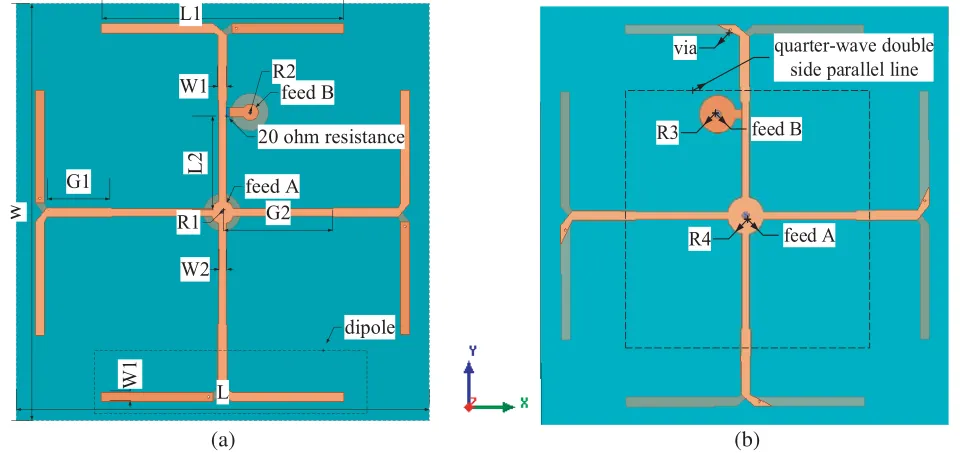
Antenna layout: Fig. 1 shows the configuration of the proposed dual-mode antenna. The antenna is composed of 4 straight dipoles fed by a quarter-wave double-side parallel stripline (QDSPSL) structure, printed on a 1.6 mm-thick FR-4 substrate with a dielectric constant of 4.4 and loss tangent of 0.02 (Fig. 1(a)). As seen, two feed ports (A and B) are fabricated on the proposed antenna. A 20 Ω resistance is adopted in port B to achieve good impedance matching. A double-side parallel stripline (QDSPSL) based on impedance transformers is introduced to match the input impedance (= 50 Ω) and also avoid radiation influence caused by itself for magnetic field on upper and lower surface counteracting. Feed arm lengths include two different parameters, one of which is set asλ/4 wavelength (G2 = 48 mm) and the other (G1) is to achieve better impedance matching and obtain large reading region for near-field tags.
Performance: Current distributions of this dual-mode antenna are shown in Fig. 2. As seen, when port A (port 1) is fed and port B (port 2) terminated on 50 Ω load, the current on four dipoles is kept in phase. Such a current distribution generates strong and uniform magnetic field over the interrogation
L1 L W G1 G2 W1 W1 W2 feed A feed B
20 ohm resistance
dipole
L2
R2
R1
quarter-wave double side parallel line
R3
R4 feed A
feed B via
(a) (b)
(a) (b)
Figure 2. Antenna currents distribution. (a) Current distribution when port 1 is active. (b) Current distribution when port 2 is active.
zone formed by four dipoles (Fig. 2(a)). When port B (port 2) is active and the other port terminated on 50 Ω load, far field of the antenna can be horizontally polarized. As seen in Fig. 2(b), currents on two horizontal dipoles are along the same direction for phase delay of currents on two horizontal dipoles caused by path differences. The direction of co-polarization is alongX-axis, while electric field strength caused by vertical dipoles above the antenna is lowered for opposite directed currents (ODC). So far field of the antenna is linearly polarized along X-axis.
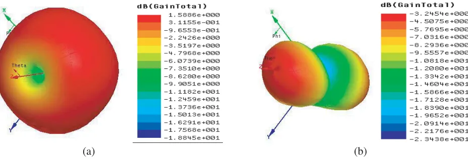
3-D radiation patterns of the proposed dual-mode antenna are shown in Fig. 3. As shown, in NF mode (Fig. 3(a)), the magnetic field can be generated along Z-axis, and boresight gain of antenna is also lowered for ODC (opposite directed currents). When the antenna works in FF-mode, the gain of −3.3 dB is exhibited (Fig. 3(b)).
(a) (b)
Figure 3. 3-D radiation patterns of the antenna. (a) Port 1 is active. (b) Port 2 is active.
34 Jin et al.
0.8 0.9 1.0
-30 -20 -10
S(2,2) (dB)
Frequency (GHz)
r=10 ohm r=20 ohm r=30 ohm
-80 0 80
-15 -10 -5 0
Gain (dB)
Theta (degree)
r=20 ohm r=30 ohm r=10 ohm
0.8 0 .9 1.0
-25 -20 -15 -10
S(1,2)(dB)
Frequency(GHz)
r=20 ohm r=30 ohm r=40 ohm r=50 ohm r=60 ohm
(a) (b)
(c)
Figure 4. Antenna performance for different values of resistance when port 2 is active. (a)S(2,2). (b) Gain. (c) S(1,2).
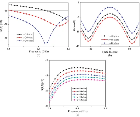
value of resistance is set to 60 Ω, the isolation is better than 20 dB within 800–850 MHz. To achieve long read distance for far-field tags and better isolation, the value of resistance is set 20 Ω.
Figure 5 exhibits the Co-pol and X-pol gains separately in XOZ and Y OZ planes. In Figs. 5(a) and 5(b), the Co-pol gain is about −3 dB for currents on two horizontal dipoles both along the same direction, and the direction of co-polarization is along X-axis. Meanwhile, currents on vertical dipoles are in opposite directions which makes electric field strength caused by vertical dipoles above the antenna lowered. Hence, value of X-pol gain is lowered, and cross-polarization is low.
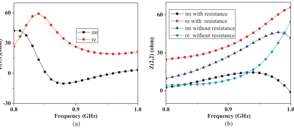
Input impedances for two portsZ(1,1) and Z(2,2) are also given in Fig. 6. As seen in Fig. 6(a), for port 1, the resonant frequency is at 850 MHz. The real part is 50 Ω, and the imaginary part is 0jΩ. In Fig. 6(b), comparison of Z(2,2) with and without resistance is given. As the resistance is loaded, the variation of input impedance changes slowly, and the real part increases from 30 Ω to 60 Ω within 0.8–1.0 GHz. The imaginary part changes from 5jΩ to 0jΩ, which broadens the bandwidth obviously. When there is no resistance adopted, the variation of input impedance changes fast, and the bandwidth shifts upwards. Also, the bandwidth is narrow for drastic variation of real and imaginary part of impedance with 0.8–1.0 GHz.
-60 -40 -20 0 20 40 60 -30
-20 -10
Co-Pol, X-Pol Gain (dB)
Theta (deg) Co-Pol X-Pol
-60 -40 -20 0 20 40 60
-40 -20 0
Co-Pol, X-Pol Gain (dB)
Theta (deg)
Co-Pol X-Pol
(a) (b)
Figure 5. Co-pol Gain and X-pol separately inXOZ plane and Y OZ plane at 920 MHz when port 2 is active. (a) XOZ plane. (b)Y OZ plane.
0.8 0.9 1.0
-30 0 30 60
Z(1,1)(ohm)
Frequency (GHz) im re
0.8 0.9 1.0
0 30 60
Z(2,2) (ohm
)
Frequency (GHz) im with resistance
re with resistance im without resistance re without resistance
(a) (b)
Figure 6. Input impedance for two ports. (a)Z(1,1), (b)Z(2,2).
respectively along X- and Y-axes above the antenna when port 1 is active. Field strength is up to −5 dBA/m at the height of 20 mm, and the strong magnetic field can be generated close to the antenna (input power is 1 W). The variation of magnetic field is also below 1 dBA/m in the interrogation zone (20 mm< X <140 mm, 20 mm< Y <140 mm), which indicates the uniform magnetic field.
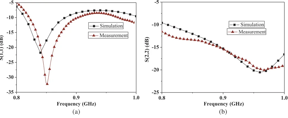
When one port is measured, the other port is terminated on 50 Ω load. The RFID reader antenna can work at near- and far-field operations within 820–880 MHz as reflection coefficients are below−10 dB. As seen in Fig. 8(a), in near-field mode (port 1 is fed), reflection coefficients are below −10 dB within 820–880 MHz. When the antenna works in far-field mode (port 2 is fed), reflection coefficients are below −10 dB within 800–1000 MHz in Fig. 8(b). The isolation between two ports better than 16 dB within 820–880 MHz is measured in Fig. 9.
36 Jin et al.
0 20 40 60 80 100 120 140 160
-15 -10 -5
|Hz| (dBA/m)
X/Y-axis (mm) X-axis
Y-axis
Figure 7. Magnetic field|Hz|, dBA/m, alongX andY-axis atZ = 20 mm when port 1 is active.
0.8 0.9 1.0
-35 -30 -25 -20 -15 -10 -5
Measurement
S(1,1) (dB)
Frequency (GHz)
Simulation
0.8 0.9 1.0
-25 -20 -15 -10 -5
Measurement
S(2,2) (dB)
Frequency (GHz)
Simulation
(a) (b)
Figure 8. Measured and simulated reflection coefficients of the antenna. (a)S(1,1). (b) S(2,2).
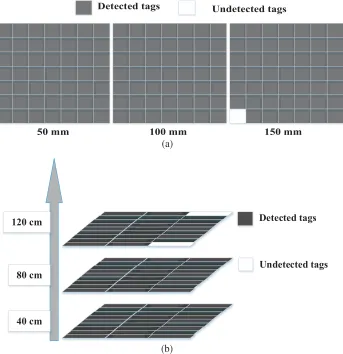
100 mm, 150 mm in magnetic coupling mode when the input power is set to 1 W. By increasing the height of zone from antenna surface, strength of magnetic field is lowered. When the height is at 50 mm and 100 mm, the magnetic field is strong to identify all tags in the region. Even when the height is at 150 mm, the magnetic field strength is still strong and above −23 dBA/m.
To evaluate the performance in a real scenario, the proposed antenna is integrated into a commercial desktop reader, and read range tests are carried out. Measurement system is set up in Fig. 11. In this test, the near-field button tag (J41) and far-field tag (Alien A9662 dipole-like) are chosen respectively. The J41 tag is a commercial Monza 4 microchip tag using a 6-mm-radius (out radius) loop antenna. The read sensitivity of the chip is 17.4 dBm. Identifying the tag J41 requires the component of the magnetic field (normal to the surface of the antenna) to be at least −24 dBA/m. The input power of reader is set to 25 dBm.
0.8 0 .9 1.0 -25
-20 -15
S(1,2) (dB)
Frequency(GHz)
S(1,2)
Figure 9. MeasuredS(1,2) of the antenna between two ports.
50 mm 100 mm
|Hz|, dBA/m
150 mm
38 Jin et al.
Reader
Antenna
7×7 tag
Near-field tag Far-field
tag
Figure 11. Measurement on read range for near-field and far-field tags.
50 mm 100 mm 150 mm
Detected tags Undetected tags
40 cm 80 cm
120 cm Detected tags
Undetected tags
(a)
(b)
maximum read distance for near-field tag is about 150 mm. When port 2 is fed, the antenna works in far-field mode. Far-field tags are tested alongX-axis (Fig. 12(b)), and 9×3 far-field tags are adopted. The read distance is up to 120 cm. The proposed antenna shows good capability for near- and far-field tag readings.
3. CONCLUSION
In this paper, a novel antenna with dual-port for near/far-field RFID applications is presented. Far-field radiation for linear polarization and near-field operation based on magnetic field coupling are separately obtained by feeding each corresponding port. The proposed antenna shows good capability for near-and far-field tag readings. Design of changing the feed positions to switch the working modes of the antenna for multi-applications also has a good prospect in projects.
ACKNOWLEDGMENT
This work is supported by “the Fundamental Research Funds for the Central Universities”, No. 30920140122005. There is no conflict of interest regarding the publication of this paper.
REFERENCES
1. Zuo, Y., “Survivable RFID systems: Issues, challenges, and techniques,”IEEE Trans. Syst., Man,
Cybern. C, Appl. Rev., Vol. 40, No. 4, 406–418, 2010.
2. Caso, R., A. Michel, A. Buffi, P. Nepa, and G. Isola, “A modular antenna for UHF RFID near-field desktop reader,”Proc. RFID Technol. Appl. Conf., 204–207, 2014.
3. Nikitin, P. V., K. V. S. Rao, and S. Lazar, “An overview of near field UHF RFID,” Proc. IEEE
Int. Conf., RFID, 167–174, Mar. 2007.
4. Daiki, M. and E. Perret, “Near-field modular antenna concept with configurable reading area for RFID applications,” IEEE Transactions on Antennas & Propagation, Vol. 65, No. 3, 1015–1025, Mar. 2017.
5. Shi, J., X. Qing, and Z. N. Chen, “Electrically large zero-phase-shift line grid-array UHF near-field RFID reader antenna,”IEEE Transactions on Antennas&Propagation, Vol. 62, No. 4, 2201–2208, 2014.
6. Pakkathillam, J. K. and M. Kanagasabai, “A novel UHF near-field RFID reader antenna deploying CSRR elements,”IEEE Transactions on Antennas&Propagation, Vol. 65, No. 4, 2047–2050, 2017. 7. Zheng, J., C. Zhou, Y. Yang, X. He, and C.-Y. Mao, “QDSPSL-fed straight dipoles antenna array for UHF RFID near-field applications,” Progress In Electromagnetics Research Letters, Vol. 72, 107–112, 2018.
8. “Market of RFID systems,” Impinj, Inc., Seattle, WA, WSA2015, [Online], Available: http://www.impinj.com/markets/.
9. Oliver, R. A., “Broken-loop RFID reader antenna for near field and far field UHF RFID tags,” U.S. Design Patent D570, 337 S, 2008.
10. Qing, X. and Z. N. Chen, “Antenna for near field and far field radio frequency identification,” U.S. Patent Appl. Pub. US 20100026439 A1, 2010.
11. Pakkathillam, J., M. Kanagasabai, and M. Alsath, “A compact multiservice UHF RFID reader antenna for near field and far field operations,” IEEE Antennas & Wireless Propagation Letters, Vol. 16, No. 99, 149–152, 2017.
12. Forouzannezhad, P., A. Jafargholi, and A. Jahanbakhshi, “Multiband compact antenna for near-field and far-near-field RFID and wireless portable applications,”IET Microwave Antennas Propagation, Vol. 11, No. 4, 535–541, 2017.
40 Jin et al.
14. Bitnun, A. and E. Al, “A reconfigurable passive UHF reader loop antenna for near-field and far-field RFID applications,”IEEE Antennas&Wireless Propagation Letters, Vol. 11, No. 4, 580–583, 2012.