Coaxial Feed MIMO Patch Antenna Wi-Max Wireless Application
at 4.6 GHz Frequency
V. Sindhuja, K.Satyavathi, Dr.M.Narsingh Yadav
Final M.Tech Student, Associate professor, HOD
Department of Electronics and Communication Engineering MRIET, Hyderabad, TS, India.
ABSTRACT:-
The field of mobile and wireless communication is growing at very fast rate covering many technical areas. Wireless local area network (WLAN) and Worldwide Interoperability for Microwave Access (WiMAX) technology is most rapidly growing area in the modern wireless communication. This gives users the mobility to move around within a broad coverage area and still be connected to the network. This provides greatly increased freedom and flexibility. For the home user, wireless has become popular due to ease of installation, and location freedom. Among wireless devices antenna is quite important component. So, there is continuously increasing requirements of efficient and high performance antenna. The features of antenna which every technology requires are light weight, small in size and low cost etc. Another important desired properties of antenna are wide bandwidth and resonant at multiple frequency.
Next Generation devices have also more than one application embedded in single device so antenna supporting more than one band is required and multiband operation of antenna is another challenge. Almost all these requirements can be fulfilled by Microstrip patch antenna
The main objective of this report is to design Coaxial Fed Dual band
Microstrip antennas for WiMAX
applications using four rectangular antennas. The designed antennas resonate at two frequencies 2.4GHz, 4.6GHz and 5.5GHz. The bandwidth is also increased upto a sufficient level by having slots in the patches. The various parameters like return loss, gain, radiation pattern and bandwidth have been studied and plotted for each simulated antenna. The parametric study of each of the designed antenna is also done. The simulated results of the effect of the various parameters like length of the patch, location of the feed point and position of the slot are also shown.
KEY WORDS: Dual band antenna, coaxial feed, microstrip antenna, WIMAX
INTRODUCTION
Presently wireless communication, by measure is the fastest growing segment of the communication field. There are many government and commercial applications such as mobile radio, Satellite
communication and Wireless
The vision of the wireless communication supporting information exchange between people and devices is the communication frontier of the next few decades. This vision will allow multimedia communication from anywhere in the world. In the last few years, the development of wireless local area
networks (WLAN) and WIMAX
(Worldwide Interoperability for Microwave Access) represented one of the principal interests in the information and communication field. Also, in today‟s environment, technology demands antennas which can operate on different wireless bands and should have different features like low cost, minimal weight, low profile and are capable of maintaining high performance over a large spectrum of frequencies.
In this era of next generation networks we require high data rate and size of devices are getting smaller day by day. In this evolution two important standards are Wi-Fi (WLAN) and Wi-MAX. Wireless local area network (WLAN) and Worldwide Interoperability for Microwave Access (Wi-MAX) technology is most rapidly growing area in the modern wireless communication. This gives users the mobility to move around within a broad coverage area and still be connected to the network. This provides greatly increased freedom and flexibility. For the home user, wireless has become popular due to ease of installation, and location freedom. For success of all these wireless applications we need efficient and small antenna as the size of the device is becoming smaller and smaller. This being the case, portable antenna technology has grown along with mobile and cellular technologies. It is important to have the best
performance antenna for a device. The best performance antenna will improve transmission and reception, reduce power consumption, last longer and improve marketability of the communication device. Microstrip antennas (MSA) have some good features written above. Due to these advantages, Microstrip antennas (MSA) are well suited for WLAN/WiMAX application systems. Microstrip antennas (MSA) have some disadvantages also like narrow bandwidth, low gain etc.
Next Generation devices have also more than one application embedded in single device so antenna supporting more than one band is required and multiband operation of antenna is another challenge. Dual-band wireless phones have become popular recently because they allow using the one phone in two networks that have different frequencies. Tri-band phones have also gained popularity. Still, there exist more than three frequency bands used for wireless applications. The systems having multi-band operation require antennas that resonate at the specified frequencies.
WLAN (wireless local area network) and its standards
A wireless local area network (WLAN) links two or more devices using some wireless distribution method and usually providing a connection through an access point to the wider internet. The IEEE standards for wireless local area network were developed by IEEE and include four subsets of Ethernet based protocol standards [4]:
802.11n
In 1997, the Institute of Electrical and Electronics Engineers (IEEE) created the first WLAN standard. They called it 802.11 after the name of the group formed to oversee its development. Unfortunately, 802.11 only supported a maximum network bandwidth of 2 Mbps - too slow for most applications.
WiMAX(Worldwide Interoperability for Microwave Access) and its
Standards
WiMAX (Worldwide Interoperability for Microwave Access) is the next-generation of wireless technology designed to enable pervasive, high-speed mobile Internet access to the widest array of devices including notebook PCs, handsets, smart phones, and consumer electronics such as gaming devices, cameras, camcorders, music players, and more. WiMAX is a telecommunications protocol that provides fixed and mobile Internet access. The name WiMAX was created by the WiMAX forum which was formed in June 2001 to promote conformity and interoperability of the standard. The current WiMAX revision provides up to 40 Mbit/s with the IEEE 802.16m update expected to offer up to 1 Gbit/s fixed speeds. The IEEE 802.16 standard forms the basis of 'WiMAX' and is sometimes referred to colloquially as "WiMAX", "Fixed WiMAX", "Mobile WiMAX", "802.16d" and "802.16e" Clarification of the formal names are as follow:
802.16-2004 is also known as 802.16d, which refers to the working party that has developed that standard. It is sometimes referred to
as "Fixed WiMAX," since it has no support for mobility.
802.16e-2005, often abbreviated to 802.16e, is an amendment to 802.16-2004. It introduced support for mobility, among other things and is therefore also known as "Mobile WiMAX".
PROPOSED SYSTEM
In high-performance aircraft, spacecraft, satellite and missile applications, we have small size, less weight, low cost, high performance, ease of installation, and aerodynamic profiles are constraints, so we require low profile antennas. Presently there are many other government and commercial applications, such as mobile radio and wireless communications that have similar specifications. To meet these requirements, Microstrip antennas can be used. These antennas are low profile, conformable to planar and non planar surface, simple and inexpensive to manufacture using modern printed circuit technology, mechanically robust when mounted on rigid surfaces, and when the particular patch shape and mode are selected; they are very versatile in terms of resonant frequency, polarization, pattern and impedance. In addition by adding the load between patch and ground plane such as pins, adaptive elements with variable resonant frequency, impedance, polarization and pattern can be designed.
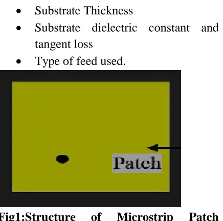
An example of Microstrip patch antenna with rectangular shaped patch and feed from Coaxial feed is shown in fig.1 below. Important parameters in designing Microstrip patch antennas are:
Substrate Thickness
Substrate dielectric constant and tangent loss
Type of feed used.
Fig1:Structure of Microstrip Patch antenna with rectangular shaped patch.
COAXIAL FEED
The Coaxial feed or probe feed is a very common technique used for feeding Microstrip patch antennas. The inner conductor of the coaxial connector extends through the dielectric and is soldered to the radiating patch, while the outer conductor is connected to the ground plane.. The coaxial feed, using Huygens‟s principal, can be modeled by a cylindrical band of electric current flowing on the center conductor from the bottom to top along with the annular ribbon of magnetic current in the ground plane. An idealization that simplifies the computation is to replace the electric current by a uniform line current ribbon. To determine the probe impedance for a microstrip antenna, the canonical problem of a parallel plate waveguide fed by a coaxial line has been analyzed using the integral formulation. The geometry for calculating the impedance is shown
DESIGN OF DUAL BAND
MICROSTRIP ANTENNA
The three antennas are designed for dual band WLAN applications which resonate at 2.4GHz and 5.2GHz.For designing these antennas coaxial feeding technique is used here. The return loss and smith chart have also been studied.
Design procedure of Microstrip Patch Antenna
The arrangement of an arbitrary shaped patch microstrip antenna is given in Figure . It consists of patch, substrate, ground plane and feeding point. A patch is a two-dimensional antenna element, which is often rectangular in shape. It is of a very thin thickness of metallic strip on top of a material known as the substrate with
thickness h (h«λo, usually
0.003λo≤h≤0.05λo, where λo is free space wavelength) above a ground plane.[2] For rectangular patch, the length L of the element is usually λo/3<L<λo/2. The strip (patch) and the ground plane are separated by a dielectric (substrate).
Figure 2: Layout of Patch Antenna
:Frequency of operation (fr): The resonant frequency of the antenna must be selected appropriately. The frequency ranges and the bandwidth requirement for various wireless applications are shown. The resonant frequencies selected for my design is 2.4GHz, 4.6GHz and 5.2GHz for WLAN Dielectric constant of the substrate (εr): The dielectric constant of substrate material plays an important role in the patch antenna design. A substrate with a high dielectric constant reduces the dimensions of the antenna but it also affects the antenna performance. So, there is a trade-off between size and performance of patch antenna.
Height of dielectric substrate (h): For the Microstrip patch antenna to be used in wireless communication systems, it is essential that the antenna is not bulky. Hence, the height of the dielectric substrate should be less.
Design procedure
The design procedure of single band microstrip patch antenna using rectangular patch is carried out step by step[1,2] is given below;
(a) Substrate Selectivity: Selection of suitable substrate of appropriate thickness is the first step in the design procedure of any microstrip antenna. Bandwidth and radiation efficiency increase with substrate thickness. The radiation efficiency of the microstrip antenna depends largely on the permittivity of the dielectric. It affects both the width, in turn the characteristic impedance and the length resulting in an altered resonant frequency and reduced transmission efficiency .
(b) Calculation of width of patch:
The width of the antenna is calculated by equation
(c) Calculation of effective dielectric constant: The effective dielectric is calculated by equation
(d) Calculation of the effective length: The effective length is calculated using equation
(e) Calculation of the length extension: The length extension is calculated using equation
(f) Calculation of actual length of patch: The actual length is obtained by equation,
(h) Coaxial feed position:
The inner conductor of the coaxial is connected to the radiation patch and the outer conductor to ground plane. The feed point should be near one of the two radiating edges . Rin for coaxial is given by equation
SIMULATION AND MEASUREMENT RESULTS
length at appropriate position to make it dual band.Before getting the optimum simulated results in terms of return loss, resonant frequencies, bandwidth and impedance matching we have done the parametric simulation study of the designed antennas. Design of Coaxial fed dual band microstrip antenna for WLAN application using rectangular patch at 2.4GHz
In our design firstly we calculate the parameters of the microstrip patch antenna to resonate at 2.4GHz by using the above equations After getting the desired simulated results for 2.4GHz frequency, we went for cutting slot in the patch to make it resonate at another frequency also.
Design of Coaxial fed dual band microstrip antenna for WLAN application using rectangular patch at 4.6GHz
In our design firstly we calculate the parameters of the microstrip patch antenna to resonate at 4.6GHz by using the above equations After getting the desired simulated results for 4.6GHz frequency, we went for cutting slot in the patch to make it resonate at another frequency also.
Design of Coaxial fed dual band microstrip antenna for WLAN application using rectangular patch at 5.5GHz
In our design firstly we calculate the parameters of the microstrip patch antenna to resonate at 5.5GHz by using the above equations After getting the desired simulated results for 5.5GHz frequency, we went for cutting slot in the patch to make it resonate at another frequency also.
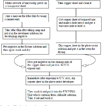
FABRICATION STEPS OF THE MICROSTRIP PATCH ANTENNA This chapter describes the entire procedure for fabrication of a microstrip patch antenna. Some fabricated antennas are also presented that are designed and simulated in chapter 5. Fabrication process:
There are various steps followed when we fabricate an antenna. This can be shown via a flow chart:
Fig 3: Fabrication Steps
Some fabricated microstrip patch antenna:
Fabrication of Microstrip antenna simulated is carried out at PCB FABRICATION LAB . Images of the fabricated microstrip patch antennas of three different shaped patches for WLAN application is shown
CONCLUSION
In this thesis Microstrip Patch antenna with different shapes for WLAN application has been simulated and fabricated. In this thesis overview of Microstrip antenna has been discussed with advantage and disadvantage of Microstrip Patch Antenna. It can be concluded that Microstrip Patch antenna is advantageous over wire antennas for WLAN devices as requirement of antenna to be conformal.
Further Literature review is presented on different dual band antennas for WLAN applications. In literature review different microstrip antennas are discussed which are published by different authors. It is concluded that lots of research is going on in field of multiband and broad band antenna design. So after literature review objectives were defined to design dual band Microstrip Patch Antenna for WLAN applications. Design computation and analysis method for Microstrip Patch antenna design is discussed for example transmission line model, cavity model etc. It is inferred that different shapes of patch produces different kind of resonance and different bandwidth. So Microstrip Patch antennas with different shapes of patches are simulated for 2.4 GHz and 5.2 GHz frequencies, which can be used for WLAN applications.
FUTURE SCOPE
Although an infinite amount of research has done for optimum antenna designs for wireless applications but still there are many things yet to be done in microstrip antenna. In this thesis, a microstrip patch antenna up to dual band has been presented. Next, one can work out on design the microstrip patch
antenna in such a configuration so that we can achieve more than two bands with a sufficient bandwidth. There are various optimization techniques on which one can extend our work to have multiband antenna with sufficient bandwidth i.e. making the antenna broadband. Next, the work on the miniaturization of the microstrip antennas and reduction of mutual coupling between elements in the array can be carried out. One can also extend our work by applying various optimization techniques like
PSO
Neural network approach to optimize the design
REFERENCES
[1] S.-W. Su and C.-T. Lee, “Low-cost dual-loop-antenna system for dual-WLAN-band access points,” IEEE Trans. Antennas Propag., vol. 59, no. 5, pp. 1652–1659, May 2011.
[2] Y. Li, Z. Zhang, W. Chen, Z. Feng, and M. F. Iskander, “A dual-polarization slot antenna using a compact CPW feeding structure,” IEEE Antennas Wireless Propag. Lett., vol. 9, pp. 191–194, 2010.
[3] Y. Li, Z. Zhang, J. Zheng, and Z. Feng, “Compact azimuthal omnidirectional dual-polarized antenna using highly isolated collocated slots,” IEEE Trans. Ant. Propag., vol. 60, no. 9, pp. 4037–4045, Sep.
[4] W. Han, X. Zhou, J. Ouyang, Y. Li, R. Long, and F. Yang, “A six-port MIMO antenna system with high isolation for 5-GHz WLAN access points,” IEEE Antenna Wireless Propag. Lett., vol. 13, pp. 880– 883, 2014.
IEEE Antenna Wireless Propag. Lett., vol. 10, pp. 1039–1042, 2011.
[6] H. Wang, L. Liu, Z. Zhang, and Z. Feng, “Wideband tri-port MIMO antenna with compact size and directional radiation pattern,” Electron. Lett., vol. 50, no. 18, 2014, pp. 1261–1262.
[7] X. Zhou, X. Quan, and R. Li, “A dual-broadband MIMO antenna system for GSM/UMTS/LTE and WLAN handsets,”
IEEE Antenna Wireless Propag. Lett., vol. 11, pp. 551–554, 2012.
[8] W.-J. Liao, S.-H. Chang, J.-T. Yeh, and B.-R. Hsiao, “Compact dual-band WLAN diversity antennas on USB dongle platform,” IEEE Trans. Antennas Propag., vol. 62, no. 1, pp. 109–118, Jan. 2014. [9] C.-Y. Chiu and R. D. Murch, “Compact four-port antenna suitable for portable MIMO devices,” IEEE Antennas Wireless Propag. Lett., vol. 7, pp. 142–145, 2008. [10] R. Karimian, H. Oraizi, S. Fakhte, and M. Farahani, “Novel F-shaped quad-band printed slot antenna for WLAN and WiMAX MIMO Systems,” IEEE Antenna Wireless Propag. Lett., vol. 12, pp. 405– 408, 2013.
.
Ms.V.Sindhuja completed B.Tech in Electronics&communication Engineering
in 2015 from Institute of
Aeronautical Engineering. Affiliated to JNTU-Hyderabad, Telangana, India and
M.Tech in Wireless & Mobile Communications in 2017(pursuing) from Malla Reddy Institute of Engineering & Technology ,Affiliated to JNTU Hyderabad, Telangana, India.
.Author profile
K.Satyavathi Mtech(Ph.d) completed B.tech 2004 in Electronics and communication Engineeering from Nagarjuna institute of engineering and technology, M.tech in
digital system &computer
electronics(DSCE) from jntuh. Working as an assistant professor in Malla reddy institute of engineering and technology.
Mr. Narsingh Yadav is currently working as
Head of the Department in Malla Reddy Institute
of Engineering and Technology, Affiliated to
JNTU Hyderabad,Telangana .He has
completed his B.Tech from Guru nanak