DOI: 10.12928/TELKOMNIKA.v15i4.7228 1501
Important Parameters for Hand Function Assessment
of Stroke Patients
H. Abdul Rahman*1, C. F. Yeong2, K. X. Khor3, E. L. M. Su4 1
Department of Mechatronic and Robotic Engineering, Faculty of Electrical and Electronic Engineering, Universiti Tun Hussein Onn Malaysia, 86400, Johor, Malaysia
2
Centre of Artificial Intelligence and Robotics (CAIRO), Universiti Teknologi Malaysia 3
Malaysian-Japan International Institute of Technology, Universiti Teknologi Malaysia 4
Faculty of Electrical Engineering, Universiti Teknologi Malaysia *Corresponding author, e-mail: [email protected]
Abstract
Clinical scales such as Fugl-Meyer Assessment and Motor Assessment Scale are widely used to evaluate stroke patient's motor performance. However, the scoring systems of these assessments provide only rough estimation, making it difficult to objectively quantify impairment and disability or even rehabilitation progress throughout their rehabilitation period. In contrast, robot-based assessments are objective, repeatable, and could potentially reduce the assessment time. However, robot-based assessment scales are not as well established as conventional assessment scale and the correlation to conventional assessment scale is unclear. This paper discusses the important parameters in order to assess the hand function of stroke patients. This knowledge will provide a contribution to the development of a new robot-based assessment device effectively by including the important parameters in the device. The important parameters were included in development of iRest and yielded promising results that illustrate the potential of the important parameters in assessing the hand function of stroke patients.
Keywords: motor assessment scale, rehabilitation, robotic, stroke, assessment
Copyright © 2017 Universitas Ahmad Dahlan. All rights reserved.
1. Introduction
The use of robotic devices for physical rehabilitation of the upper limb following brain injury can assist physiotherapists in rehabilitation program [1]. In addition, the use of these devices will lead to similar or larger improvements of motor function than conventional therapy [2,3]. These devices can increase the intensity of the training beyond what is currently possible [4], as well as repetitive [5], systematically [6] and encourage motivation through game-like virtual reality technology [7-9] with minimal supervision [10]. Besides, robotic devices can measure the patient's sensory-motor performance precisely and objectively by integrating sensors [11]. Such data could be used to redefine the rehabilitation strategy or even reconstruct the clinical score [4,12]. Moreover, robotic measure can also provide immediate feedback on patient's progress and would reduce the subjectivity inherent in most of the conventional assessment scales [13].
An added benefit of robotic rehabilitation devices is that the built-in technology can accurately measure kinematic information such as position, velocity and force about the user’s movements as they undergo robotic training. Conversely, conventional assessment scale is limited by subjective observation of the therapist and patient. There are two potential benefits if kinematic information could be converted into clinical meaningful information [14]: i) The quantitative measurement of patient's performance allows more effective rehabilitation program to be customized. The rehabilitation will be data-driven and training parameters tuned to ensure the meaningful training, ii) Automated and quantitative functional assessments would reduce the subjectivity inherent in many of the conventional assessment scales.
2. Mechatronic Approach
collected from various works around the world will be very useful for researchers who require a wide overview on stroke quantitative assessment device. In addition, the review of the important parameter require for the effective design of the device should provide an excellent starting point for researchers who are looking for a one-stop reference that provides good fundamental knowledge to jump-start their own research. To complement all these, a meticulous list of references is provided for those interested in probing the issues raised in this paper further. Finally, a new approach to assess the hand function of stroke patients is also explained in this paper.
A number of studies have examined the relationship between the kinematic variables measured by robots (including completing time, smoothness, speed accuracy and force produced) and the conventional assessment scales used for stroke survivors. Several studies [3,12,15-18] tested the performance of the extracted kinematics variables from MIT-Manus, HapticKnob, ArmeoSpring, IE2000 haptic joystick, wrist/shoulder-elbow device and NJIT RAVR system to predict the several clinical score such as FMA, Motor Status Score (MSS) and Motor Power scale (MP). The tasks were basically the subject need to perform robotic assessment unconstraint or resistive movements dependent on the device with game like virtual reality environment.
Besides robotic assessment, some research used motion capture to assess the performance of hand function of stroke patients. For example, Murphy et. al. [19] recorded the movement trajectories of stroke patients during drinking from a glass task and Chang et. al [20] asked the stoke patients to perform the reaching forward task with their affected limb as fast as possible where the paper cup as a target by using a motion capture system.
Wearable sensors also could address the limitation of conventional assessment scale [21-23].Wearable sensors could be used as quantitative assessment tools or as an addition to observational clinical tools. Sensors such as accelerometer and inertia sensor have the ability to capture specific patterns of movement relating to motor disabilities. Furthermore, this system allows voluntary movements of the subject without assistance from others. Previous studies showed that the kinematic variables extracted from the wearable sensors can be used to predict the conventional assessment scale score in the stroke populations [24-26]. Subjects were asked to perform several tasks such as drinking, placing the hand from lap to a table, push and pull a weight across a table, lifting a pencil, flipping a card, turning a key and etc. The recorded kinematics data was then analysed and correlated with the clinical scale scores using linear regression techniques. Table 1 shows the summary of the mechatronics approach for quantitative assessment of the hand function.
elbow movements with Virtual reality environment
MSS MP
R = 0.59
R = 0.53
movement was excluded
HapticKnob Forearm rotation and Hand opening/closing Resistive movements with virtual reality environment FMA MI MAS MoAS
R = 0.67
R = 0.69
R = 0.60
R = 0.79
Reaching movement was excluded
Armeo Spring Whole upper limb Unconstrained movements with Virtual reality environment GRASSP ARAT SCIM
Adjusted R2= 0.78 Adjusted R2= 0.73 Adjusted R2= 0.77
Attach/detach and tune the parameter to adapt the user hand are time consume IE2000 haptic joystick Wrist and forearm rotation Unconstrained movements with Virtual reality environment FMA ARAT JT MAL
R ≤ 0.74
R ≤ 0.83
R ≤ 0.63
R ≤ 0.57
Reaching and hand opening/closing movement was excluded Wrist and shoulder-elbow device Shoulder, elbow and wrist Resistive movements with virtual reality environment FMA MP MSS
R ≤ 0.55
N/A N/A
Hand manipulation movement was excluded
NJIT RAVR Whole upper limb
Unconstrained movements with Virtual reality environment
JTHF adjusted R2 ≤ 0.56 Complex tasks
Motion capture Whole upper limb Voluntary movements with real environment FMA ARAT MoAS
R ≤ 0.53
R ≤ 0.81
R ≤ 0.04
Attach/detach markers is time consuming.
Wearable sensors Whole upper limb Voluntary movements with real environment FMA MAS WMFT CM FAS
R ≤ 0.53
R ≤ 0.40 N/A N/A N/A
Attach/detach sensors is time consuming.
Abbreviation: FMA, Fugl-Meyer Assessment; MSS, Motor Status Score; MoAS, Modified Ashworth Scale; MI, Motricity Index; MAS, Motor Assessment Scale; GRASSP, Graded and Redefined Assessment of Strength, Sensibility and Prehension; ARAT, Action Research Arm Test; SCIM, Spinal Cord Independence Measure; WMFT, Wolf Motor Function Test; CM, Chedoke McMaster; FAS, Functional Ability Scale.
3. Main Issues to Discuss
A number of moderate to high and statistically significant correlation have been identified between the kinematic variables and conventional assessment scale score. Although researchers have found the strong correlation between the kinematic variable scores and clinical score, it remains unclear how robotic technology is related to conventional assessment scales for measuring outcome [15,27].
In order to train and assess the functional movement that involves upper limb function principle, generally a robotic rehabilitation system with a large number of degree of freedom (DOF) is needed. Such robotic rehabilitation systems are often large and complex, requiring technical assistance and making them unsuited for decentralized use at hospitals, rehabilitation centres or homes. Generally, the more complex the mechanical design, the more expensive, less safe and less number of potential users it has [28]. However, these robotic rehabilitation systems are valuable for assessment purposes where the user's upper limb is exposed to large workspace including reaching and hand manipulation movements.
In neuroscience studies, human generally use regular motion patterns involving fewer DOF or synergies [29] to simplify motion control. Motor synergies in humans involve the natural selection of muscles and joints and their coordinated movements in order to move as a single functional unit to perform a task. Thus, it may be possible to use these motion invariance to simplify the design of dedicated rehabilitation devices that can be used for both training and assessment. For example, in reaching movements, the hand follows approximately a straight line path from the start point to the target [30] and predominantly confined to the sagittal plane [29]. ARM Guide and ReachMAN have an active DOF for reaching movement, which simplifies the design considerably and makes the device safer and cheaper relative to an exoskeleton system with 6 DOF.
functions. Thus, the basic movement of the upper limb (reaching and hand manipulation) must be included in the robotic rehabilitation training and assessment process. Besides, the motion capture's marker and wearable sensors are portable and would be more suitable for quantitative assessment purposes where the user's upper limb is exposed to the large workspace. However, the process of attaching and detaching the marker and the sensors together with calibration process is time consuming, probably similar or even longer than time taken using conventional method.
By using the motion capture system and wearable sensors, voluntary movement can be performed by the subjects without active intervening assistive or resistive force. Therefore, the data collected during the assessment process were recorded from the voluntary movement afforded by the subjects themselves. Good correlation between clinical scores and extracted kinematic variables of these systems have been found. During the assessment process using the robotic system, the unassisted modes were used where no force was generated by the device, and the movement was solely determined by the movement of the patient. However, the actuator from the robotic device should be back-driveable or has good control algorithm to allow voluntary movements performed by the subject. Celik et. al [17] reported that an unactuated rehabilitation devices or affordable motion capture systems can provide an inexpensive and practical way of conducting clinically correlated assessments. With this in mind, a non-motorized device can be implemented to represent the subject’s free movement with no external interference. Despite the absence of actuation, movements of the subjects can still be accurately sampled and recorded. On the other hand, the non-motorized system would be able to increase the safety of the device during user interaction and also reduces the development cost. Therefore, it would be beneficial if a simple, non-motorized system with few DOF can be designed to assess the upper limb function that involves reaching and hand manipulation movements as efficiently as existing complex robotic devices.
Several strategies have been used to assess the upper limb function. However, most of the strategies were used to assess the motor function by moving their upper limb to the target position without a clear guide on the computer screen. These strategies are strongly associated with proprioception or the ability to sense the position of the body in time and space [31]. Stroke patients usually depend on visual function when they move part of their body for example, during eating and walking because they have impaired proprioception [32,33]. Tasks should have a clear guidance path so that the subject understands easily what they should do. In previous studies, subjects were expected to move along in a straight trajectory from start to end positions, but the visual guidance of the desired path was not displayed. Performance was based on deviation value from the desired straight line [17]. With the presence of the guidance path or customized desired trajectory, the deviation can be calculated based on the customized path. However, the correlation between the clinical score and kinematic variable using this concept required further study.
4. Proposed Method
For the quantitative assessment method, kinematic movement analysis can provide more specific information on movement components and strategies. Although this method requires special equipment and training, it is most applicable in a research setting [19,27]. Kinematics describes the movements of the body through space and time, including linear and angular displacements, velocity, and acceleration, but without reference to the forces involved [27,34]. Therefore, the wearable sensors and imaging techniques which allow voluntary movement of the upper limb can be used to provide the quantitative assessment. By combining the robotic design concept, motion capture system and wearable sensor concept, a non-motorized system which allows voluntary movement can be developed as a tool to quantitatively assess the hand function of the stroke patients.
4.1. Hardware
the iRest with the adjustable lightweight platform and the anti-slip mat. The subjects can rest their arm on the arm support to prevent excessive movement of the shoulder. Three movement mechanisms were developed, which were grasping mechanism for hand opening/closing movements, hand rotation mechanism for forearm pronation/supination and reaching mechanism for linear reaching movement as shown in Figure 1(b). The monitor provided visual feedback and the laptop was used as the host computer to communicate with iRest.
(a) (b)
Figure 1. (a) CAD drawing of the iRest on an adjustable lightweight platform and (b) Parts of iRest
The grasping mechanism was developed based on the functional position of the hand and allowed hand opening and closing movements up to 200 mm. Two potentiometers were being used instead of one to ensure design symmetry with a balanced weight at both ends. However, only one potentiometer with a resolution of 1.25 mm was used as the position tracker of the moving fixture. The moving fixture was the part where the four fingers were placed while the thumb was placed on a static fixture, as shown in Figure 1(b). A Velcro band was included to secure the user’s hand from slipping out from the handle.
The hand rotation mechanism of the iRest was for forearm pronation and supination movements. The design concept for hand rotation mechanism was based on Haptic Knob [6] and ReachMAN [35] robots. The grasping mechanism is directly attached to the digital rotary encoder (Encoder 2)to allow rotation of forearm in both directions (pronation and supination) for 360° while subject's hand was holding the handle. All the mechanisms can be used for both hands by rotating the grasping mechanism to the neutral position of the selected hand.
The reaching mechanism of the iRest is to generate linear reaching movement. As the reaching of the hand movement typically follows a straight line from initial to the target position [29], the design idea for this movement is to use a mechanism with only one linear axis. To avoid shoulder movement that can cause pain in some of the stroke patients [36], the linear reaching movement of iRest was limited at 236 mm with a mechanical stopper.
4.2. Software
Several robotic assessment modules were developed before deciding on the final version. All modules were implemented to simulate the movement of upper limb during conventional assessment process. In the conventional methods, isolated movements, linear combination of reaching and hand manipulation and non-linear combination of movements are assessed.
developed in these modules to guide the stroke patients to perform the hand movement. With the presence of the predefined path, the trajectory to the desired target position can be customized and the deviation can be calculated based on the path.
The Draw I module was isolated into reaching and hand manipulation, but for the Draw Diamond and Draw Circle modules combine both reaching and hand manipulation movements. The red dot was the target position while the green dot represented the movement of the iRest handle. For the up and down movements of the green dot, it represented the forward and backward reaching movement of the iRest respectively. For right and left movements of the green dot, it represented the rotation of hand; clockwise (CW) rotation for right movement and counter-clockwise (CCW) rotation for left movement. The diameter of the green dot increases when the moving fixture of the handle moves away from the static fixture. Our previous studies discussed details development of these robotic assessment modules [37-39].
(a) (b) (c)
Figure 2. Robotic Assessment Module. (a) Draw I, (b) Draw Diamond and (c) Draw Circle
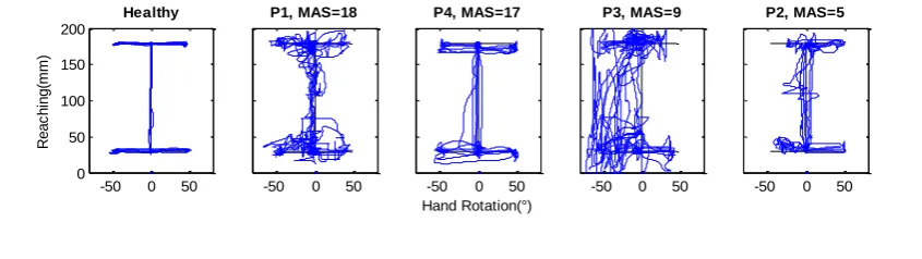
There are evidences which showed that elbow extension angle affects the ROM of hand rotation which are forearm pronation and supination [40]. Besides, the results showed no significant difference between ROM and velocity during performing forearm pronation and supination at two elbow extension angle 135° and 90°. Based on consultation with physiotherapists, to address this effect, the ROM of the target position for all robotic assessment modules was limited to 90° (45° pronation, 45° supination) for elbow flexion angle from 90° to 135° (0 – 150 mm). Moreover, the elbow angle changes during the reaching movement with iRest, therefore, the ROM of this movement in the robotic assessment modules was limited to 150 mm which allows the elbow to extend up to 135°. In addition, based on the hand movement section in Motor Assessment Scale (MAS) score sheet, subjects were required to pick up a polystyrene cup which has a diameter of approximately 60 mm from the table and put it on the table across the other side of their body. The ROM for hand opening task was set at 60 mm (perpendicular distance between thumbs to moving fixture of the grasping mechanism). The tolerances were set to ±3 mm for reaching, ±2° for forearm pronation/supination task and ±2 mm for grasping task. All the modules were performed similarly, where the subject had to move the handle to a target position within time allowance (Draw I, 10s; Draw Diamond and Draw Circle, 20s) and stays at the position for 0.5 seconds for a new target position to be appeared. If the subject failed to reach the target within the time allowance, new target would appear. Figure 3 shows the hand paths covered by a healthy subject and four stroke patients, the data is not discussed in this paper.
-50 0 50
0 50 100 150 200
Healthy
R
e
a
c
h
in
g
(m
m
)
-50 0 50
P1, MAS=18
-50 0 50
P4, MAS=17
Hand Rotation(°)
-50 0 50
P3, MAS=9
-50 0 50
Figure 3. Hand paths covered by a healthy subject and four stroke patients (Healthy, P1, P2, P3 and P4) with different MAS, for the three robotic assessment modules
5. Performance
Fourteen stroke patients with MAS score for upper arm function section at least 3 participated in our studied. The data will be recorded once the game started. Position, time, and number of success target reach will be recorded. Several kinematic variables such as Movement Time (MT), Reaction Time (RT), Stability Time (ST), Mean Velocity (MV), Peak Velocity (PV), Time to PV (TPV), Hit Wall Score (HWS) when the green dot go beyond the white path, Path Ratio (PR), Trajectory Error (TE), Target Reached (TR), Grasping Range of motion and Smoothness were extracted from the recorded data. Our previous study explain in details about the kinematic variables [37].
The extracted data were analysed using multiple linear regression method. Zariffa et. al. [14] suggests four kinematic variables were high enough to produce a regression model with good performance. Therefore the best four combination of the kinematic variables were selected using leave one out cross validation (LOOCV). The combination that produced the minimum root mean square error of LOOCV (RMSEcv) was selected using an exhaustive search of all possible combinations. Then, holdout validation method was used to split the data into training and validation data sets. Least squares error multiple linear regression models was computed for each robotic assessment module outcome using the 4 variables selected in the LOOCV process, and the training data set from the holdout validation method. Then, a model was generated for each robotic assessment module and the prediction quality for each model was evaluated using the following metrics: (i) The value of the Pearson's linear correlation coefficient or correlation coefficient, R. This value is a dimensionless index that measures the degrees to two variables that vary together in a range between -1 and +1 [41] and (ii) the value of root mean square error of training (RMSEt) and root mean square error of validation (RMSEv) of training and validation data sets were computed to investigate the predictive ability models. Table 2 shows the four combinations of the kinematic variables in predicting the MAS score during LOOCV for all robotic assessment modules. The minimum RMSEcv value was 2.12 for Draw I module with a combination of Smoothness, Grasping, Hit wall score and Target reached kinematic variables, 3.02 for Draw Diamond module with a combination of Movement Time, Reaction Time, Path Ratio and Smoothness kinematic variables, and 2.79 for Draw Circle module with a combination of stability time, Movement Time, Reaction Time and Smoothness kinematic variables.
Table 2. RMSEcv values for four combinations of kinematic variables for all modules during LOOCV
Robotic Assessment Draw I Draw Diamond Draw Circle
-50 0 50
0 50 100 150 200
Healthy
R
e
a
c
h
in
g
(m
m
)
-50 0 50
P1, MAS=18
-50 0 50
P4, MAS=17
Hand Rotation(°)
-50 0 50
P3, MAS=9
-50 0 50
P2, MAS=5
-50 0 50 0
50 100 150 200
Healthy
R
e
a
c
h
in
g
(m
m
)
-50 0 50
P1, MAS=18
-50 0 50
P4, MAS=17
Hand Rotation(°)
-50 0 50
P3, MAS=9
-50 0 50
Modules
RMSEcv 2.12 3.02 2.79
Kinematic variables
Smoothness, Grasping, Hit Wall Score and
Target Reached
Movement Time, Reaction Time, Path Ratio and
Smoothness
Stability Time, Movement Time, Reaction Time and
Smoothness
Performance of the prediction models to predict the MAS generated using four kinematic variables selected in the LOOCV process are shown in Table 3. Draw I model shows the highest correlation between kinematic variables and MAS score in training (Rt = 0.84) and validation (Rv = 0.81) data sets than Draw Diamond model (Rt = 0.63 for training and Rv = 0.70 for validation) and Draw Circle model (Rt = 0.71 for training and Rv = 0.64 for validation). Besides, the Draw I model also shows the lowest RMSE in training (RMSEt = 1.85) and validation (RMSEv = 2.05) data sets, denoting higher accuracy compared to Draw Diamond model (RMSEt = 2.68 for training and RMSEv = 2.76 for validation) and Draw Circle model (RMSEt = 2.44 for training and RMSEv = 2.71 for validation).
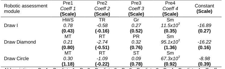
Table 4 provides the movement descriptors used for the predictions and the corresponding coefficients. The Grasping variable provided the largest contribution in Draw I regression model, Movement Time variable provided largest contribution in the Draw Diamond regression model while movement time provided largest contribution in the Draw Circle model. Target reached gave the smallest contribution in Draw I regression model while reaction time gave the smallest contribution in both Draw Diamond and Draw Circle regression models. Even though the target reached and the reaction time were the smallest contributions in prediction models, removing them would cause the model's accuracy (RMSEv) to reduce by more than 3%.
Table 3. Performance of the regression model
Data set Correlation coefficient RMSE Outcome Training Validation Rt Rv RMSEt RMSEv
Draw I 28 14 0.84 0.81 1.85 2.05
Draw Diamond 28 14 0.63 0.70 2.68 2.76
Draw Circle 28 14 0.71 0.64 2.44 2.71
Abbreviations: RMSEt, root mean square error training; RMSEv ,root mean square error validation; Rt, correlation coefficient in the training data set; Rv, correlation coefficient in the validation data set.
Table 4. Regression models for MAS outcome: Outcome = (Predictor1 x Coeff1) + (Predictor2 x Coeff2) + (Predictor3 x Coeff3) + (Predictor4 x Coeff4) + Constant
Robotic assessment module Pre1 Coeff 1 (Scale) Pre2 Coeff 2 (Scale) Pre3 Coeff 3 (Scale) Pre4 Coeff 4 (Scale) Constant (Scale) Draw I HWS 0.78 (0.43) TR -0.58 (-0.16) Gr 0.27 (0.52) Sm 11.5x10³ (0.35) -16.89 (0.27) Draw Diamond MT 0.21 (0.80) RT -2.74 (-0.51) PR 0.32 (0.76) Sm 95.1x10³ (1.36) -16.22 (0.16) Draw Circle MT 0.30 (1.18) RT -1.09 (-0.22) ST 0.09 (0.78) Sm 67.3x10³ (0.92) -8.98 (0.39) Abbreviations: Pre1, Predictor1; Pre2, Predictor2; Pre3, Predictor3; Pre4, Predictor4; Coeff, Coefficient; HWS, Hit Wall Score; TR, Target Reached; Gr, Grasping; Sm, Smoothness; MT, Movement Time;, RT, Reaction Time; PR, Path Ratio; ST, Stability Time.
combining the reaching, hand rotation and grasping movements during the assessment process, it could provide higher correlation between clinical scale and kinematic variables.
In order to reduce the assessment time, the Draw Diamond and Draw Circle modules could be discarded from the task. It is because, these modules showed weak performance in predicting the MAS score, which suggested that these modules did not provide meaningful information to assess hand function. By reducing the robotic assessment module to only Draw I module, it also reduces the number of exercises to be performed and evaluated, potentially simplifying patient evaluation and thus, reduce assessment time.
Before Draw I module can be used for assessment purposes, the correlations between MAS score and kinematic variables must be further increased. To do so, further studies must be conducted. On the other hand, with the current level of Draw I model performance, quantitative data from iRest could potentially be used for interim assessments, assuming that MAS was judged to be appropriate outcomes for the study.
6. Conclusion
The combination of three basic movements which are reaching, hand rotation and grasping in the device to assess the stroke patients provide better correlation in predicting the clinical assessment score compared to the devices that only allowed one or two of the movements. Besides, this study was able to show that a non-motorized device can provide inexpensive and practical way of conducting correlated assessments. The absence of actuation in the device could increase the safety, reduce the complexity of mechanical design and increase usage due to less supervision. The finding shows that the combination of the three basic movements and the unactuated device which allowed voluntary movement from the patient are the important parameter to be implemented in the objective assessment device.
Acknowledgement
The authors would like to thank the physiotherapists from National Stroke Association of Malaysia (NASAM) for providing valuable feedback and recommendation in this project and also to Ministry of Education Malaysia (MOE), Universiti Teknologi Malaysia (UTM) and Universiti Tun Hussein Onn Malaysia (UTHM) for their supports. This work is supported by university research grant [06H86, 08H77], Lab2Market commercialization grant [08906] and Collaborative Research in Engineering, Science and Teknologi Center (CREST) R&D grant [P37C2-13].
References
[1] Casadio M, Giannoni P, Morasso P, Sanguineti V. A proof of concept study for the integration of robot therapy with physiotherapy in the treatment of stroke patients. Clinical rehabilitation. 2009; 23(3): 217-228.
[2] Reinkensmeyer DJ, Galvez JA, Marchal L, Wolbrecht ET, Bobrow JE. Some key problems for robot-assisted movement therapy research: a perspective from the University of California at Irvine. Rehabilitation Robotics. 2007. ICORR 2007. IEEE 10th International Conference on. 2007: 1009-1015.
[3] Colombo R, Pisano F, Micera S, Mazzone A, Delconte C, Carrozza MC, et al. Robotic techniques for upper limb evaluation and rehabilitation of stroke patients. Neural Systems and Rehabilitation Engineering, IEEE Transactions on. 2005; 13(3): 311-324.
[4] Metzger JC, Lambercy O, Chapuis D, Gassert R. Design and characterization of the ReHapticKnob, a robot for assessment and therapy of hand function. Intelligent Robots and Systems (IROS), 2011 IEEE/RSJ International Conference on. 2011: 3074-3080.
[5] Hesse S, Schmidt H, Werner C, Bardeleben A. Upper and lower extremity robotic devices for rehabilitation and for studying motor control. Current opinion in neurology. 2003; 16(6): 705-710. [6] Lambercy O, Dovat L, Gassert R, Burdet E, Teo CL, Milner T. A haptic knob for rehabilitation of hand
function. Neural Systems and Rehabilitation Engineering, IEEE Transactions on. 2007; 15(3): 356-366.
[8] Burke JW, McNeill M, Charles D, Morrow PJ, Crosbie J, McDonough S. Augmented reality games for upper-limb stroke rehabilitation. Games and Virtual Worlds for Serious Applications (VS-GAMES), 2010 Second International Conference on. 2010: 75-78.
[9] Sivak M, Unluhisarcikli O, Weinberg B, Mirelman-Harari A, Bonato P, Mavroidis C. Haptic system for hand rehabilitation integrating an interactive game with an advanced robotic device. Haptics Symposium, 2010 IEEE. 2010: 475-481.
[10] Wong CK, Jordan K, and King M. Robotic arm skate for stroke rehabilitation. Rehabilitation Robotics (ICORR), 2011 IEEE International Conference on. 2011: 1-6.
[11] de los Reyes GA, Dimbwadyo TI, Trincado AF, Monasterio HF, Torricelli D, Gil-Agudo A. Quantitative assessment based on kinematic measures of functional impairments during upper extremity movements: A review. Clinical Biomechanics. 2014; 29(7): 719-727.
[12] Lambercy O, Dovat L, Yun H, Wee SK, Kuah C, Chua K, et al.Robotic assessment of hand function with the HapticKnob. Proceedings of the 4th International Convention on Rehabilitation Engineering & Assistive Technology. 2010: 33.
[13] Krebs H, Volpe B, Ferraro M, Fasoli S, Palazzolo J, Rohrer B, et al. Robot-aided neurorehabilitation: from evidence-based to science-based rehabilitation. Topics in stroke Rehabilitation. 2002; 8(4): 54-70.
[14] Zariffa J, Kapadia N, Kramer JL, Taylor P, Alizadeh-Meghrazi M, Zivanovic V, et al. Relationship between clinical assessments of function and measurements from an upper-limb robotic rehabilitation device in cervical spinal cord injury. Neural Systems and Rehabilitation Engineering, IEEE Transactions on. 2012; 20(3): 341-350.
[15] Bosecker C, Dipietro L, Volpe B, Krebs HI. Kinematic robot-based evaluation scales and clinical counterparts to measure upper limb motor performance in patients with chronic stroke.
Neurorehabilitation and neural repair. 2010; 24(1): 62-69.
[16] Gijbels D, Lamers I, Kerkhofs L, Alders G, Knippenberg E, Feys P. The Armeo Spring as training tool to improve upper limb functionality in multiple sclerosis: a pilot study. Journal of neuroengineering and rehabilitation. 2011; 8(5): 5.
[17] Celik O, O'Malley MK, Boake C, Levin HS, Yozbatiran N, Reistetter TA. Normalized movement quality measures for therapeutic robots strongly correlate with clinical motor impairment measures.
Neural Systems and Rehabilitation Engineering, IEEE Transactions on. 2010; 18(4): 433-444. [18] Rohafza M, Fluet G, Qiu Q, and Adamovich S. Correlations between statistical models of robotically
collected kinematics and clinical measures of upper extremity function. Engineering in Medicine and Biology Society (EMBC), 2012 Annual International Conference of the IEEE. 2012: 4120-4123. [19] Murphy MA, Willén C, Sunnerhagen KS. Movement kinematics during a drinking task are associated
with the activity capacity level after stroke. Neurorehabilitation and neural repair. 2012; 26(9): 1106-1115.
[20] Chang JJ, Yang YS, Wu WL, Guo LY, Su FC. The constructs of kinematic measures for reaching performance in stroke patients. Journal of Medical and Biological Engineering. 2008; 28(2): 65-70. [21] Bonato P. Wearable sensors/systems and their impact on biomedical engineering. IEEE Engineering
in Medicine and Biology Magazine. 2003; 22(3): 18-20.
[22] Bonato P. Advances in wearable technology for rehabilitation. Stud Health Technol Inform. 2009; 145: 145-159.
[23] Bonato P. Advances in wearable technology and applications in physical medicine and rehabilitation.
Journal of Neuro Engineering and Rehabilitation. 2005; 2(1): 2.
[24] Hester T, Hughes R, Sherrill DM, Knorr B, Akay M, Stein J, et al.Using wearable sensors to measure motor abilities following stroke. Wearable and Implantable Body Sensor Networks, 2006. BSN 2006. International Workshop on. 2006; 4: 8.
[25] Patel S, Hughes R, Hester T, Stein J, Akay M, Dy JG, et al. A novel approach to monitor rehabilitation outcomes in stroke survivors using wearable technology. Proceedings of the IEEE. 2010; 98(3): 450-461.
[26] Del Din S, Patel S, Cobelli C, Bonato P. Estimating fugl-meyer clinical scores in stroke survivors using wearable sensors. Engineering in Medicine and Biology Society, EMBC, 2011 Annual International Conference of the IEEE. 2011: 5839-5842.
[27] Murphy MA, Willén C, Sunnerhagen KS. Kinematic variables quantifying upper-extremity performance after stroke during reaching and drinking from a glass. Neurorehabilitation and neural repair. 2011; 25(1): 71-80.
[28] Reinkensmeyer DJ, Boninger ML. Technologies and combination therapies for enhancing movement training for people with a disability. J Neuroeng Rehabil. 2012; 9(17).
[29] Yeong CF, Melendez-Calderon A, Burdet E. Analysis of pick-and-place, eating and drinking movements for the workspace definition of simple robotic devices. Rehabilitation Robotics, 2009. ICORR 2009. IEEE International Conference on. 2009: 46-52.
[30] Morasso P. Spatial control of arm movements. Experimental brain research. 1981; 42(2): 223-227. [31] Riemann BL, Lephart SM. The sensorimotor system, part I: the physiologic basis of functional joint
[32] Cho HY, Kim JS, Lee GC. Effects of motor imagery training on balance and gait abilities in post-stroke patients: a randomized controlled trial. Clinical rehabilitation. 2013; 27(8): 675-680.
[33] Kim SI, Song IH, Cho S, Kim IY, Ku J, Kang YJ, et al.Proprioception rehabilitation training system for stroke patients using virtual reality technology. Engineering in Medicine and Biology Society (EMBC), 2013 35th Annual International Conference of the IEEE. 2013: 4621-4624.
[34] Murphy MA, Sunnerhagen KS, Johnels B, Willén C. Three-dimensional kinematic motion analysis of a daily activity drinking from a glass: a pilot study. Journal of neuroengineering and rehabilitation. 2006; 3(1): 18.
[35] Yeong CF, Melendez-Calderon A, Gassert R, Burdet E. ReachMAN: a personal robot to train reaching and manipulation. Intelligent Robots and Systems, 2009. IROS 2009. IEEE/RSJ International Conference on. 2009: 4080-4085.
[36] Lindgren I, Jönsson A-C, Norrving B, Lindgren A. Shoulder pain after stroke A prospective population-based study. Stroke. 2007; 38(2): 343-348.
[37] Abdul RH, Khor KX, Yeong CF, Su ELM, Narayanan ALT. The potential of iRest in measuring the hand function performance of stroke patients. Bio-Medical Materials and Engineering. 2017; 28(2): 105-116.
[38] Rahman HA, Narayanan ALT, Xiang KK, Ming ESL, Fai YC, Khan QI. iRest: Interactive rehabilitation and assessment tool. Control Conference (ASCC), 2015 10th Asian. 2015: 1-6.
[39] Rahman HA, Xiang KK, Fai YC, Ming ESL, Narayanan ALT. Robotic Assessment Modules for Upper Limb Stroke Assessment: Preliminary Study. Journal of Medical Imaging and Health Informatics. 2016; 6(1): 157-162.
[40] Rahman HA, Fai YC, Ming ESL. Analysis of Human Hand Kinematics: Forearm Pronation and Supination. Journal of Medical Imaging and Health Informatics. 2014; 4(2): 245-249.
[41] Lee Rodgers J, Nicewander WA. Thirteen ways to look at the correlation coefficient. The American Statistician. 1988; 42(1): 59-66.
[42] Colombo R, Pisano F, Micera S, Mazzone A, Delconte C, Carrozza M, et al. Assessing mechanisms of recovery during robot-aided neurorehabilitation of the upper limb. Neurorehabilitation and neural repair. 2008; 22(1): 50-63.