18th International Conference on Structural Mechanics in Reactor Technology (SMiRT 18) Beijing, China, August 7-12, 2005 SMiRT18-G06-4
FAD-BASED DEFECT ASSESSMENT METHOD FOR WELDED
STRUCTURES AT HIGH TEMPERATURE
Fuzhen Xuan, Shantung Tu, Zhengdong Wang
Scholl of Mechanical Engineering, East China University of Science and Technology
Phone: 86-21-64253513, Fax: 86-21-64253425
E-mail: [email protected]
ABSTRACT
To evaluate the safety of welded structures operated at elevated temperature, a R6 type failure assessment diagram (FAD) method has been developed in the present work. When crack located in a weld, the mismatch effect in creep properties need be addressed. To include such an effect, a weighted average method for both over- and under-matching of creep performance of the weld and base materials is presented and an equivalent isochronous stress-strain curve (EISSC) is then defined. Accordingly a time dependent failure assessment curve is constructed using the method of R6 Option 2. The application of such an approach to an internal circumferentially defected welded-cylinder under axial tension has been studied. Results indicate that, the dependence of modified time-dependent failure assessment curves (TDFACs) on geometry, crack size and service time is not large and nearly collapsed into one curve.
Keywords: failure assessment diagram; welded structures; defect assessment; high temperature.
1. INTRODUCTION
In recent years, a number of attempts have been made to describe the creep crack initiation (CCI) and creep crack growth (CCG) performance in weldments, especially in the mismatched welds (Dogan and Petrovski, 2001; Budden and Curbishley, 2000; Assire et al, 2001; Segle et al, 2000; Yoon and Kim, 1999; Tu and Yoon, 1999; Xuan et al, 2004). Almost all previous work are concentrated on the high temperature fracture parameter calculation and the creep crack growth description. The finite element method and creep crack growth test are unexceptionally employed. Undoubtedly, these research results are imperative and necessary for the welded structural integrity assessment at high temperature. However, it should be also attractive to develop a simplified and convenient method for high temperature defects assessment of mismatched welded structures, following the idea of R6 failure assessment diagram (FAD) approach for ambient temperature cases (R6, 2000).
procedures (Kim et al, 2000). In consideration of the analogy between plasticity and creep as well as the definitions of J and C*, it is expected to develop a FAD-based method to accommodate the high temperature crack assessment in weldments on the basis of the ‘equivalent material’ concept.
In this paper, an equivalent isochronous stress-strain relationship (EISSR) is first proposed by treating the mismatched weldment as fictitious equivalent material and then used to modify the current TDFAD approach. Employing the TDFAD, together with the limit load solution of the mismatched weld, it is shown that the integrity assessment of a cracked weld at high temperature can be performed by following the FAD-based procedure.
2. DEFINITION OF AN EQUIVALENT ISOCHRONOUS STRESS- STRAIN RELATIONSHIP
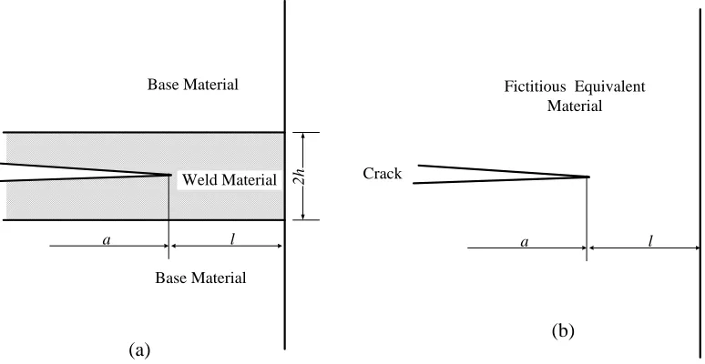
Consider a crack located in a weld with a mismatch in creep properties from the surrounding base metal, it is usually simplified as an idealized bi-material ‘sandwich’ structure without HAZ and residual stress, as shown in Fig. 1(a). In elastic-plastic regime, this problem in R6 and SINTAP procedures is treated as an equivalent homogeneous material with the same configuration as shown in Fig. 1(b), which follows the constitutive equation
) 1 (
) ( ) / (
) ( ) 1 /
( )
( p Lmis Lb w p Lmis Lb b p
eq
− − + −
=
M
F F M F
F
σ
ε
σ
ε
ε
σ
(1)where FLmis represents the limit load for the mismatched weld; FLb is the limit load of the cracked
homogeneous structure for base metal corresponds to the 0.2% proof stress ratio; σb(εp) and σw(ε p)
are the stress-plastic strain relationship of base metal and of the weld metal, respectively; M denotes the mismatch ratio defined at a number of plastic strain values, M=σw(εp)/σ b(εp). For εp = 0.2%, M
corresponds to the 0.2% proof stress ratio.
Weld Material Base Material
Base Material
a l
2h Crack
Fictitious Equivalent Material
a l
(b) (a)
Fig.1. The ‘sandwich’ model of a cracked mismatched bi-material weld and fictitious
equivalent material
From the phenomenological point of view, no difference exists between plasticity and creep in metal and both of them are often classified as the inelastic strains. In terms of different causes of deformation, total strain of the metal at high temperature can be split into three components: elastic strain, creep strain and plastic strain and can be expressed by
ine c p
e
(
)
[
(
)
(
)]
)
,
(
σ
ε
σ
ε
σ
ε
σ
ε
t
=
+
+
(2) where εe(σ), εp(σ) and εc(σ) is the elastic strain, plastic strain and creep strain, respectively.deformation causes, the equivalent relationship described by Eq. (1) should hold for all the inelastic strains. In this instance, the constitutive equation for the fictitious equivalent material is
)
1
(
)
(
)
/
(
)
(
)
1
/
(
)
(
Lmis Lb w ine Lmis Lb b ineine eq
−
−
+
−
=
M
F
F
M
F
F
σ
ε
σ
ε
ε
σ
(3)Under the condition of long term creep state, the total strain of equation (1) is dominated by creep component and thus plastic strain component is negligible. For both base and weld materials obeying the elastic-power creep law, the inelastic strain in both materials is expressed by
t B nb
b b c
ine
ε
(σ
)σ
ε
= = (4) tB nw
w w c
ine
ε
(σ
)σ
ε
= = (5) where B b, n b and B w, n w are respectively the material constants in Norton’s creep law for base andweld metals; t denotes the service time.
In terms of Eqs (4) and (5), the mismatch ratio M can be calculated by the following formulation for high temperature application
(
)
w bw b
w
b 1/
b / 1 w
ine/ ( ) ( )
n n n n n n B B t M − −
=
ε
(6) Equation (6) indicates that the mismatch ratio M is a time dependent function at high temperature. For most metals used in high temperature structures, however, no clearly difference exists at the values of creep exponent n and thus the value of nb- nw /(nbnw) closes to nil, which indicates that the mismatchratio M is insensitive to time and can be approximated as a time-independent function of material constants in practice.
Substitute Eqs (4) and (5) into Eq. (3), the equivalent stress-creep strain relationship for the mismatched weld is then obtained
−
−
+
−
−
=
1
1
/
1
/
1/ Lmis Lbw c Lb Lmis / 1 b c eq w b
M
F
F
t
B
M
F
F
M
t
B
n nε
ε
σ
(7)In conventional TDFAD, a parameter, σ0.2 c
, so-called 0.2% proof stress corresponding to 0.2% inelastic strain from the isochronous curve of homogeneous material, should be defined (Ainsworth et al, 1999). For the mismatched case, an equivalent 0.2% proof stress, σ0.2e
c
, is defined
c b 2 . 0 Lb Lmis c 0.2w Lw Lmis c
0.2e
σ
σ
σ
F
F
F
F
=
=
(8)For the assessment time and temperature of interest, the stress to cause creep rupture is also required. Similarly, an equivalent rupture stress for the mismatched weldment, σre, can be evaluated from the
corresponding creep rupture data of base metal and weld metal using
)]
(
),
(
min[
rw rbre
σ
t
σ
t
σ
=
(9) where σrb(t) and σrw(t) denote the creep rupture stress of base material and weld materialcorresponding to time of interest, respectively. It should be noted that the definition of equivalent rupture stress is arbitrary but a safe choice for the definition of cut-off Lr
max
in TDFAD is the mean of yield and rupture stress.
The equivalent isochronous stress-creep strain relationship obtained from equation (7) can be expressed in the inverse form
)
(
eqc
c
ε
σ
ε
=
(10) Under the condition of long term creep state, the equivalent isochronous stress-strain relationship can be obtained straightforwardly by adding the elastic strain to equation (10))
(
/
)
(
σ
eqσ
eε
cσ
eqε
=
E
+
(11) where E denotes Young’s modulus.According to the prescription in R5 appendix (2003), the TDFAD approach assesses creep fracture by evaluating two normalized parameters, Kr and Lr, and comparing the position of the point (Lr, Kr)
with the time-dependent failure assessment curve (TDFAC), and a cut-off at Lr=Lr max
. The TDFAC covers small scale creep crack growth, where Lr<1 and f(Lr)→1, and widespread creep regime, where f(Lr)<1, and the cut-off corresponds to creep rupture. In this section, the parameters Lr, Kr, f(Lr) and Lr
max
are defined for the case of a defect in a weld with a mismatch in creep properties between the base metal and weld metal.
3.1 Definition of Lr
Referring to the modification of traditional FAD for mismatched welded structures by Lei and Ainsworth (1996), it is proposed that the abscissa of the TDFAD at elevated temperature is defined as
Lmis
r
F
/
F
L
=
(12) where F is applied load. This differs from the conventional definition of Lr in TDFAD in using themismatch limit load, FLmis. If Lr is defined using the limit load assuming the structure is homogeneous
and made of the weakest material in the weldment then larger values of Lr than those evaluated from
equation (12) are produced. In view of equation (8), the use of equation (12) reduced Lr by the ratio of
the 0.2% proof stress of the weakest material to the 0.2% proof stress of the equivalent material.
3.2 Definition of TDFAC
Following the definition of time-dependent failure assessment curve in conventional TDFAD, it is proposed that the TDFAC for defect assessments for mismatched welds is defined by:
2 / 1
ref c 0.2 3 r c 0.2 r
ref r
2
)
(
−
+
=
ε
σ
σ
ε
E
L
L
E
L
f
whenL
r≤
L
maxr (13)0 )
(Lr =
f when
L
r>
L
maxr (14) whereε
ref is the total strain corresponding to the reference stress from the effective isochronousstress-strain curve at the specific time and temperature. It is noted that the option 2 curve in R6 is often not very sensitive to the detailed shape of the stress-strain curve and this has lead to a simplified Option 1 curve in R6 which is independent of material properties. For creep assessment, the dependence of failure assessment curves on time is not large according to Ainsworth’s results (1993) and it is expected to develop an alternative to Option 1 curve in R6. This is discussed further later in the context of the following section.
3.3 The cut-off Lr max
The proposed definition of cut-off for welded structure is identical with the calculation of parameter used in TDFAD for homogeneous structures. To be consistent with the R6 procedure and insure that not exceed the value of R6 FAD, is defined as follows
max r
L
L
maxrmax r
L
L
maxrc 0.2e T fe max
r
=
σ
/
σ
L
(15)where is taken as the ratio of effective high temperature flow stress, , to proof stress,
. Being similar to the definition of flow stress in R6 procedure, the effective high temperature
flow stress is arbitrary and defined as , where
max r
L
σ
feTc 2 . 0 e
σ
2
/
)
(
re 0.2ec Tfe
σ
σ
σ
=
+
σ
re is the stress to cause creeprupture at the same time as is evaluated. If exceeds , failure is expected to occur due to creep rupture, rather than fracture. It is apparent that the use of a high temperature flow stress is consistent with R6 at short time.
c 2 . 0 e
4. APPLICATION OF THE MODIFIED TDFAD TO WELDED JOINTS IN CYLINDERS To further expound the application of above
described method in engineering, in this section, such a method is applied to assess an idealized cracked welded joint in cylinders with a mismatch in creep properties between the base and weld materials. A pipe with an internal fully circumferential defect in the center line of an idealized weld under axial tension is considered. The geometry of the pipe is shown in Fig. 2.
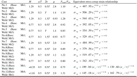
Four materials, denoted Mt1 to Mt4 in Table 1, with different creep coefficients and creep exponents have been chosen. The data of Mt1 and Mt4 are respectively those of 1Cr0.5Mo and 1.25Cr0.5Mo from the work of Yoon and Kim (1999). The other two materials are idealized to produce a range of stress-creep strain response. Twelve different mismatching cases with different ratios of the crack depth to the thickness of the pipe have been assessed. The
various combinations considered are summarized in Table 2.
Ri Ro F F Base metal Base metal 2 h Weld a
Fig. 2 Thin-walled cylinder with fully
circumferential crack in the weld centre under
tension
Table 1 Mechanical property utilized in the pipe under axial tension
Materials Stress-strain relationship Elastic modulus
E(MPa) B (MPa
-n
h-1) n
Mt1 Elastic-viscosity 175E3 1.83E-24 9.03
Mt2 Elastic-viscosity 175E3 1.83E-25 9.03
Mt3 Elastic-viscosity 175E3 1.83E-23 9.03
Mt4 Elastic-viscosity 175E3 6.36E-23 9.36
Table 2 Cases assessed for the pipe with mismatched weld joint under axial tension
Case M a/T 2h ψ FLmis/FLb Equivalent stress-creep strain relationshipNo.1 (Base: Mt1;
Weld: Mt2) 1.29 0.3 0.5T 2.8 1.10
03 . 9 / 1 1/9.03 c eq 467.95
−
= ε t
σ
No.2 (Base: Mt1;
Weld: Mt2) 1.29 0.3 T 1.4 1.19
03 . 9 / 1 1/9.03 c eq 506.29
−
= ε t
σ
No.3 (Base: Mt1;
Weld: Mt2) 1.29 0.3 1.5T 0.93 1.28
03 . 9 / 1 1/9.03 c eq 544.63
−
= ε t
σ
No.4 (Base: Mt1;
Weld: Mt3) 0.77 0.3 0.5T 2.8 0.92
03 . 9 / 1 1/9.03 c eq 392.05
−
= ε t
σ
No.5 (Base: Mt1;
Weld: Mt3) 0.77 0.3 T 1.4 0.83
03 . 9 / 1 1/9.03 c eq 354.59
−
= ε t
σ
No.6(Base: Mt1;
Weld: Mt3) 0.77 0.3 1.5T 0.93 0.77
03 . 9 / 1 1/9.03 c eq 329.61
−
= ε t
σ
No.7 (Base: Mt1;
Weld: Mt2) 1.29 0.5 0.5T 2.0 1.14
03 . 9 / 1 1/9.03 c eq 484.99
−
= ε t
σ
No.8(Base: Mt1;
Weld: Mt3) 0.77 0.5 0.5T 2.0 0.89
03 . 9 / 1 1/9.03 c eq 379.56
−
= ε t
σ
No.9(Base: Mt1;
Weld: Mt2) 1.29 0.7 0.5T 1.2 1.22
03 . 9 / 1 1/9.03 c eq 519.07
−
= ε t
σ
No.10(Base: Mt1;
Weld: Mt3) 0.77 0.7 0.5T 1.2 0.80
03 . 9 / 1 1/9.03 c eq 342.10
−
= ε t
σ
No.11(Base: Mt1;
Weld: Mt4) ≈0.55 0.5 0.5T 2.0 0.75
36 . 9 / 1 c 03 . 9 / 1
c / ) 130 .66( / ) (
04 .
189 t t
eq ε ε
σ = +
No.12(Base: Mt4;
Weld: Mt1) ≈1.81 0.5 0.5T 2.0 1.31
03 . 9 / 1 c 36 . 9 / 1
c / ) 162 .79( / ) (
18 .
145 t t
eq ε ε
4.1 Equivalent isochronous stress-strain curves
For FLmis of cylinder with cracks in mismatched weld of interest herein, a set of solutions have been
provided in R6 procedure (2000). Inserting those limit load solutions into Eq. (7) proposed in this work, the equivalent stress-creep strain relationship for mismatched pipe is then established.
For the under-matching weld the equivalent stress-creep strain relationship for different time is w / 1 w c eq n
t
B
=
ε
σ
0
≤
ψ
≤
1
(16)
−
−
+
−
−
=
1
1
)
,
min(
1
)
,
min(
1/ 1 2w c 2 1 / 1 b c eq w b
M
x
x
t
B
M
x
x
M
t
B
n nε
ε
σ
ψ
>
1
(17)where
x
1=
M
[
1
+
(
ψ
−
1
)
/
3
3
]
, x2 =1−(1−M)/ψ
,ψ
=
(
T
−
a
)
/
h
. T =Ro-Ri is the thickness ofthe pipe, a is the depth of fully circumferential crack, 2h is total width of weld, as shown in Fig.2. For the over-matching weld, M>1, the equivalent stress-creep strain relationship of welded pipe is
−
−
−
+
−
−
−
=
− −1
1
)
)
/
1
(
,
min(
1
)
)
/
1
(
,
min(
1/ 3 1w c 1 3 / 1 b c eq w b
M
T
a
x
t
B
M
T
a
x
M
t
B
n nε
ε
σ
(18)where = ≥ + + = ≤
= −2( −1)/5
1 1 1)/5 --2( 1 3 e for 25 24 ) ( 25 1) -24( e for M M M M M x
ψ
ψ
ψ
ψ
ψ
ψ
0.0 0.2 0.4 0.6 0.8 1.0 1.2 1.4 1.6 1.8 2.0 2.2 0 50 100 150 200 250 300 St re ss σ (MPa )
εc (Creep Strain) Mt1
a/T=0.3, 2h=0.5T, ψ=2.8 a/T=0.5, 2h=0.5T, ψ=2.0 a/T=0.3, 2h=T, ψ=1.4 a/T=0.7, 2h=0.5T, ψ=1.2 a/T=0.3, 2h=1.5T, ψ=0.93 Mt2
(a) M>1, Base metal: Mt1, Weld metal: Mt2
0.0 0.5 1.0 1.5 2.0
0 50 100 150 200 250 Stre s s σ (M P a )
Creep strain εc
Mt1
a/T=0.3, 2h=0.5T, ψ=2.8
a/T=0.5, 2h=0.5T, ψ=2.0
a/T=0.3, 2h=1.0T, ψ=1.4
a/T=0.7, 2h=0.5T, ψ=1.2
a/T=0.3, 2h=1.5T, ψ=0.93
Mt3
(b) M<1, Base metal: Mt1; Weld metal: Mt3
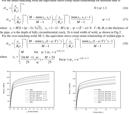
Fig. 3 Comparison between the equivalent stress-creep strain curve and the stress-creep
strain curves of homogeneous specimens for base metal and weld metal (for cylinder at a
given time t= 1000h)
parameter ψ. When the value ofψ decreases, the ESCSR of mismatched welded cylinder closes to the stress-creep strain curve of homogeneous cylinder made of weld metal. While with the value of ψ increasing, the ESCSR gradually closes to the stress-creep strain curve of homogeneous cylinder made of base metal, as seen in Fig. 3 (a) and (b). It is expected according to the above results that as long as the welding seam is wide enough, the weld metal will control the creep resistance of mismatched weld and the influence of base metal can be negligible in this instance.
4.2 Modified time dependent failure assessment diagram
Having determined the equivalent stress-creep strain relationship, it is very easy to obtain the equivalent isochronous stress-strain curve of mismatched welded cylinder by adding the elastic strain to ESCSR. The corresponding equivalent 0.2% proof stress σ0.2e
c
and equivalent creep rupture stress can be determined straightforwardly from Eqs. 8 and 9. The TDFAD is constructed by using the equivalent isochronous stress- strain relationship in Eq. 13 with Lr evaluated from Eq. 12.
The TDFADs for selected cases in Table 2 are shown in Fig. 4(a) to (c). Similar to the equivalent isochronous stress-strain curve (EISSC) being a weight average of isochronous stress-strain curves of base and weld materials, the modified TDFADs constructed from the EISSC and the equivalent 0.2% proof stress lie between the TDFADs of the weld and base materials. For over-matching weldment (M>1), the failure assessment curves always lie over that of evenmatched welded cylinder made of base metal, and for under-matching cases (M<1), the failure curves are always located below that of evenmatched welded cylinder made of base metal. Fig .4 also indicates the influences of combined parameter ψ on the modified TDFAD. When the value ofψ decreases, the TDAFD of mismatched welded cylinder closes to that of homogeneous cylinder made of weld metal. While with the value of ψ increasing, the TDFAD gradually closes to that of homogeneous cylinder made of base metal.
From Fig. 3(a) to (b), the effect of crack and weld width on ESCSR is clear. However, for both over-matching (M>1) and under-matching (M<1) weldments considered herein, the TDFACs from the ESCSRs are nearly collapsed onto one curve (Fig. 4). The scatter of the TDFACs is reasonably small. From this point, it is expected that the use of EISSC with Eq. 13 leads to a general curve similar to Option 1 FAD of R6 procedure if both the weld and base are reasonably described by a TDFAC.
0.0 0.2 0.4 0.6 0.8 1.0 1.2 1.4 1.6
0.0 0.2 0.4 0.6 0.8 1.0
Kr
Lr=F/FLmis
Mt1 a/T=0.3, ψ=2.8 a/T=0.5, ψ=2.0
a/T=0.3, ψ=1.4
a/T=0.7, ψ=1.2 a/T=0.3, ψ=0.93
Mt2
(a) M>1, Base metal: Mt1, Weld metal: Mt2
0.0 0.2 0.4 0.6 0.8 1.0 1.2 1.4 1.6
0.0 0.2 0.4 0.6 0.8 1.0
Kr
Lr=F/FLmis Mt1
a/T=0.3, ψ=2.8
a/T=0.5, ψ=2.0 a/T=0.3, ψ=1.4 a/T=0.7, ψ=1.2
a/T=0.3, ψ=0.93
Mt3
(b) M<1, Base metal: Mt1, Weld metal: Mt3
Fig. 4 Comparison of TDFADs for cylinder with different crack in center of weld and for
0.0 0.2 0.4 0.6 0.8 1.0 1.2 1.4 1.6 0.0
0.2 0.4 0.6 0.8 1.0
Kr
Lr=F/FLmis M=1.29 M=0.77
ψ=2.8 ψ=2.8
ψ=1.2 ψ=1.2
ψ=0.93 ψ=0.93
0.0 0.2 0.4 0.6 0.8 1.0 1.2 1.4 1.6
0.0 0.2 0.4 0.6 0.8 1.0
Kr
Lr=F/FLmis t=102
h
M<1; M>1 t=103h
M<1; M>1 t=104
h
M<1; M>1 t=105h
M<1; M>1
Opt.1 R6 eqn (20)
Fig. 5 Variation of TDFAC with geometry
sizes of weld line for cylinder with crack depth
of a/T=0.3 at time t= 10000h (for M=1.29,
Base metal: Mt1 Weld metal: Mt2; for
M=0.77, Base metal: Mt1 Weld metal: Mt3)
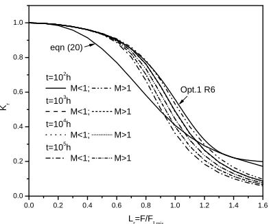
Fig. 6 Variation of TDFAC with service time
for cylinder with a/T=0.5, 2h=0.5T (for M>1,
Base metal : Mt1 Weld metal: Mt2; for M<1,
Base metal : Mt1 Weld metal: Mt3)
For the cases with the same mismatching ratio and crack size, the detailed influences of geometry sizes of weld line on TDFAD are described in Fig.5. In contrast with the EISSCs being obviously affected by the geometry size of weld line and crack, it is worth noting that only slight discrepancy is observed for modified TDFADs of cylinder with same cracks and different width of weld line.
As the equivalent 0.2% proof stress and the isochronous curves are all time dependent, the failure assessment curve is time dependent. The dependence of modified TDFACs on service time is depicted in Fig. 6 for the cylinders with the same geometry and different mismatching ratio M. To make comparisons, the option 1 curve of R6 at ambient temperature:
)] 6 . 0 exp( 7 . 0 3 . 0 [ ] 5 . 0 1 [ )
( 6
r 5
. 0 2 r r
1 L L L
f = + − + − (19) and an alternative to R6 Option 1 curve for creep assessments developed by Ainsworth (1993) based on isochronous data of austenitic steel at 600oC and corresponding to 300, 000 hours are also plotted in Fig. 6, respectively:
)]
4
.
1
exp(
65
.
0
35
.
0
)[
2
.
0
1
(
)
(
r 2r 3rc
L
L
L
f
=
−
+
−
(20) It is clear from Fig. 6 that all time dependent failure assessment curves derived from equivalent isochronous stress-strain data located below the R6 Option 1 curve. At low Lr values, the failureassessment curves for creep assessment are very close to the option1 curve of R6. While at high values of Lr (Lr >0.6), the failure assessment curves fall increasingly below the short-time curve with increase
in time. However, the dependence on time is not large, especially for the values of Lr larger than 1.5. It
is expected that curves at larger times may be used to provide conservative failure assessment diagrams for assessments at shorter times.
Comparing the modified TDFACs of Cr-Mo steel to the conservative failure assessment curve extracted from isochronous data of austenitic steel, it is apparent that the curve of Eq. 20 is over-conservation in the region of Lr=0.4 to 0.8 for Cr-Mo steel structures at shorter time. However,
for the higher levels of Lr, e.g. Lr values is larger than 1.0, the curve of Eq. 20 will lead to
non-conservative results for Cr-Mo steel structures. This indicates the curve of Eq. 20 from isochronous data of austenitic steel is not suitable for the application of Cr-Mo steel.
(1) A weighted average method for isochronous stress-strain curves of base metal and weld metal has been presented. Upon this, an equivalent isochronous stress-strain curve is defined which depends not only on the mechanical properties of both the weld and base materials but also on the geometry and crack size.
(2) On the basis of the equivalent isochronous stress-strain curve, a modified time-dependent failure assessment curve for creep crack assessment of mismatched weldment is constructed using the method of R6 Option 2 method. The related parameters, such as equivalent 0.2% proof stress, equivalent creep rupture stress and the cut-off on TDFAD, have been defined.
(3) The modified TDFAD method has been applied to an internal fully circumferential defected welded cylinder under axial tension. Study shows that, for over-matching weldment (M>1), the modified TDFADs constructed from the EISSC always lie over that of even-matched welded cylinder made of base metal, and for under-matching cases (M<1), the failure curves are always located below that of even-matched welded cylinder made of base metal.
(4) The dependence of modified TDFACs on geometry, crack size and service time is not large and nearly collapsed onto one curve. It is expected that curves at larger times may be used to provide conservative failure assessment diagrams for assessments at shorter times. However, the general failure assessment curve from isochronous data of austenitic steel is non conservative for some cases and thus not applicable for Cr-Mo steel.
ACKNOWLEDGMENTS
The supports provided by China Natural Science Foundation (contract No. 50225517 and 10172046) and the Natural Science Foundation of Shanghai (contract No. 03ZR14022) are gratefully acknowledged.
REFERENCES
1 Dogan, B. and Petrovski, B. (2001). Creep crack growth of high temperature weldments. International
Journal Pressure Vessel & Piping78, 795-805.
2 Budden, P.J. and Curbishley, I. (2000). Assessment of creep crack growth in dissimilar metal welds,
Nuclear Engineering and Design197, 13-23.
3 Assire, A., Michel, B. and Raous, M. (2001). Creep crack initiation and creep crack growth assessments in
welded structures, Nuclear Engineering and Design206, 45-56.
4 Segle, P., Andersson, P. and Samuelson, L.A. (2000). Numerical investigation of creep crack growth in cross-weld CT specimens. Part I: influence of mismatch in creep deformation properties and notch tip
location, Fatigue and Fracture of Engineering Materials & Structures23, 521-531.
5 Yoon, K.B. and Kim, K.Y. (1999). High temperature fracture parameter for a weld interface crack,
Theoretical and Applied Fracture Mechanics32, 27-35.
6 Tu, S.T. and Yoon, K.B. (1999). The influence of material mismatch on the evaluation of time-dependent
fracture mechanics parameters, Engineering Fracture Mechanics64, 765-780.
7 Xuan FZ, Tu ST, Wang ZD. (2004). C* estimation for cracks in mismatched welds and finite element
validation, International Journal of Fracture. 126(3): 267-280
8 R6. (2000). Assessment of the integrity of structures containing defects, Procedure R6-Revision 4, Gloucester, UK: Nuclear Electric Ltd.
9 Ainsworth RA, Hooton DG, Green G. (1999). Failure assessment diagrams for high temperature defect
assessment, Engineering Fracture Mechanics, 62(1): 95-109
10 Ainsworth RA. (1993). The use of a failure assessment diagram for initiation and propagation of defects
at high temperatures, Fatigue Fracture Engng Mater Struct, 16: 1091-1108
11 R5. (2003). Assessment procedure for the high temperature response of structures. British Energy Generation Ltd, Revision-2003.
12 Lei Y, Ainsworth RA. (1996).Failure assessment diagram for cracks in welds with mismatched
mechanical properties, ASME PVP Fatigue and Fracture, 324: 65-73.
13 Kim, Y.-J., Kocak, M., Ainsworth, R.A. and Zerbst, U. (2000). SINTAP defect assessment procedure for