Multi Rate Filter Bank Using MSFT Filter for
Digital Hearing Aid
Nisha S. Rani1, Sreejesh Kumar R2
PG Scholar, Dept. of ECE, TKM Institute of Technology, Kollam, Kerala, India1
Asst. Professor, Dept. of ECE, TKM Institute of Technology, Kollam, Kerala, India2
ABSTRACT: Variable Finite Impulse Response (FIR) filters are useful in wireless communications, adaptive systems, audio signal processing, and biomedical applications etc. While considering the design of a digital hearing aid variable digital filters plays an important role. The existing methods for the filter design have some drawback in terms of area, delay and other characteristics. So that a multi rate filter bank using Modified Second order Frequency Transform (MSFT) filter is introduced which replace ordinary FIR filters with MSFT filters. In the modified second order frequency transformation filter, a novel idea of relaxing the one-to-one mapping condition between the frequency variables is adopted along with low pass to high pass transformation, which gives a better performance compared to other filtering methods. To validate the design, input is extracted with the help of MATLAB R2010a, codes can be developed using Verilog HDL in Xilinx ISE Design Suite 14.2 and to be simulated in ISimISE O.61xd Simulator
.
KEYWORDS: Finite impulse response (FIR) filter; frequency transformations; variable linear-phase digital filter.
I. INTRODUCTION
In many signal processing applications a clear need to change the parameters of the filters used exists. Such applications are found in telecommunications, digital audio equipment, medical electronics, radar, sonar and control systems, adaptive and tracking systems, spectrum and vibration analyses, for many speech synthesizers and in numerous laboratory instruments. The most general term for filters with changeable parameters is variable filters, but they are often called tuneable or programmable. So that variable digital filters are made popular. Variable Finite Impulse Response (FIR) filters (FIR filters whose frequency response can be changed based on the desired specifications) are widely used in digital communications. The frequency response of an FIR filter can be changed by completely changing its coefficients or by modifying the impulse response using various operations. In the programmable digital filters, the desired frequency responses are obtained by updating all the filter coefficients which are stored in the memory. This is a very simple approach, and in general, the variable coefficient filters are optimum in a sense that the filter length for the particular frequency response specifications is the minimum. Changing parameters leads to control over the various characteristics of FIR filters which improves the performance. There are several methods adopted for such design. The technique includes interpolation approach, Spectral Parameter Approximation (SPA) technique, transformation etc.In the interpolation approach, each delay of the fixed-coefficient filter structure is replaced by M delays to obtain a multiband response and then the desired band is extracted using a masking filter. In the Coefficient Decimation Method (CDM), the impulse response of the fixed-coefficient filter is modified by retaining everyDth coefficient of the filter and either replacing the remaining coefficients by zeros or by completely discarding them. Even though the interpolation and CDM techniques are simple to implement and low complexities, they provide only coarse control over the cut-off frequency due to the discrete nature of the controlling parameters.
So that a modified second order frequency transformation filter is introduced. In the modified second order frequency transformation filter, a novel idea of relaxing the one-to-one mapping condition between the frequency variables is adopted along with low pass to high pass transformation, which overcome the issue of above mentioned disadvantages in area and delay characteristics. These filters are introduced in a multi rate filter bank for digital hearing aid in order to get the higher performance.
II. RELATED WORK
A.FIR Filters with Powers of two Coefficient
In FIR Filters with Powers of two Coefficient method coefficients are represented in Canonical Signed Digit Code(CSD). Due to their simplicity in implementation FIR filters with powers of- two coefficients, which are often referred to as 2PFIR filters have received considerable attention in digital signal processing. By employing only those coefficients that are sums and differences of signed powers-of-two, each multiplication in 2PFIR filtering can be replaced with simple shift-and-add operations. Realization of a programmable 2PFIR filter is considerably more difficult than that of a fixed filter, because it requires programmable shifters such as barrel shifters, shift registers and pre shifters, which greatly increase the hardware complexity or slacken the processing speed.
B. Programmable FIR filter
A programmable FIR filter allows us to modify the filter coefficients while the filter is operating. Hence, some low cost implementations that require special coding of filter coefficients, such as the Canonical Signed Digit (CSD) representation, distributed arithmetic, and memory based approaches, are not suitable for programmable filters because coding of coefficients is difficult to accomplish in real time.
To implement programmable filters, one multiplier and one adder are needed for each tap. Hence, Multiplier-and Accumulator (MAC) based architectures are frequently adopted for programmable filters. However, the cost of multipliers is high and they are not suitable for high-order filters.
C. Spectral Parameter Approximation (SPA) technique
The Spectral Parameter Approximation (SPA) technique makes use of weighted combination of the fixed-coefficient FIR sub-filters to generate the desired frequency response and provides absolute control over the cut-off frequency of the filter in the desired range. However, the complexity of the SPA technique is higher than all the other approaches. A spectral parameter approximation based filter (SPA filter) is implemented using the Farrow structure.
The SPA filter provides continuous control over fc in the given tuning range, has approximately same group delay as the variable coefficient filter, and has constant tbwfor all the responses. However, SPA filters have serious limitations that fc range of SPA filter is very limited, and values of N,L and the values of the sub-filter coefficients increase very rapidly as the desired fc range becomes wider and/or the desired tbwbecomes narrow. When a very wide fc range and very narrow tbwis desired along with small pass-band ripple and very high stop-band attenuation, SPA techniques fail to provide sub-filter coefficients that can satisfy both, the pass-band ripple and stop-band attenuation specifications.
III.METHODOLOGY
A.MSFT FILTER
Modified Second-order Frequency Transformation based filter (MSFT filter) include two techniques such as low to high pass transformation and relaxing the One-to-One Mapping Condition. This filter can provide transformed low-pass filter responses that can be obtained from the prototype low-low-pass filter of cutoff frequency ωcas well as the
i) Low-pass to High-Pass Transformation
Consider a high-pass filter of order 2N with symmetric coefficients, implemented in the Taylor form. Frequency response of this high-pass filter is given by
Using the trigonometric identity cos (π −ωc) = −cosωc, we get
Therefore by reversing the sign of every alternate “a” coefficient of the low-pass filter of cut-off frequency ωc, the high-pass filter of cut-off frequency π–ωccan be obtained.Complementary response of the high-pass filter of cut off frequency π−ωcis a low-pass filter of cut off frequency π -ωc. Hence, the complementary response of frequency
transformed high-pass filter with cut off frequency π-ωc gives the filter response corresponding to the frequency
transformation of prototype low-pass filter of cut off frequency π-ωc. The hardware realization of low-pass to high-pass
transformation, i.e., reversing the sign of every alternate “a” coefficient of the low-pass filter can be accomplished by changing every alternate “add/sub” block of the add-delay chain of the filter structure to function as asub tractor. The function addition or subtraction of the add/sub block can be selected using only one select line.
ii)Relaxing the One-to-One Mapping Condition
Relaxing the condition of one-to-one mapping between ω and Ω, then as long as the condition which relates the coefficients is satisfied, the pass-band of the prototype filter can be mapped to two distinct pass-bands in the range 0 to π, i.e., two values of Ωc ie;Ωc1 and Ωc2are obtained . This two-band response obtained for A1 = 0 is symmetric.
The main block includes D(Z),multiplier, adder, delay element, complementary delays, masking filter etc. The D(Z) block in the architecture represents the second order frequency transform shows in Fig 3.2 Complementary delays provides the complementary response of the filter responses. Masking filter provides necessary sharpening of the responses.
Fig 1 Architecture of MSFT Filter
iii)Realization of the MSFT Filter
The MSFT filter combines the two techniques presented above to provide four types of low-pass filter responses:
4) Low-pass 4: the responses obtained as HCH0 + first band of the corresponding responses HL0.
From these filter responsesthe masking filter extracted the desired frequency response, which expected to give the wider cut-off frequency with desired transition bandwidth characteristics.
IV.MULTIRATEFILTERBANKUSINGMSFTFILTER
Filter bank place an important role in the design of a digital hearing aid. A filter bank is nothing but a group of parallel low pass, band pass and high pass filters. They are used commonly in audio systems among them in hearing aids. The basic idea is to give a common input and analyze the spectrum by splitting it into different frequency bands. There are different types of filter banks such as uniform and non uniform filter banks with basic FIR filters, which exhibits some drawbacks. So a new filter ie;MSFT filter is introduced in the filter bank design which overcome the limitations.
Fig 2 Basic Block Diagram of multi rate filter bank
i)Detailed Architecture
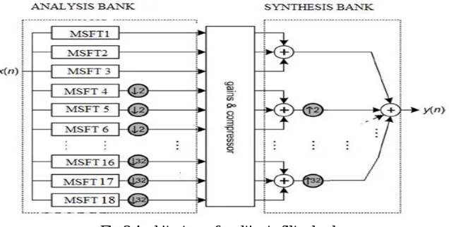
Multi rate filter bank is constructed from 18 independent MSFT filters. Fig. 3 illustrates the desired auditory compensation system based on this filter bank, in which the symbols x and y stand for the input and output sequences, respectively.
Fig.3 Architecture of multi rate filter bank
V. SIMULATION RESULTS
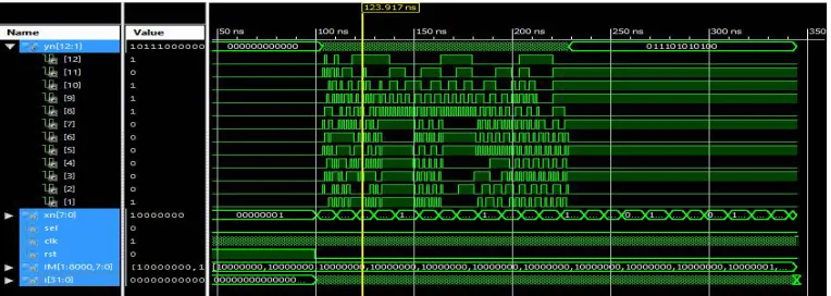
The modification to the second order frequency transformation filter and its application ie;the design of filter bank helps to overcome the limitation of existing techniques with improved performance. The Fig.4 shows the output response of MSFT filter.
Fig 4. Output response of MSFT Filter
The filter bank comprises of analysis bank, gain and compressor module and a synthesis bank. These three modules together produces the final output. The analysis bank divides the given input signals into different frequency ranges and provides necessary gain for the signals and these signals are given to the synthesis bank where the down sampling is performed and the final output is taken from the adder module. Fig 5 represents the output response of multi rate filter bank, with corresponding audio signals from MATLAB.
Fig 5. Output response of filter bank
VI.CONCLUSION AND FUTURE WORK
REFERENCES
1. SumedhDhabu, VinodAchutavarrier Prasad, “Design of Modified Second-Order Frequency Transformations Based Variable Digital Filters With Large Cut-off Frequency Range and Improved Transition Band Characteristics” IEEE Transactions On Very Large Scale Integration (VLSI) Systems 2015
2. SumedhDhabu,VinodAchutavarrier Prasad, “Design and FPGA implementation of variable Cut off Frequency filter based on continously variable fractional delay structure and interpolation technique” International Journal of Advances in Telecommunications, Electrotechnics, Signals and Systems Vol. 4, No. 3 (2015)
3. SumedhDhabu,VinodAchutavarrierPrasad, “Design of Modified Second-Order Frequency Transformations Based Variable Digital Filters With Large Cut-off Frequency Range and Improved Transition Band Characteristics” IEEE Transactions On Very Large Scale Integration (VLSI) Systems 2015 .
4. S. J. Darak, A. P. Vinod, and E. M.-K. Lai, “Design of variable linear phase FIR filters based on second order frequency transformations and coefficient decimation,” in Proc. IEEE Int. Symp. Circuits Syst., Seoul,South Korea, May 2012, pp. 3182–3185.
5. R. Mahesh and A. P. Vinod, “Low complexity flexible filter banks for uniform and non-uniform channelisation in software radios using coefficient decimation,” IET Circuits, Devices&Systems, vol. 5, no.3, pp. 232-242, May 2011.
6. R. Mahesh and A. P. Vinod, “Reconfigurable frequency response masking filters for software radio channelization,” IEEE Trans. Circuits Syst. II, Exp. Briefs, vol. 55, no. 3, pp. 274–278, Mar. 2008.
7. K. H. Chen and T. D. Chiueh, “A low power digit-based reconfigurable FIR filter,” IEEE Transactions on Circuits and Systems II, vol. 53, no. 8, pp. 617-621, Aug. 2006.
8. T. Solla and O. Vainio, “Comparison of programmable FIR filter architectures for low power,” Proceedings of 28th European Solid-State Circuits Conference, pp. 759-762, Italy, Sept. 2002.
9. H. R. Lee, C. W. Jen and C. M. Liu, “A new hardware efficient architecture for programmable FIR filters,” IEEE Transactions on Circuits and Systems II, vol. 43, no. 9, pp. 637-644, Sept. 1996.
10. Woo Jin Oh and Yong Hoon Lee, “Implementation of programmable multiplierless FIR filter with powers-of-two coefficients,” IEEE Transactions on Circuits and Systems II, vol. 42, no. 8, pp. 553-556, Aug. 1995.
11. A. G. Constantinides, “Spectral transformations for digital filters,” in Proceedings of the Institution of Electrical Engineers, vol. 117, no. 8, pp. 1585-1590, Aug. 1970.
12. A. G. Constantinides, “Spectral transformations for digital filters,” in Proceedings of the Institution of Electrical Engineers, vol. 117, no. 8, pp. 1585-1590, Aug. 1970.
BIOGRAPHY