University of Windsor University of Windsor
Scholarship at UWindsor
Scholarship at UWindsor
Electronic Theses and Dissertations Theses, Dissertations, and Major Papers
12-14-2015
Properties and applications of basalt fibre reinforced concrete
Properties and applications of basalt fibre reinforced concrete
John-Sebastian BranstonUniversity of Windsor
Follow this and additional works at: https://scholar.uwindsor.ca/etd
Recommended Citation Recommended Citation
Branston, John-Sebastian, "Properties and applications of basalt fibre reinforced concrete" (2015). Electronic Theses and Dissertations. 5628.
https://scholar.uwindsor.ca/etd/5628
This online database contains the full-text of PhD dissertations and Masters’ theses of University of Windsor students from 1954 forward. These documents are made available for personal study and research purposes only, in accordance with the Canadian Copyright Act and the Creative Commons license—CC BY-NC-ND (Attribution, Non-Commercial, No Derivative Works). Under this license, works must always be attributed to the copyright holder (original author), cannot be used for any commercial purposes, and may not be altered. Any other use would require the permission of the copyright holder. Students may inquire about withdrawing their dissertation and/or thesis from this database. For additional inquiries, please contact the repository administrator via email
PROPERTIES AND APPLICATIONS OF BASALT FIBRE
REINFORCED CONCRETE
By
John-Sebastian Branston
A Thesis
Submitted to the Faculty of Graduate Studies
through the Department of Civil and Environmental Engineering in Partial Fulfillment of the Requirements for
the Degree of Master of Applied Science at the University of Windsor
Windsor, Ontario, Canada
2015
PROPERTIES AND APPLICATIONS OF BASALT FIBRE
REINFORCED CONCRETE
By
John-Sebastian Branston
APPROVED BY:
__________________________________________________
S. Kenno, Special Member MEDA Limited, Windsor, Ontario
__________________________________________________
J. Sokolowski
Mechanical, Automotive & Materials Engineering
__________________________________________________
S. Cheng
Civil and Environmental Engineering
__________________________________________________
S. Das, Advisor
Civil and Environmental Engineering
iii
DECLARATION OF CO-AUTHORSHIP AND PREVIOUS
PUBLICATION
I. Co-Authorship Declaration
I hereby declare that this thesis incorporates material that is the result of joint research undertaken with Dr. Sara Kenno and Mr. Craig Taylor, of MEDA Limited, and my supervisor, Dr. Sreekanta Das, of the University of Windsor. In all cases, the key ideas, the primary contributions, and data analysis and interpretation were performed by the author of this thesis. The contributions of the co-authors were primarily focused on the provision of the study and suggesting possible directions. Results related to this research are reported in Chapters 2 and 3, inclusive.
I am aware of the University of Windsor's Senate Policy on Authorship and I certify that I have properly acknowledged the contributions of the other researchers to my thesis, and I have obtained written permission from my co-authors to include the above materials in my thesis.
I certify that, with the above qualification, this thesis, and the research to which it refers to, is the product of my own work.
II. Declaration of Previous Publication
This thesis includes 2 original papers that have been previously submitted for publication in peer reviewed journals, as follows:
Thesis Chapter Publication title/full citation Publication status
Chapter 2
Mechanical behaviour of basalt fibre reinforced concrete
Submitted, Construction and Building Materials
Chapter 3
Influence of basalt fibre on free and restrained plastic shrinkage
Submitted, Cement and Concrete Composites
I certify that I have obtained a written permission from the copyright owners to include the above published materials in my thesis. I certify that the above material describes work completed during my registration as graduate student at the University of Windsor.
iv
v
ABSTRACT
Basalt fibre has gained popularity in concrete reinforcing applications due to its
excellent mechanical properties and an environmentally friendly manufacturing process.
Research work presented in this thesis was undertaken to better understand potential
applications of three different types of basalt fibre construction: filament and bundle
dispersion fibres, and basalt fibre reinforced polymer bars (minibars). Mechanical
performance was evaluated by measuring the effect of the fibres on the pre- and
post-cracking behaviour of concrete, and by investigating how the fibre-concrete interfacial
properties influenced that behaviour. Durability was evaluated by measuring the effect of
the fibres on unrestrained plastic shrinkage, and their ability to prevent shrinkage
cracking when restraint is present. Results suggest that filament dispersion fibres can be
used for early-age crack control, minibars can replace rebar in applications for which it is
not vital, and further research is required on bundle dispersion fibres to enhance their
vi
ACKNOWLEDGEMENTS
I would first like to thank my advisor Dr. Sreekanta Das for inspiring an interest
in independent study by allowing me the freedom to pursue my own ideas, while also
providing enough input along the way to ensure those pursuits would amount to
something of practical benefit. I would also like to thank Mr. David Lawn, Dr. Sara
Kenno, and Mr. Craig Taylor from MEDA Limited for the financial support and technical
knowledge that made this project possible, in addition to their assistance with the
hands-on work in the lab and in the field.
Concrete work is very labour intensive and I would not have been able to
complete all of the work presented in this thesis without the skill and input of our lab
technicians Mr. Lucian Pop, Mr. Matt St. Louis, and Mr. Patrick Seguin. Additionally,
I’d like to express my gratitude for the advice and help I received from fellow students:
Jamshid Zohreh Heydariha, Hossein Ghaednia, Sahan Jayasuriya, Jason Duic, and Emad
Booya.
Finally, I am very appreciative of the support and encouragement I received from
my family and Kristen, particularly when things (often) did not go as smoothly as
vii
TABLE OF CONTENTS
DECLARATION OF CO-AUTHORSHIP AND PREVIOUS PUBLICATION ...III
ABSTRACT ... V
ACKNOWLEDGEMENTS ... VI
LIST OF TABLES ... X
LIST OF FIGURES ... XI
LIST OF APPENDICES ... XIV
CHAPTER 1 GENERAL INTRODUCTION ...1
1.1 INTRODUCTION TO FIBRE REINFORCED CONCRETE ...2
1.1.1 Basic Mechanics of Fibre Reinforced Concrete ...3
1.1.2 Steel Fibre Reinforced Concrete...5
1.1.3 Glass Fibre Reinforced Concrete ...5
1.1.4 Synthetic Fibre Reinforced Concrete ...6
1.1.5 Natural Fibre Reinforced Concrete ...8
1.2 INTRODUCTION TO BASALT FIBRE ...9
1.2.1 Manufacturing Process ...9
1.2.2 Beneficial Aspects of Basalt Fibre ...11
1.2.3 Problems to Overcome ...12
1.3 OBJECTIVE...13
1.4 METHODOLOGY ...13
1.5 ORGANIZATION OF THE THESIS ...14
1.6 REFERENCES ...14
CHAPTER 2 MECHANICAL BEHAVIOUR OF BASALT FIBRE REINFORCED CONCRETE ...17
2.1 INTRODUCTION ...17
2.2 EXPERIMENTAL PROCEDURE ...20
2.2.1 Materials ...20
2.2.2 Concrete Mix Design ...21
viii
2.3 RESULTS AND DISCUSSION ...24
2.3.1 Flexural Testing ...24
2.3.2 Impact Testing ...27
2.3.3 Interfacial Properties ...31
2.4 CONCLUSIONS ...35
2.5 ACKNOWLEDGEMENTS ...37
2.6 REFERENCES ...37
CHAPTER 3 INFLUENCE OF BASALT FIBRE ON FREE AND RESTRAINED PLASTIC SHRINKAGE ...40
3.1 INTRODUCTION ...40
3.2 EXPERIMENTAL PROCEDURE ...43
3.2.1 Environmental Chamber ...43
3.2.2 Free Shrinkage Testing ...44
3.2.3 Restrained Shrinkage Testing ...45
3.2.4 Materials and Specimen Preparation ...46
3.3 RESULTS AND DISCUSSION ...49
3.3.1 Mortar Flow ...49
3.3.2 Free Plastic Shrinkage ...50
3.3.3 Restrained Shrinkage ...54
3.4 CONCLUSIONS ...58
3.5 ACKNOWLEDGEMENTS ...59
3.6 REFERENCES ...60
CHAPTER 4 REHABILITATION OF DETERIORTATED CONCRETE BRIDGE STRUCTURE ...62
4.1 INTRODUCTION ...62
4.2 ORIGINAL CONDITION OF BRIDGE ...63
4.3 REPAIR METHODOLOGY...67
4.4 ASSESSMENT AFTER ONE YEAR ...69
4.5 DISCUSSION ...72
4.6 REFERENCES ...74
CHAPTER 5 GENERAL DISCUSSIONS AND CONCLUSIONS ...75
ix
5.2 BUNDLE DISPERSION FIBRES ...75
5.3 MINIBARS ...76
APPENDICES ...77
APPENDIX A COMPRESSIVE STRENGTH ...77
APPENDIX B FLEXURAL TESTING STATISTICAL ANALYSIS ...78
APPENDIX C IMPACT TESTING STATISTICAL ANALYSIS ...79
APPENDIX D EDS ANALYSIS OF SEM WORK ...85
APPENDIX E FIBRE PULL-OUT TESTING ...87
APPENDIX F LONG-TERM DRYING SHRINKAGE ...88
APPENDIX G PERMISSIONS ...90
x
LIST OF TABLES
Table 1.1: Properties of commonly used fibres ... 2
Table 1.2: Typical chemical composition of basalt and E-glass fibres... 10
Table 1.3: Comparison of basalt and E-glass fibres ... 11
Table 2.1: Test matrix ... 22
Table 2.2: Flexural testing results ... 26
Table 2.3: Impact testing results ... 28
Table 3.1: Mass proportions of concrete mixes used ... 47
Table 3.2: Fibre dosages and test matrix ... 48
Table 3.3: Flow of mortar ... 49
Table 4.1: Summary of repair techniques ... 69
Table A.1: Compressive strength of BF specimens ... 77
Table A.2: Compressive strength of MB and SF speimens ... 77
Table B.1: Statistical analysis of flexural testing specimens ... 78
Table C.1: Statistical analysis of N1 ... 83
Table C.2: Statistical analysis of N2 ... 84
xi
LIST OF FIGURES
Figure 1.1: Typical post-cracking behaviour of FRC ... 4
Figure 1.2: Classification of natural fibres ... 8
Figure 1.3: Basalt fibre products developed for concrete reinforcing ... 10
Figure 2.1: Fibres used in experimental work ... 21
Figure 2.2: Flexural test setup ... 22
Figure 2.3: Impact test fixture ... 23
Figure 2.4: Close-up of impact piston and typical first-crack ... 24
Figure 2.5: Typical flexural test results for BF specimens ... 25
Figure 2.6: Typical flexural test results for MB specimens ... 25
Figure 2.7: Cracked cross-section of failed flexural test specimens ... 27
Figure 2.8: Impact test results of BF specimens ... 29
Figure 2.9: Impact test results of MB and SF specimens ... 29
Figure 2.10: Cracked cross-section of failed impact test specimens ... 30
Figure 2.11: SEM images of fibres in concrete after 7 days ... 32
Figure 2.12: Cracked cross-section of BF-50-12 impact specimen after 9 months ... 33
Figure 2.13: Change in cement density on fibre surface over time ... 34
Figure 2.14: Change in fibre surface after immersion in concrete ... 34
Figure 3.1: Environmental chamber ... 44
Figure 3.2: Free plastic shrinkage test setup ... 45
Figure 3.3: Restrained shrinkage testing ... 46
Figure 3.4: Difference in dispersion of fibres used in this study ... 48
Figure 3.5: Mean curves for development of strain over time ... 50
Figure 3.6: Mean strain values measured after four hours in control mix ... 51
xii
Figure 3.8: Mean strain values measured after four hours ... 53
Figure 3.9:Crack reduction with increasing fibre dosage ... 55
Figure 3.10: Effect of fibres on total crack area on specimen surface ... 55
Figure 3.11: Effect of fibres on crack width on specimen surface ... 56
Figure 3.12: Crack development without and with fibre ... 56
Figure 3.13: Effect of FD-25 on crack area in low w/c ratio mix ... 57
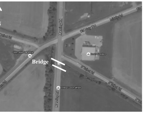
Figure 4.1: Location of bridge ... 64
Figure 4.2: East-end wing wall repairs ... 64
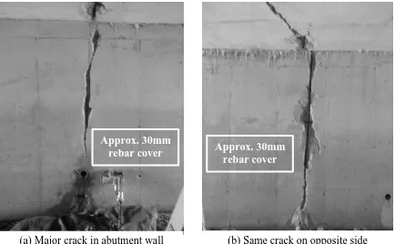
Figure 4.3: Major continuous crack at mid-span of abutment walls... 65
Figure 4.4: Major continuous crack at mid-span of deck soffit ... 65
Figure 4.5: West-end deck soffit ... 66
Figure 4.6: East-end of bridge deck ... 66
Figure 4.7: Patching repair methodology... 67
Figure 4.8: Cast-in-place concrete repair ... 68
Figure 4.9: East-end wing wall repairs after one year ... 70
Figure 4.10: Major continuous crack at mid-span of abutment walls after on year ... 70
Figure 4.11: Major continuous crack at mid-span of deck soffit after one year ... 71
Figure 4.12: West-end deck soffit after one year ... 71
Figure 4.13: East-end deck after one year ... 71
Figure 4.14: Rust deposit on surface of east-end wing wall ... 73
Figure C.1: Q-Q plot of PC specimens ... 79
Figure C.2: Histogram with normal distribution curve overlayed (N1 of PC) ... 79
Figure C.3: Histogram with normal distribution curve overlayed (N2 of PC) ... 80
Figure C.4: Q-Q plot of BF-50-8 specimens ... 80
Figure C.5: Histogram with normal distribution curve overlayed (N1 of BF-50-8) ... 81
xiii
Figure C.7: Q-Q plot of MB-43-20 specimens ... 82
Figure C.8: Histogram with normal distribution curve overlayed (N1 of MB-43-20) ... 82
Figure C.9: Histogram with normal distribution curve overlayed (N2 of MB-43-20) ... 83
Figure D.1: SEM images of fibre surface ... 85
Figure D.2: EDS spot analysis of fibre as received ... 85
Figure D.3: EDS spot analysis of fibre after 7 days in cement ... 85
Figure E.1: Pull-out test setup ... 87
Figure E.2: Test specimen... 87
Figure E.3: Load-deflection plot after one day ... 87
Figure E.4: Load-deflection plot after 28 days ... 87
Figure F.1: Concrete prisms ... 88
Figure F.2: Scale and length comparator ... 88
Figure F.3: 120 day shrinkage of BD-25 specimens... 88
Figure F.4: 28 day shrinkage of FD-25 specimens ... 89
xiv
LIST OF APPENDICES
Appendix A Compressive Strength ... 77
Appendix B Flexural Testing Statistical Analysis ... 78
Appendix C Impact Testing Statistical Analysis ... 79
Appendix D EDS Analysis of SEM Work ... 85
Appendix E Fibre Pull-out Testing ... 87
Appendix F Long-term Drying Shrinkage ... 88
1
CHAPTER 1
GENERAL INTRODUCTION
Concrete is arguably the most widely used construction material in the world.
Therefore, it comes as no surprise that a vast amount of research has been undertaken to
enhance its performance; making it possible to build larger, safer, and more economical
structures that are durable in a wider range of environments. One area of research that has
been growing in the last few decades is the use of discrete, randomly distributed fibres to
produce a composite material called fibre reinforced concrete (FRC). However, the idea
of reinforcing brittle materials with fibres dates back to ancient times, where straw was
used to reinforce mud bricks [1]. Even then the benefits of the composite system were
apparent, in which the fibres are effective in restricting the development of cracks, and as
a result, preventing sudden, potentially catastrophic, brittle failures due to the low tensile
strength and strain capacity of plain concrete (PC).
More recently, asbestos fibre cement products were used successfully at a
commercial scale during the early 1900s. Health concerns about asbestos during the
1950s sparked the introduction of steel fibre reinforced concrete (SFRC). Although well
received, steel fibre reinforcement suffered from a few problems, namely difficulty with
mixing, handling and placing fresh concrete with high fibre dosages, and susceptibility to
corrosion. Consequently, a substantial amount of further experimental work has since
been undertaken into alternative materials, which will be the topic of further discussion in
2
1.1 INTRODUCTION TO FIBRE REINFORCED CONCRETE
In general, areas of improvement in FRC over PC include: tensile strength,
compressive strength, elastic modulus, crack resistance, crack control, durability, fatigue
life, resistance to impact and abrasion, shrinkage, expansion, thermal characteristics and
fire resistance [1].Some commonly used types of fibres are shown below in Table 1.1.
Table 1.1 Properties of commonly used fibres [2]
Fibre Type Diameter
(µm) Specific Gravity Elastic Modulus (GPa) Tensile Strength (GPa) Elongation at Break (%)
Steel 5-500 7.84 200 0.5-2 0.5-3.5
Glass 9-15 2.6 70-80 2-4 2-3.5
Asbestos 0.02-0.4 2.6-3.4 164-196 3.1-3.5 2-3
Polypropylene 20-400 0.9-0.95 3.5-10 0.45-0.76 15-25
Aramid (Kevlar) 10-12 1.44 63-120 2.3-3.5 2-4.5
Carbon 8-9 1.6-1.7 230-380 2.5-4 0.5-1.5
Nylon 23-400 1.14 4.1-5.2 0.75-1 16-20
Cellulose - 1.2 10 0.3-0.5 -
Acrylic 18 1.18 14-19.5 0.4-1 3
Polyethylene 25-1000 0.92-0.96 5 0.08-0.6 3-100
Wood Fibre - 1.5 71 0.9 -
Sisal 10-50 1.5 - 0.8 3
Cement Matrix - 1.5-2.5 10-45 0.003-0.007 0.02
The physical and mechanical properties of the fibres are not the only aspects that
should be considered when evaluating their potential use in FRC. Factors such as the
chemical durability of the fibres in the alkaline environment of concrete, and the
increased difficulty of working with the fresh FRC also require careful consideration
when selecting the most suitable type of fibre for a specific application. However, these
factors are not as straightforward to quantify as those presented in Table 1.1. For
3
change when using different concrete mixes or production methods. Moreover, due to the
uncertainty of accelerated testing, it can take many years of in-situ observation to
evaluate the durability of the fibres, or that of the FRC composite as a whole. Therefore,
it can be difficult to assess if the benefits of adding fibres are justified in the long-term.
The following sub-sections will discuss the basic mechanics of FRC and some typical
applications of some commonly used fibres, before delving into more detail on basalt
fibre.
1.1.1 Basic Mechanics of Fibre Reinforced Concrete
The major draw of using FRC is the enhancement of post-cracking behaviour by
restricting crack growth. As a result, the addition of fibres has two primary beneficial
effects [2]:
1. Increase in the strength of the composite by transferring stress across the cracks.
This behaviour is characterized by an ascending stress-strain curve following the
first-crack, or strain hardening.
2. Increase in the toughness of the composite by providing an energy absorption
mechanism. The mechanism is the result of the gradual pull-out of the fibres,
which is reflected in the descending part of a stress-strain curve, or strain
softening.
The behaviour of the composite following the first-crack depends on the load bearing
capacity of the fibres. After cracking, a number of outcomes are possible depending on
the material used. For example, using fibres with an elastic modulus and tensile strength
greater than the concrete (matrix) would result in an increase in the pre-cracking strength,
4
However, if the fibre elastic modulus was lower than that of the matrix, the fibre would
deform with the matrix, and offer no increase to first-crack strength. On the other hand, a
fibre that has a poor bond with the matrix would pull-out shortly after cracking occurs,
and thus, not offer much increase in toughness. These types of variations in behaviour are
illustrated in Fig. 1.1.
Apart from the use of different materials, the behaviour of FRC composites can be
altered by a number of methods. The post-cracking behaviour can be enhanced by
modifying the fibre-matrix contact area. This can be achieved by changing the fibre
length or diameter (aspect ratio), or by introducing mechanical anchorage through
different geometries (e.g. fibrillated or hooked end fibres). The load bearing capacity of
the composite can be enhanced by increasing fibre quantity (without adversely effecting
consolidation), or by favourable orientation of the fibres (e.g. spray-up process versus
random orientation from traditional mixing). Finally, behaviour can also be altered by
changes to the matrix, such as the use of different cements, aggregates, material
proportions, and production methods.
5
Independent of these methods, the behaviour of the composite can also be
expected to change over time. The material properties of concrete change due to on-going
curing and environmental interaction, and the load bearing capacity of the fibres can
change depending on their chemical stability in the alkaline environment of concrete.
1.1.2 Steel Fibre Reinforced Concrete
The most significant benefits of steel fibre reinforced concrete (SFRC) are an
increase in toughness and reduction in cracking severity. Increases in first-crack strength
with SFRC are relatively small [2]. Thus, the most typical application of SFRC is to
replace traditional steel rebar when it is not essential for the safety and integrity of the
structure, such as slabs-on-grade, pavements, and tunnel linings [1]. Steel fibres are also
useful in flexural members as a secondary reinforcement, in which they can enhance
resistance to dynamic loads (impact, fatigue, blast, and seismic loading) and changes in
temperature and humidity [2].
Although steel fibres can decrease construction costs by reducing the required
thickness of structures and eliminating the labour required to install mesh and rebar, the
cost of steel fibres at a modest dosage of 1% (by volume) can double the material cost of
the concrete [3]. For this reason, the use of SFRC has been limited to speciality
applications, such as large industrial floors and airport pavements. Moreover, steel fibres
are susceptible to corrosion due to the ingress of water and chlorides, and they increase
the dead-load of the structure.
1.1.3 Glass Fibre Reinforced Concrete
Glass fibres are lighter and stronger than steel fibres (see Table 1). Hence, glass
6
architectural elements. Most notable is façade panels, which make up 80% of GFRC
production [4]. Glass fibres can also be mixed into concrete at higher dosages than steel
fibres. As a result, the first-crack strength of GFRC is considerably higher than that of the
unreinforced matrix [2].
However, applications of GFRC have largely been limited to architectural
applications due to the poor chemical stability of the fibres in concrete. It has been well
established that regular E-glass fibres will lose their tensile strength due to high
alkalinity. To overcome this problem, alkali-resistant glass fibres (AR-glass) were
developed by adding zirconia to the fibres during manufacturing. Additionally, the use of
high-alumina cements and the addition of pozzolans (e.g. metakaolin) has been shown to
increase the durability of GFRC [5, 6]. Despite these advances, the long-term
performance of GFRC remains a primary concern.
1.1.4 Synthetic Fibre Reinforced Concrete
A variety of synthetic fibres, with a broad spectrum of mechanical properties,
have been developed for concrete reinforcing applications. The fibres are generally
categorized by their modulus of elasticity with respect to that of the matrix: if it is higher
they are called high modulus fibres, and if it is lower they are called low modulus fibres.
The key difference being that high modulus fibres can increase the first-crack strength of
the composite, whereas low modulus fibres can not [2].
1.1.4.1 High Modulus Synthetic Fibre
The majority of research in this area has focused on aramid (Kevlar) and carbon
fibres. FRC made with these fibres exhibits comparable mechanical behaviour to steel
7
and good durability [7, 8]. However, widespread application has been prohibited due to
their high cost. One method to get cost-effective benefit from the fibres is by using a
hybrid reinforcing system. Li et al. [9] found that a combination of steel and carbon fibres
was very effective in increasing both strength and toughness. In that case, the smaller,
well distributed carbon micro-fibres increased the first-crack strength by preventing the
propagation of micro-cracks, and the steel fibres increased the toughness due to their high
ultimate strain capacity. Current application of these fibres is limited to speciality
structures where light-weight and stiffness is desirable, such as single and double
curvature membrane structures and scaffold boards [1].
1.1.4.2 Low Modulus Synthetic Fibre
Commonly used low modulus synthetic fibres include: polypropylene,
polyethylene, and nylon. The main draw of the fibres is their good alkaline resistance and
low cost. However, they suffer from a lack of fire resistance, and a poor bond with the
cement matrix [2]. For these reasons, the most typical use of low modulus synthetic fibres
has been for crack control. Low dosages of polypropylene fibres (< 0.3% by volume)
have been shown to eliminate cracking due to plastic shrinkage [10]. However, Song et
al. [11] found that nylon fibres outperform polypropylene fibres in the reduction
shrinkage cracking and attributed it to their higher tensile strength. The use of nylon
fibres may be limited to low dosages for crack control, since they are hydrophilic and
absorb mix water, which can be problematic at the higher dosages necessary to enhance
mechanical behaviour [2]. In regards to mechanical properties, polyethylene fibres were
shown to outperform polypropylene fibres in terms of flexural strength and impact
8
in regards to enhancing the properties of these fibres is done in the private sector and not
available in open literature. However, one obvious method that has been adopted is the
use of fibrillations in the fibre to enhance the mechanical bond with the matrix.
1.1.5 Natural Fibre Reinforced Concrete
In general, research into the use of natural fibres has been undertaken to develop
an economical and environmentally friendly alternative to manufactured fibres and
traditional rebar. A lot of research is inspired by the idea of taking advantage of
abundant, low-cost, locally available materials to enhance construction in the developing
world. There are many types of natural fibres, and thus, discussion in this sub-section
only provides a broad overview. Biagiotti et al. [13] categorized some commonly used
natural fibres, as can be seen below in Fig. 1.2.
Natural fibre reinforced concrete follows the same type of behaviour as discussed
in the previous sub-sections. Mechanical properties, such as the modulus of rupture, and
toughness, are further enhanced with higher fibre dosages [1]. However, workability and
proper consolidation puts an upper limit on the dosage. Fibres with a comparatively high
9
tensile strength and elastic modulus, such as flax, jute, and hemp, are typically best for
increasing flexural strength and elastic modulus. On the other hand, coarser fibres, such
as sisal and coir, are better in terms of increasing toughness [13]. In regards to durability,
flax, sisal, coconut, and cellulose fibres have been shown to prevent early age cracking
due to shrinkage [14-16]. In general, the greatest drawbacks of natural fibres are their
lack of durability in concrete due to alkalinity and biological attacks, and inconsistency in
mechanical properties [2].
1.2 INTRODUCTION TO BASALT FIBRE
1.2.1 Manufacturing Process
Basalt is an igneous rock found in abundance throughout the world. Basalt rock is
crushed, loaded into a furnace and liquefied. Next, basalt filaments are drawn through
platinum-rhodium bushings. As the filaments cool, they are coated with a sizing agent.
The sizing agent is necessary to prevent abrasion during transportation; however, it also
provides manufacturers with a way to differentiate their fibre from their competitor’s. For
example, the performance of E-glass fibre depends on parameters such as fibre volume
and aspect ratio, but the fibre itself differs little from manufacturer to manufacturer. In
regards to interfacial properties (e.g. bond strength and alkaline resistance), sizing is the
primary variable [17]. Basalt fibres used in this study were manufactured with two
different sizings. The first type of sizing keeps bundles of filaments together during
transportation and handling, but allows them to disperse uniformly when mixed into the
concrete. The second type of sizing has stronger adhesive properties and keeps the
bundles of filaments together during mixing. These two types of fibre are called filament
10
reinforce polymers to produce fibre reinforced polymer (FRP) rebar. A similar technique
has recently been applied on a smaller scale to produce basalt minibars [18]. The
minibars are an epoxy based resin reinforced with basalt filaments. They are more rigid
than plain chopped fibres and have similar dimensions to standard steel fibres. Fig. 1.3
shows some common basalt fibre products developed for reinforcing concrete.
In general, the manufacturing process and chemical composition of basalt fibre is
similar to that of glass fibre [19]. A comparison of the chemical composition of the fibres
is shown in Table 1.2.
Table 1.2. Typical chemical composition of basalt and e-glass fibres [19]
Fibre Type
Weight % of compound
SiO2 Al2O3 CaO MgO B2O3 Na2O K2O Fe2O3
Basalt 52-58 17-18 5-8 1-4 - 3-6 1-5 4-10
E-glass 52-56 12-16 16-25 0-5 5-10 0.8 0.2-0.8 >0.3
Glass fibre is currently used to a much greater extent in concrete reinforcing applications.
Therefore, further discussion will use glass fibre as a basis of comparison for basalt fibre.
Fig. 1.3 Basalt fibre products developed for concrete reinforcing
11
1.2.2 Beneficial Aspects of Basalt Fibre
Basalt fibres can be manufactured directly from a single raw material (basalt rock)
without the need for additives, making the process simpler than that of glass fibre [20].
As a result, the fibres can be manufactured with conventional processes and equipment,
and less energy, which offers an economic advantage [21]. Moreover, the fibres are
considered 100% natural, have no toxic reaction with air or water, and the fiberization
process is said to be more environmentally friendly than that of glass fibre [19]. In terms
of mechanical and physical properties, basalt fibre has gathered attention due to its high
elastic modulus, high strength, corrosion resistance, high temperature resistance, and
light-weight [19]. Table 1.3 compares some physical and mechanical properties of basalt
and E-glass fibres.
Table 1.3 Comparison of basalt and E-glass fibres [21]
Fibre Type
Density (g/cm3)
Elastic Modulus (GPa) Tensile Strength (GPa) Elongation at Break (%)
Basalt 2.8 89 2.8 3.15
E-glass 2.56 76 1.4-2.5 1.8-3.2
In general, research into using basalt fibre as a concrete reinforcing material has
grown in popularity because of its potential to replace glass fibre. Basalt fibre is often
reported to offer better mechanical properties and a more economical, environmentally
friendly manufacturing process. With such good characteristics, and its manufacturing
process dating back to 1923 [19], it seems to be quite a mystery as to why its use has
been so limited in the FRC industry; the following sub-section will discuss some possible
12
1.2.3 Problems to Overcome
A key concern with basalt fibre is its chemical durability. Its alkaline resistance is
often said to be good, on the basis that it may be better than that of E-glass. For example,
one basalt fibre manufacturer states the fibre is very durable based on a weight loss of
only 0.35% after immersion in a cement solution, in comparison to E-glass fibre that lost
4.5% of weight [22]. However, this is very indirect justification, since focus should be on
the stability of the mechanical properties and matrix-fibre bond strength over time, when
considering their application in concrete reinforcing. Lee et al. and Rabinovich et al. [23,
24] have shown basalt fibre loses tensile strength over time in a calcium hydroxide
solution intended to replicate hydrating cement. In these cases, basalt fibre generally
retained more strength than E-glass fibre. However, the improvement may be considered
trivial when after 90 days, the basalt fibres still lost more than 50% of its tensile strength.
There is a lack of research into the fibre-matrix bond strength, and how it changes with
time. This will be discussed further in Chapter 2.
The issue of chemical durability may be further complicated by differences in
basalt fibre produced by different manufacturers. Although production from a single raw
material can be considered beneficial, it also means that manufacturers have less control
over the consistency of the final product. The chemical composition and crystalline
structure of basalt rock varies greatly by geographical location. Therefore, only select
basalt rock can produce filaments with desirable properties [17]. As a result, the market
share of basalt fibre has been reduced due to variability in the material properties of
fibres manufactured with raw material from different locations [25]. Furthermore,
13
market. Thus, it may be difficult to quantify interfacial properties, since they may differ
significantly when using fibres purchased from different manufacturers.
1.3 OBJECTIVE
The objective of this research is to evaluate the relative merit of basalt bundle
dispersion fibres, filament dispersion fibres, and minibars in enhancing the mechanical
behaviour and durability of concrete. Based on the results, suggestions for the most
suitable application of each type of fibre are made.
1.4 METHODOLOGY
The experimental work in this thesis was completed in three distinct phases. Lab
work was undertaken to quantify the effect of fibre type, length and dosage on the
mechanical behaviour of concrete, and then on the durability. Additionally, an old
deteriorated concrete bridge structure was repaired using basalt fibre reinforced concrete.
The mechanical behaviour of basalt fibre reinforced concrete was evaluated
through four fundamental properties: compressive strength, split-tensile strength, flexural
strength and, impact resistance. The influence of the fibres on the first-crack strength and
the post-cracking behaviour was measured and then compared with that of unreinforced
control specimens, as well as specimens reinforced with industry standard hooked-end
steel fibres. Moreover, fibre-matrix pull-out testing was completed, and scanning electron
microscopy was used, in order to better understand how the fibre-matrix interfacial
properties influenced the mechanical behaviour of the composite.
The durability of basalt fibre reinforced concrete was evaluated by shrinkage
14
phase, concrete specimens were unrestrained in order to study the influence of the fibre
on the free plastic shrinkage strain. In the second phase, a high-strength concrete
sub-base was used to restrain the shrinkage movement in order to study the effect of the fibres
on reducing plastic shrinkage cracking. The influence of the fibres on the unrestrained,
long-term (drying) shrinkage was also studied for 120 days.
The practicality of basalt fibre reinforced concrete was evaluated by repairing a
concrete bridge structure (box culvert) constructed sometime between the 1950s and
1960s. Sprayed-on patching repairs on the abutment walls and soffit were made with a
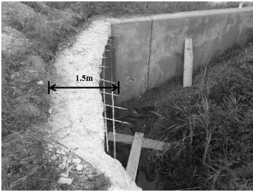
cement-based mortar material reinforced with basalt fibre. Approximately 1 m3 of deteriorated concrete at the end of the bridge deck was replaced with cast-in-place basalt
fibre reinforced concrete. Measurements were made after one year by visual comparison
between areas reinforced with basalt fibre versus those that were not.
1.5 ORGANIZATION OF THE THESIS
This thesis is written in paper format and it consists of five chapters. The first
chapter provides a general introduction into fibre reinforced concrete and introduces the
potential role of basalt fibre.
The second chapter investigates the pre- and post-cracking behaviour of basalt
fibre reinforced concrete under flexural and impact loading, and how the interfacial
properties influence that behaviour.
The third chapter investigates the influence of the fibres on the development of
shrinkage strain (unrestrained shrinkage), and their ability to restrict the development of
15
The fourth chapter highlights repair work completed on an old bridge structure,
and examines the durability of those repairs after one year.
The fifth chapter provides a summary of how the previous chapters are related,
general conclusions, and recommendations for future application and research work.
1.6 REFERENCES
[1] ACI Committee 544. 544.1R-96: Report on fiber reinforced concrete (Reapproved 2009). Technical Documents. 1996.
[2] Bentur A, Mindess S. Fibre reinforced cementitious composites: CRC Press; 2006.
[3] Van Chanh N. Steel fiber reinforced concrete. Faculty of Civil Engineering Ho chi minh City University of Technology Seminar Material. 2004. p. 108-16.
[4] Ferreira J, Branco F. The use of glass fiber–reinforced concrete as a structural material. Experimental Techniques. 2007;31(3):64-73.
[5] Majumdar A, Singh B, Ali M. Properties of high-alumina cement reinforced with alkali resistant glass fibres. Journal of Materials Science. 1981;16(9):2597-607.
[6] Marikunte S, Aldea C, Shah SP. Durability of glass fiber reinforced cement
composites:: Effect of silica fume and metakaolin. Advanced Cement Based Materials. 1997;5(3):100-8.
[7] Briggs A. Carbon fibre-reinforced cement. Journal of Materials Science. 1977;12(2):384-404.
[8] Nanni A. Properties of aramid-fiber reinforced concrete and SIFCON. Journal of Materials in Civil Engineering. 1992;4(1):1-15.
[9] Yao W, Li J, Wu K. Mechanical properties of hybrid fiber-reinforced concrete at low fiber volume fraction. Cement and Concrete Research. 2003;33(1):27-30.
[10] Banthia N, Gupta R. Influence of polypropylene fiber geometry on plastic shrinkage cracking in concrete. Cement and Concrete Research. 2006;36(7):1263-7.
[11] Song P, Hwang S, Sheu B. Strength properties of nylon-and polypropylene-fiber-reinforced concretes. Cement and Concrete Research. 2005;35(8):1546-50.
[12] Soroushian P, Khan A, Hsu J-W. Mechanical properties of concrete materials
16
[13] Biagiotti J, Puglia D, Kenny JM. A review on natural fibre-based composites-part I: structure, processing and properties of vegetable fibres. Journal of Natural Fibers.
2004;1(2):37-68.
[14] Boghossian E, Wegner LD. Use of flax fibres to reduce plastic shrinkage cracking in concrete. Cement and Concrete Composites. 2008;30(10):929-37.
[15] Soroushian P, Ravanbakhsh S. Control of plastic shrinkage cracking with specialty cellulose fibers. ACI Materials Journal. 1998;95(4).
[16] Toledo Filho RD, Ghavami K, Sanjuán MA, England GL. Free, restrained and drying shrinkage of cement mortar composites reinforced with vegetable fibres. Cement and Concrete Composites. 2005;27(5):537-46.
[17] CompositesWorld. Basalt Fiber: Alternative to Glass? 2006.
www.compositesworld.com/articles/basalt-fibers-alternative-to-glass (accessed September 17, 2015).
[18] ReforceTech. reforetech.com. (accessed November 3, 2015)
[19] Jamshaid H, Mishra R. A green material from rock: basalt fiber–a review. The Journal of The Textile Institute. 2015:1-15.
[20] Singha K. A short review on basalt fiber. International Journal of Textile Science. 2012;1(4):19-28.
[21] Fiore V, Scalici T, Di Bella G, Valenza A. A review on basalt fibre and its composites. Composites Part B: Engineering. 2015;74:74-94.
[22] Kamenny Vek. http://www.basfiber.com/2. (accessed October 1, 2015).
[23] Lee JJ, Song J, Kim H. Chemical stability of basalt fiber in alkaline solution. Fibers and Polymers. 2014;15(11):2329-34.
[24] Rabinovich F, Zueva V, Makeeva L. Stability of basalt fibers in a medium of hydrating cement. Glass and Ceramics. 2001;58(11-12):431-4.
17
CHAPTER 2
MECHANICAL BEHAVIOUR OF BASALT FIBRE
REINFORCED CONCRETE
2.1 INTRODUCTION
Plain concrete (PC) is a brittle material with low tensile strength. Consequently,
PC is susceptible to cracking due to tensile stress. When mixed into concrete, randomly
distributed fibres are able to bridge these cracks and arrest their development. By this
mechanism, it has been well established that the addition of fibres can enhance the
mechanical behaviour of PC. Although a variety of fibre reinforcing materials exist, fibre
reinforced concrete (FRC) used for structural applications is most often made with steel
fibres. The most beneficial properties of steel fibre reinforced concrete (SFRC) are
improved flexural toughness, flexural fatigue endurance, and impact resistance [1]. As a
result, steel fibres are able to totally or partially replace traditional steel rebar in many
applications, such as industrial floors and pavements. However, SFRC poses several
issues, such as: increased dead-load, reduced workability, fibre balling at high dosages,
and susceptibility to corrosion. For these reasons, glass fibre is a popular alternative.
Glass fibre reinforced concrete (GFRC) has been used extensively to produce thin,
light-weight architectural elements, most notably exterior facade panels. However, GFRC has
been largely limited to architectural applications due to durability concerns with the
fibres in the alkaline environment of concrete. It should be noted FRC made with a
variety of natural and synthetic fibres, including carbon, aramid, polypropylene, and
18
of concrete [1]. However, these fibres are not currently used as commonly as steel and
glass fibres in practical applications.
Basalt fibre has recently gained popularity as a potential competitor in concrete
reinforcing applications due to its excellent mechanical properties and an
environmentally friendly manufacturing process [2]. The fibres typically have a tensile
strength slightly higher than E-glass fibres and many times greater than steel fibres. In
addition to plain, chopped basalt fibres (BF), a new basalt concrete reinforcement product
called minibars (MB) has recently been developed. The minibars are essentially a scaled
down version of basalt fibre reinforced polymer rebar.
The research into basalt fibre reinforced concrete (BFRC) has largely been
focused on fundamental mechanical properties: compressive, split-tensile, and flexural
strength. In the case of BF, the research shows general agreement with the addition of
fibres being beneficial up to approximately 0.3-0.5% by volume and detrimental
thereafter [3-5]. However, optimum fibre dosages vary significantly in different types of
concrete, such as geopolymer [6] and high-strength concretes [7]. By comparison, MB
have been shown to be beneficial at dosages up to 4% by volume [8]. The influence of
BF and MB on compressive strength is typically not significant [3, 5-10], although it has
been shown to increase by as much as 31% with filament dispersion BF [4]. The primary
benefit of BF and MB in concrete under compression is the shift from a brittle failure
mode to a more ductile one [5, 7, 8, 10].
It has been shown that both BF and MB can significantly increase the tensile
strength of concrete [3-9]. However, it is difficult to assess the magnitude of the increase
split-19
tensile, and flexural tests. An increase of 43% in direct tensile strength was found using
BF with added zirconia, in comparison to a 14% increase without zirconia [9]. Zirconia is
added to E-glass fibre to produce alkaline resistant glass fibre. This may suggest that the
BF is susceptible to a similar mechanism of degradation as glass fibre in concrete.
Moreover, Jiang et al. [5] found the beneficial effects of BF diminished significantly after
90 days.
Research related to characterizing the post-cracking performance of BFRC has
been limited. This is a problem because in many practical applications, first-crack
strength is not increased. Rather, the most significant enhancement from the addition of
fibres is the post-cracking response [1]. Both BF and MB have been shown to enhance
the flexural toughness of concrete [5, 6, 8, 10]. However, it is difficult to assess the
relative merit of each product since results are based on different test methods. It was
found using the ACI Committee 544 recommended drop-weight test for impact resistance
[11] that BF can significantly enhance performance after cracking [10]. However, the
conclusion is based on data from four or six specimens per concrete mix. The test method
is notorious for large variations, requiring approximately 40 specimens per mix to keep
the percent error of measured mean values below 10% [12, 13]. Li and Xu [14] found BF
can significantly increase the energy absorption capacity of geopolymer concrete under
impact loading by using a Split-Hopkinson pressure bar system. However, the
performance of BFRC under impact in general is still largely unknown. Since impact test
results obtained by different test methods are generally not comparable [15], the results
from a simple test method may provide a more practical reference for which future
20
new composite and further development is expected to enhance its material properties for
concrete applications.
The purpose of the experimental work presented in this paper is to compare the
pre- and post-cracking mechanical behaviour of concrete reinforced with plain chopped
basalt fibres (BF), basalt minibars (MB), and commonly used hooked end steel fibres
(SF). Comparative performance is evaluated by flexural and drop-weight impact testing.
Interfacial properties are also investigated by scanning electron microscopy. It should be
noted that two types of plain chopped BF are available: filament dispersion and bundle
dispersion. Bundle dispersion fibres are manufactured with a sizing that holds bundles of
basalt filaments together during mixing, whereas filament dispersion fibres will disperse
into individual filaments. In this study, bundle dispersion fibres were selected since
filament fibres are typically used for crack control. Compressive strength was measured
as a means of quality control (see Appendix A). However, the data is not discussed
further since it has been well established that the influence of fibres on compressive
strength is generally insignificant.
2.2 EXPERIMENTAL PROCEDURE
2.2.1 Materials
All concrete was made with type 10 general use Portland cement conforming to
the Canadian standard CSA A3001 [16], regular drinking water, and well-graded
aggregates purchased locally. Superplasticizer was used in higher dosage FRC mixes.
Two different lengths of chopped BF were used: 36 mm and 50 mm. The BF
bundles are flat, approximately 0.6 mm wide and made of 16 μm diameter filaments. The
21
filaments. The composite is 43 mm in length and approximately 0.65 mm in diameter. By
comparison with the BF, the MB are more rigid. The SF used in this study are 38 mm in
length, 0.9 mm in diameter and have hooked ends. The fibres used in this study are
shown in Fig. 2.1.
2.2.2 Concrete Mix Design
Concrete specimens used in this study were cast with a 0.5 w/c ratio and
proportions of 1:1.4:2.8 by mass of cement, fine aggregate, and coarse aggregate. Three
different dosages were used for each type of basalt reinforcement, ranging from a low
dosage to the maximum mixable dosage. Despite the use of superplasticizer, it was found
that dosages beyond 12 kg/m3 and 40 kg/m3 for BF and MB, respectively, led to fibre balling and difficulty achieving proper consolidation. A summary of the mix types used
in this work is shown in Table 2.1. Mix designation is labelled according to fibre type,
fibre length, and dosage. For example, mix designation BF-36-8 indicates chopped basalt
bundle dispersion fibres of 36 mm length were used at a dosage of 8 kg per 1 m3 of plain concrete (8 kg/m3).
Fig. 2.1. Fibres used in experimental work
22
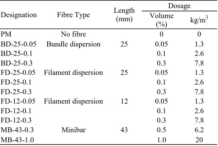
Table 2.1. Test Matrix
Mix
Designation Fibre Type
Length (mm)
Dosage
kg/m3 Volume (%)
PC No fibre 0 0
BF 36-4 Bundle dispersion 36mm 4 0.15
BF 36-8 8 0.31
BF 36-12 12 0.46
BF 50-4 50mm 4 0.15
BF 50-8 8 0.31
BF 50-12 12 0.46
MB 43-6 Minibar 43mm 6.2 0.31
MB 43-20 20 1
MB 43-40 40 2
SF 38-40 Steel 38mm 40 0.51
2.2.3 Test Methods
Flexural testing was completed following the guidelines of ASTM C1609 [17].
Concrete prisms 610 mm in length and 152 mm by 152 mm in cross-section were
subjected to third-point loading using a compression testing machine with a 2,200 kN
capacity. Mid-span deflection was measured using a 25 mm linear displacement
transducer (LDT). Mean values reported for each mix designation are based on three
specimens tested after 28 days of curing. The test setup is shown in Fig. 2.2.
23
Impact resistance was evaluated using a modified version of the ACI Committee
544 recommended drop-weight impact test [11], as recommended by Badr and Ashour
[12]. Concrete was cast in standard 152 mm diameter by 305 mm cylindrical moulds with
25.4 mm triangular pieces of wood attached to each side to form notches. Test specimens
51 mm in thickness were cut from the notched cylinders using a diamond blade saw. The
number of blows from a 4.54 kg compaction hammer with a 457 mm (18 in.) drop
required to cause a visible surface crack and subsequent failure were recorded for each
specimen. Failure was defined by either complete separation of the specimen, separation
such that the specimen is touching both sides of the fixture, or the impact piston was fully
embedded in the concrete. Moreover, only specimens that cracked through a line between
the notches were included in the data. Mean values reported for each mix designation are
based on 24 specimens tested after 28 days of curing. The number of specimens tested
was based on the statistical analysis of other researchers using this method [12, 18]. The
test setup is shown in Figs. 2.3 and 2.4.
24 2.3 RESULTS AND DISCUSSION
2.3.1 Flexural Testing
It can be found from the load-deflection plot in Fig. 2.5 that BF specimens did not
enhance post-cracking behaviour. BF was not observed bridging the cracks during testing
and the specimens failed in the same brittle manner as PC. Conversely, Fig. 2.6 shows
that MB specimens provided substantial post-cracking strength and ductility. Three
distinct types of failure were observed in MB specimens depending on fibre dosage. At a
low dosage (MB-43-6), the load capacity dropped after the concrete cracked, then
increased again but remained below the first-peak load. At an intermediate dosage
(MB-43-20), the load capacity also dropped when the concrete cracked; however, it quickly
regained and increased beyond the first-peak load. At a high dosage (MB-43-40), it was
unclear when the concrete first cracked since sudden drop in the load was not observed at
any point and the load-deflection plot followed a smooth softening behaviour after
reaching peak-load.
25
Fig. 2.5. Typical flexural test results for BF specimens
0 5 10 15 20 25 30 35 40
0 0.1 0.2 0.3 0.4 0.5 0.6 0.7 0.8 0.9 1
Load (k N) Deflection (mm) PC BF-36-12 BF-50-12
Fig. 2.6. Typical flexural test results for MB specimens
0 10 20 30 40 50 60 70 80
0 2 4 6 8 10
26
All the results are summarized in Table 2.2. In this table, f1 is the first-peak stress
value, d1 is the deflection at first-peak stress, fp is the maximum stress, and dp is the
deflection at maximum stress. The fL/600 is the residual strength at the deflection of L/600
and fL/150 is the residual strength at the deflection of L/150, where L is the beam’s span
length. The RL/150 is the flexural strength ratio calculated as per ASTM 1609 [17].
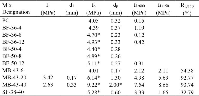
Table 2.2. Flexural testing results Mix
Designation
f1 d1 fp dp fL/600 fL/150 RL/150
(MPa) (mm) (MPa) (mm) (MPa) (MPa) (%)
PC 4.05 0.32 0.15
BF-36-4 4.39 0.37 1.19
BF-36-8 4.70* 0.23 0.12
BF-36-12 4.93* 0.33 0.42
BF-50-4 4.40* 0.28
BF-50-8 4.89* 0.26
BF-50-12 5.11* 0.27 0.31
MB-43-6 4.01 0.17 2.12 2.11 54.38
MB-43-20 3.42 0.17 6.14* 1.30 4.98 5.69 92.77
MB-43-40 2.63 0.33 9.22* 2.00* 7.54 8.66 93.74
SF-38-40 5.28* 0.60 3.33 1.65 32.79
Note: * indicates effect of fibre is significant at 95% confidence interval (see Appendix B for MB specimens and [18] for SF and BF specimens).
The poor post-crack performance of BF (Fig. 2.5) was not surprising given the
lack of visible fibres in the cracked cross-section, as shown in Fig. 2.7. Even at the
highest dosages, BF was not visible by eye, and thus, some level of degradation in the
chopped fibres was suspected. Regardless, the BF increased the first-peak stress, and
therefore, provided some benefit. In most cases, the deflection at the first-peak stress was
found to be lower in BF specimens in comparison with PC (Fig. 2.5 and Table 2.2). This
would suggest the influence of BF is an increase in first-crack strength and modulus of
elasticity as fibre dosage increases. Moreover, the increases are greater with fibers 50 mm
27
increasing first-peak load (Fig. 2.6). In this regard, MB-43-20 specimens had provided a
similar increase as SF-38-40 specimens. Furthermore, MB specimens behaved in a
ductile manner after cracking. As a result, the MB specimens were able to carry between
50% and 90% of peak-load at a deflection of 3 mm (L/150) and still had residual load
capacity at a very large deflection of 10 mm. This is because the MB composites failed
primarily by gradual fibre pull-out, evidenced by the lack of ruptured fibres observed in
the cracked cross-section (Fig. 2.7). The post-cracking performance of MB-43-6
specimens was comparable to that of SF-38-40 (Table 2.2).
2.3.2 Impact Testing
It was found after several preliminary tests that all 24 PC specimens cracked after
a single blow and failed after one additional blow, if not already failed, when using the
full drop height of the hammer (457 mm). A similar performance was observed with five
specimens from all other mix designations (Table 1). Therefore, in the subsequent impact
tests, the height was reduced to 152 mm (6 in.). However, with the reduced
drop-height of 152 mm, the MB-43 and SF-38 specimens required above 100 blows to fail,
which was deemed impractical. Thus, after the first crack was observed in SF-38 and
Fig. 2.7. Cracked cross-section of failed flexural test specimens
28
MB-43 specimens, the hammer was dropped from the full height (457 mm) and
compared with PC subjected to the same impact. Table 2.3 shows the mean number of
blows until the first crack (N1) and subsequent number of blows until failure (N2).
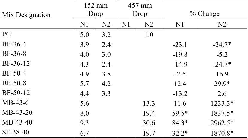
Table 2.3. Impact testing results
Mix Designation
152 mm Drop
457 mm
Drop % Change
N1 N2 N1 N2 N1 N2
PC 5.0 3.2 1.0
BF-36-4 3.9 2.4 -23.1 -24.7*
BF-36-8 4.0 3.0 -19.8 -5.2
BF-36-12 4.3 2.4 -14.9 -24.7*
BF-50-4 4.9 3.8 -2.5 16.9
BF-50-8 5.7 4.2 12.4 29.9*
BF-50-12 4.4 3.3 -13.2 2.6
MB-43-6 5.6 13.3 11.6 1233.3*
MB-43-20 8.0 19.4 59.5* 1837.5*
MB-43-40 9.3 30.6 84.3* 2962.5*
SF-38-40 6.7 19.7 32.2* 1870.8*
Note: * indicates change is significant at 95% confidence interval (see Appendix C)
Statistical analysis was completed with the Mann-Whitney U-test, since it was
unclear if the data followed a normal distribution; something other researchers using the
test method have also reported [12, 13, 19]. The results show BF does not have a
statistically significant influence on first-crack strength (N1) and only in a few cases was
found to significantly influence post-cracking performance (N2). At best, BF-50-8 was
found to increase N2 by approximately 30%. On the other hand, BF-36-4 and BF-36-12
were found to decrease N2 by approximately 25%. It is believed these differences are the
result of an insufficient sample size, since unlike the MB mixes, there was no obvious
trend in the data and the BF was not visible bridging the crack. All of the data is
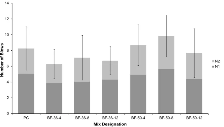
29
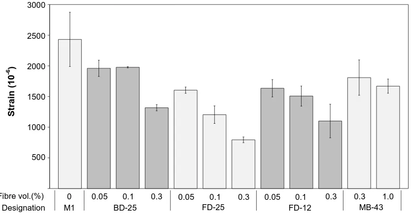
N1 and N2) is depicted. The error bars shown represent one standard deviation on either
side of the measured mean. Based on the size and overlap of the error bars, it can be seen
visually from Fig. 2.8 that the differences in the mean values between PC and BF
specimens are not significant in a practical sense. On the other hand, the differences in
mean values in the MB specimens are clearly significant (Fig. 2.9).
Fig. 2.8. Impact test results of BF specimens
30
The cracked cross-sections shown in Fig. 2.10 are similar to those in Fig. 2.7, in
which fibres are not visible in BF specimens, while fibres in MB specimens are clearly
effective preventing separation by bridging the crack.
An obvious trend in the data is present, where increasing dosages of MB resulted in
increases in N2 ranging from approximately 1200% to 3000% (Table 2.3). MB-43-20
specimens had a similar performance to SF-38-40 specimens, with an increase in
post-cracking impact strength (N2) of approximately 1900%. In both MB and SF specimens,
observation of the cracked cross-section showed nearly all fibres failed by pull-out.
Ruptured fibres were more prevalent in SF specimens, which is likely due to the increase
in bond strength from the hooked ends of the SF. Moreover, MB and SF were also
effective in increasing the crack strength of the concrete (N1). The increase in
first-crack strength of MB-43-20 specimens was similar to that of SF-38-40 specimens.
Although it should be noted that using the full drop-height (457 mm) during preliminary
testing, the MB and SF specimens cracked after no more than two blows. Thus,
first-crack strength under impact loading is likely most dependent on the concrete properties.
Fig. 2.10. Cracked cross-section of failed impact test specimens
31
2.3.3 Interfacial Properties
The scanning electron microscope (SEM) image in Fig. 2.11 (a) shows the
penetration of cement hydration products (likely calcium hydroxide – see Appendix D)
in-between individual filaments of a BF bundle. This could explain the brittle nature of
the BF composites observed in this work, whereby the growth of hydration products
between the filaments increases the fibre-matrix bond strength beyond the tensile strength
of the fibres, resulting in failure governed by fibre rupture. This is further evidenced by
the lack of visible fibres in the failed cross-sections, as shown in Figs. 2.7 (a) and 2.10
(a). Preliminary fibre pull-out testing shows agreement with this idea, since initially the
individual filaments in the bundle failed independently, but after 28 the entire bundle of
filaments failed uniformly (see Appendix E). Moreover, deflection at peak-load is
generally lower in BF-50 specimens than BF-36 specimens (Table 2.2). Thus, failure may
be a combination of pull-out and rupture. In both cases, failure would be due to fibre
rupture; however the 50 mm fibres probably slipped a little less than the 36 mm fibres
due to increased bond strength from a greater contact area with the matrix. The same
phenomenon is often reported in literature related to GFRC [20-22], though it is not
agreed upon if the composites lose toughness primarily due to a physical mechanism, as
suggested in this case, or by a chemical mechanism. In the case of MB specimens, the
polymer appeared to be effective in preventing the penetration of hydration products.
Some cracks were observed in the polymer, as shown outlined in a white broken line in
Fig. 2.11 (b), that are likely the result of mechanical damage during mixing. Pull-out
failure observed during testing would indicate it is unlikely the cracks have a significant
32
longer duration or in harsher mixing conditions. It should be noted the SEM images in
Fig. 2.11 (a) and (b) are of different magnification.
Ongoing work at the University of Windsor has shown BF bundles will abrade
more severely during mixing in the presence of higher quantities of coarse aggregate. Fig.
2.12 shows the typical appearance of the cracked cross-section of a BF-50-12 impact
specimen. Not only could no fibres be found oriented in a manner that would suggest
they were effectively bridging the crack, but the bundles had also clearly been separated
into individual filaments. It is believed this is the result of a combination of abrasion
during mixing and the ongoing growth of hydration products between the filaments. The
work of Bentur [20] found that in brittle composites, spaces between filaments were at
least partially filled with hydration products, while in the case of ductile composites,
these spaces were largely empty. Therefore, future research should address how to
mitigate this issue since ductility is a very desirable trait of FRC.
Fig. 2.11. SEM images of fibres in concrete after 7 days
(a) Bundle dispersion fibre (b) Minibar
33
Jiang et al. [5] observed that the increases in compressive and flexural strength of
BFRC diminished over time and attributed it to fibres de-bonding from the matrix. The
hypothesis was based on the development of spaces between the fibre and matrix and a
decrease in the density of cement on the fibre surface between 7 and 28 days. In some
instances spaces were observed between the fibres and matrix, but it was believed to be
the result of mechanical disruption due to testing or specimen preparation. Changes in
cement density on the fibre surface after 7 and 28 days were not obvious. However,
distinct differences were observed after 9 months. The differences are characterized well
by Figs. 2.13 and 2.14. It can be found in Fig. 2.13 the amount of cement on the fibre
surface appears to decrease. Additionally, as shown in Fig. 2.14, the roughened fibre
surface after 9 months indicates a chemical reaction may have taken place.
34
Scheffler et al. [23] have shown BF corrodes in a cement solution, characterized
by the development of small holes on the fibre surface after 7 days. Previous research has
also shown basalt fibres will lose tensile strength over time when immersed in a solution
of calcium hydroxide intended to replicate a hydrating cement medium [24, 25].
Therefore, the relative poor performance of BF observed in this work is believed to be
Fig. 2.13. Change in cement density on fibre surface over time
(a) After 7 days (b) After 9 months
Fig. 2.14. Change in fibre surface after immersion in concrete
35
analogous to the well-established aging process of GFRC. The aging process of GFRC
has two primary mechanisms: firstly, a physical mechanism characterized by the growth
of hydration products between the filaments, and secondly, a chemical attack due to the
high alkalinity of the cement matrix [26]. This is unsurprising given the similar
manufacturing process and chemical composition of basalt and glass fibres. This research
shows the use of a polymer is effective in overcoming these problems, and thus, MB are a
promising alternative to steel fibres for concrete reinforcement. Although some research
has been done to quantify the long-term durability of BFRP rebar [27], similar work
should be undertaken for MB due to the substantial increase in surface area and the
potential for damage during mixing. Finally, it should be noted that a vast amount of
research exists on mitigating the aforementioned problems with GFRC by the addition of
pozzolanic fillers to ordinary Portland cement concrete mixes, or with the use of
alternative cements [26]. This would likely explain why Dias and Thaumaturgo [6] found
BF performed better in a geopolymer concrete than in Portland cement concrete. Future
research into BFRC can likely be expedited by taking advantage of the parallels drawn
with GFRC and the enormous amount of work already published in that field.
2.4 CONCLUSIONS
The following conclusions are based on the results obtained from this research.
Hence, may be limited to the specimens used in this study.
1. Fibre dosages beyond 12 kg/m3 and 40 kg/m3 of BF and MB, respectively, led to mixing problems due to fibre balling and resulted in difficulty handling, placing,
![Table 1.1 Properties of commonly used fibres [2]](https://thumb-us.123doks.com/thumbv2/123dok_us/1393951.1172070/17.612.107.546.242.497/table-properties-commonly-used-fibres.webp)