Digital Compensation in IQ Modulator Using
H
∞
Optimization—A State-Space Approach
A. G. K. C. Lim
School of Electrical, Electronic and Computer Engineering, University of Western Australia, 35 Stirling Highway, Crawley, WA 6009, Australia
Email:[email protected]
V. Sreeram
School of Electrical, Electronic and Computer Engineering, University of Western Australia, 35 Stirling Highway, Crawley, WA 6009, Australia
Email:[email protected]
G. Wang
School of Electrical, Electronic and Computer Engineering, University of Western Australia, 35 Stirling Highway, Crawley, WA 6009, Australia
Email:[email protected]
Received 30 April 2004; Revised 5 October 2004; Recommended for Publication by Thomas Kaiser
In DSP-based IQ modulators generating CPFSK signals, shortcomings in the implementation of the analog reconstruction filters result in the loss of the constant envelope property of the output CPFSK signal. These ripples cause undesirable spreading of the transmitted signal spectrum into adjacent channels when the signal passes through nonlinear elements in the transmission path and the consequent failure of the transmitted signal in meeting transmission standards requirements. Therefore, digital techniques compensating for these shortcomings play an important role in enhancing the performance of the IQ modulation system. Recently, several methods have been proposed in the literature to digitally compensate for the imperfections in the transfer characteristics of the analog reconstruction filters. Although these methods have been shown to be effective in removing the output envelope ripples, they result in filters of high orders and are therefore computationally demanding to implement on the DSP. Furthermore, previous techniques suffer from numerical instabilities as a result of matrix inversion in the process of calculating the solution vector. In this paper, we present two new techniques for designing the digital compensation filters by means ofH∞optimization to address the limitations of previous solutions. Design of control systems byH∞optimization is now a standard technique. Simulation examples show that these techniques are effective and lead to substantial improvement of the output envelope ripples.
Keywords and phrases:H-infinity optimization, digital compensation, IQ modulators.
1. INTRODUCTION
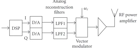
Wireless communications are currently undergoing enor-mous growth and change. Much of the current develop-ment in wireless communication is based on digital com-munication principles. Digital subsystems are used exten-sively to implement radio transceivers [1]. The current trend in software-defined radios is the replacement of as much analog subsections of a radio transceiver as possible with programmable digital hardware [2]. In this paper, we con-sider the use of inphase/quadrature (IQ) modulation in transceiver architecture. A versatile approach to the imple-mentation of an IQ modulator is to synthesize the base-band I and Q signals using a digital signal processor (DSP) fol-lowed by a vector modulator to upconvert the signals directly
into radio-frequency (RF) signals. The IQ modulator struc-ture incorporating DSP is shown in Figure 1. Here, the I and Q channel baseband signals are generated digitally us-ing a DSP and converted into analog signals usus-ing digital-to-analog (D/A) converters and analog reconstruction filters before modulation and transmission.
DSP I
Q D/A D/A
Analog reconstruction
filters LPF1 LPF2
Vector modulator
ωc
RF power amplifier
Figure1: Radio transmitter architecture incorporating digital IQ
modulation.
reconstruction filter frequency responses. In the case of continuous-phase-frequency shift Keying (CPFSK) signals, these shortcomings cause distortion of the I and Q channel signals resulting in the loss of the constant envelope prop-erty of the output CPFSK signal. This can cause significant degradation of the performance of the transmitter system. Ripples in the envelope function cause undesirable spread-ing of the signal spectrum into adjacent channels when the signal passes through a nonlinear RF power amplifier (PA) in the transmitter [3,4].
Digital compensation for the shortcomings in the analog subsystems of quadrature modulators has received consid-erable attention in the literature lately [5,6,7,8,9]. Short-comings in the implementation of the analog subsystems can be classified into two categories, that is, static errors and frequency-dependent transfer characteristics errors. Here, we will consider only the frequency-dependent errors. Exten-sive work has been done on digital predistortion techniques [3,4], which compensate for nonlinearities in the power am-plifier shown in Figure 1in an effort to reduce spreading of the transmitted signal spectrum into adjacent frequency channels. However, most of these techniques ignore the ef-fects of the analog reconstruction filters, and in [4] it is shown that the characteristics of the two analog lowpass fil-ters can significantly reduce the usefulness of some of these techniques.
The principal sources of the frequency-dependent trans-fer characteristics errors are the two analog reconstruction filters. The study of the effect of analog reconstruction filters on the performance of the quadrature modulator has been reported in [3, 4]. Nevertheless, little work has been pre-sented on compensating for the frequency-dependent char-acteristics of the analog reconstruction filters.
In [6], a method was proposed to remove the unwanted ripples at the vector modulator’s output signal envelope us-ing digital signal preshapus-ing filters in the I and Q channels. This is to precompensate for both imbalances in the ana-log reconstruction filters’ frequency responses as well as de-partures from constant magnitude, linear phase in the pass-band of each reconstruction filter. This method employs a least-square (LS) optimization approach where the pre-compensation finite impulse response (FIR) filters are found by minimizing the least-square error of the error transfer function. An alternative solution was given in [7] using state-space approach.
Although these methods have shown to be effective in re-moving the output envelope ripples, they result in FIR filters that have a large number of coefficients and are computa-tionally demanding to implement on the DSP. Furthermore, the method in [6] requires special attention to numerical is-sues in order to achieve good results in practical application. Specifically, the solution matrix to a least-square optimiza-tion problem must first be regularized by discarding eigen-values that are smaller than some threshold value before the solution vector is computed. In [8], a technique is presented to reduce the computational load by increasing tap spacing of the FIR filters and some encouraging results were obtained.
Recently, [9] proposed a digital compensation scheme using infinite impulse response (IIR) filters since IIR filters are known to be able to produce long impulse responses us-ing only a small number of filter coefficients and thus will be useful in such application. These IIR filters are designed us-ing an indirect method, where the filters are obtained from FIR filters using model reduction technique. The method in-volves two steps: first an FIR filter is designed using the opti-mization technique proposed in [6,7]; next a low-order IIR filter is obtained using model reduction technique of [10]. This approach again requires special attention to numerical issues. Otherwise, conversion from an FIR to an IIR filter will produce inconsistent results.
In this paper, we present two state-space approaches for obtaining the digital compensation filters; one results in IIR filters; while the other in FIR filters. These compensation fil-ters are found by minimizing theH∞norm of the error
trans-fer function. Design of control system byH∞minimization
is now a standard technique. The concept of optimal model matching byH∞ optimization has been studied thoroughly
in [11, 12, 13]. Chen and Francis [13] proposed a proce-dure for designing the IIR synthesis filters in multirate fil-ter bank by converting thel2-induced problem to one ofH∞
optimization. Here, the IIR filters are obtained directly from the solution rather than an intermediate FIR solution using the mu-analysis and synthesis toolbox in Matlab. The FIR fil-ters, however, are obtained using the linear matrix inequality (LMI) control toolbox in Matlab.
2. DEFINING THEH∞CONTROL PROBLEM
Figure 2 shows a typical digital precompensation structure [6,7]. The additional components of the digital compensa-tion structure are the two digital filters, that is, F1 and F2. These filters are designed to precompensate for departures from a constant magnitude and phase response (in the pass-bands) of each of the signal reconstruction filters, LPF1 and LPF2, and to achieve gain and phase balance between these two filters. The A/D converters are used to digitize the output signal from the reconstruction filters, so that measurements can be made on the DSP system.
DSP Phase function synthesis
cos
sin F1
F2 D/A
D/A LPF1
LPF2 A/D
A/D modulatorVector Nonlinear RF amplifier ωc
Figure2: IQ modulator and digital precompensation structure.
x(k)
d(k)
D(z)
r(k)
D/A LPF
Filter A/D
h(t)
yr(k) − + +
e(k) y(k)
R(z)
H(z)
Figure3: Generic I or Q channel optimization structure.
desired function [6,7]. The generic I or Q channel optimiza-tion structure is shown inFigure 3.
InFigure 3,D(z) is the nominal desired response,H(z) is the discrete-time equivalent transfer function of the D/A analog reconstruction filter and A/D converter whileR(z) is the transfer function of the compensation filter. In this pa-per, the parameters of the analog reconstruction filter are as-sumed to be known a priori(see [6] for the identification of the analog systems parameters). Our objective is to find a stable transfer function R(z) such that the cascaded sys-tem ofR(z)H(z) closely approximates the desired response D(z) in some sense of error measure. The method proposed in [4] determines the FIR compensation filters by minimiz-ing the least-square error, which is equivalent to minimizminimiz-ing the H2 norm of the error functionD(z)−R(z)H(z)2. If M(z) is a transfer function of a stable, causal LTI system with inputx(k) and outpute(k), then it is well known that the l2-induced norm equals theH∞norm ofM(z) [13], that is,
sup
x2=1
e2= M∞. (1)
Therefore, in this paper, we propose a method for comput-ing the FIR or IIR compensation filters viaH∞optimization.
Hence, we define the objective function as
J= inf sup
R(z)x2=1
e2:=inf
R(z)
D(z)−R(z)H(z)∞. (2)
Then our precisedesign problem statementis as follows.
x
G(z)
e
R(z)
u y
Figure4: The standard block diagram.
Given stable FIR filtersD(z) andH(z), find causal stable digital filter, IIR or FIR,R(z) to minimizeJ.
This quantityJis taken to be the performance measure of the digital compensation. A small value ofJ means that the errore(k) is uniformly small over all inputsx(k). Ideally, we requireJ =0, so that the I and Q channels are perfectly matched. This optimization is over all matricesR(z) that are analytic and bounded outside the unit disc. In Sections3and 4, we present the state-space formulations of the digital IIR and FIR compensation filters, respectively.
3. IIR FORMULATION
In this section, we present the algorithm for finding the I and Q channel digital IIR compensation filters. This algorithm results in low-order IIR filters that are easy to implement, and are able to achieve a substantial reduction in output en-velope ripples. Moreover, these IIR compensation filters are obtained directly based on systems parameters, and not via an intermediated FIR solution as was in the case of [9].
The digital IIR compensation filters are obtained using thehinfsynfunction in Matlab, which uses the formulas de-scribed in Glover and Doyle’s paper [14] for solution to the optimalH∞control design problem. The Matlab programs
forH∞optimization use state-space representations of
trans-fer functions. In this section, we present the state-space for-mulas relevant to the design program. LetD(z) andH(z) be stable systems with the following minimal realizations:
D(z)=
AD BD
CD DD
, H(z)=
AH BH
CH DH
. (3)
Since the Matlab programhinfsynrequires a realization in the form ofFigure 4, we need to convert the generic optimization structure inFigure 3to that inFigure 4. Themodel-matching
problem inFigure 3can be recast as a standardH∞control
problem [12] inFigure 4by defining
G(z)=
D(z) −I H(z) 0
. (4)
Lemma 1. The transfer matrixG(z)has the realization
Proof. Expanding (4) gives
G(z)=
Therefore, we have the relation in (5).
The Matlab function hinfsyn takes in a realization for G(z) as input and outputs a realization ofR(z). The result-ing filterR(z) is an IIR filter with the same order asG(z) that minimizes theH∞norm fromxtoeinFigure 4. Since hin-fsyn works in continuous-time domain, one must perform a bilinear transformation ofG(z) toGc(s), then runhinfsyn
to obtainRc(s), and then perform a bilinear transformation
back to the discrete-time domain to getR(z).
However, the function hinfsyn results in IIR filters of quite high order and are not desirable for practical imple-mentation. It may be possible to get lower-order compen-sation filters if one reduces to minimal realizations at each appropriate stage, that is, if one discards uncontrollable and unobservable states. Another alternative is to reduce the or-der of the resulting IIR filter through model reduction tech-niques. There are a number of techniques available for model reduction. Some of the well-known techniques are balanced truncation [10] and optimal Hankel norm approximation [15]. In this paper, we consider the technique of balanced truncation to obtain a low-order IIR filter. The preceding re-sults can now be summarized in the following algorithm.
Algorithm 1. Summary of IIR Algorithm.
(i) Compute a state-space realization{AG,BG,CG,DG}of the plantG(z)given in(5).
(ii) Use bilinear transformation to transform G(z) into continuous-time domain to obtainGc(s).
(iii) ComputeRc(s)using hinfsyn function in Matlab.
(iv) TransformRc(s)back to discrete-time domain using bi-linear transformation to getR(z).
(v) Use model reduction techniques [10] to eliminate nearly uncontrollable or unobservable states.
Remark1. The two A/D converters are included in the struc-ture such that the unknown analog filters time-domain re-sponseshI(t) andhQ(t) can be measured using the DSP sys-tem. Note that while the A/D converters are used for the iden-tification of the analog reconstruction filter responses, they are not in the transmission path. Therefore, it is important that these components are suitably chosen or are calibrated so that they do not introduce significant scaling or offset er-rors. An effective technique for compensating for the imple-mentation errors such as gain imbalances, I and Q channel DC offset errors and phase errors, has been successfully de-veloped in [16].
4. FIR FORMULATION
In this section, the algorithm for designing the FIR pre-compensation filters is presented. The digital FIR compen-sation filters obtained have low orders and are able to achieve significantly higher ripple reduction factor than previously existing FIR techniques [6,7]. Here, the I and Q channel digital FIR compensation filters are found using LMI theory. In particular, the necessary state-space formulas for solving the design problem in LMI control toolbox in Matlab are de-rived. Consider the following lemma.
Lemma 2. Let
The proof is omitted. Please see [17].
re-where the transfer functions are defined by
From Sections2and3, we know that the error transfer func-tion is given by
E(z)=D(z)−R(z)H(z)=D(z)−H(z)R(z). (12)
Note that the order of the transfer matrices can be in-terchanged because both H(z) and R(z) are linear time-invariant (LTI) systems. The transfer matrixE(z) has a min-imal realization given by
ExpressingR(z) in controllability canonical form [18] yields
AR= It is clear that the only unknowns in the realization in (13) areCRandDR. Therefore, we can use LMIs to minimize D(z)−H(z)R(z)∞.
Algorithm 2. Summary of FIR Algorithm.
(i) Compute state-space matricesAandBusing(13).
(ii) Construct the LMIs using(9)and solve using LMI con-trol toolbox in Matlab.
(iii) Compute the FIR compensation filters using
R(z)=CR
In this section, we present some simulation results to show the effectiveness of the proposed methods. The simulation studies are centred on a single channel ERMES (European Radio Message System) modulation format transmitter [6, 7]. For the results presented inSection 5.1, the two lowpass filters, LPF1 and LPF2 have a nominal 6th, order lowpass characteristic while for the results presented in Section 5.2 the analog filters have nominal 4th, order lowpass character-istic. In both sections, the analog filters have cutofffrequency of 20 kHz, but each response corresponds to particular real-ization of the filter circuit resulting from the perturbations of
0.4
Figure5: I and Q channel digital 20th-order IIR compensation
fil-ters impulse.
the component values about its nominal values. These analog filters are implemented using cascadedSallenandKey 2nd-order sections where the circuit component tolerance is as-sumed to be 5% for resistors and 10% for capacitors. The desired responseD(z) is chosen to have the same magnitude characteristics as the nominal response of the reconstruction filters but constrained to have linear phase. The digital sys-tem sampling frequency is 200 kHz. In the following two sec-tions, we present and compare some results on root mean square (RMS) envelope ripples as a measure of the modula-tor’s performance.
5.1. IIR compensated system
In this subsection, the simulation results of different orders of IIR compensation filters used in compensating for the shortcomings for the analog reconstruction filters are pre-sented. Going back to the standard H∞ control block
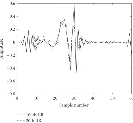
dia-gram inFigure 4, the function hinfsynin Matlab returns a controller R(z) that has the same order as the plant G(z). Based on the lengths of impulse responses chosen forD(z) and H(z), the realization G(z) has an order of 100. Thus, the initial IIR filter obtained is of 100th order, where the nu-merator and denominator polynomials are 100 taps, respec-tively. IIR filters of this high order are not suitable for practi-cal implementation. Therefore, model reduction techniques are employed to reduce the order of the IIR filters.
0.4 0.3 0.2 0.1 0 −0.1 −0.2 −0.3
A
m
plitude
0 10 20 30 40 50 60
Sample number 100th IIR
20th IIR
Figure6: Plot of impulse responses of 100th-order IIR and
20th-order IIR filters in I channel.
channel is plotted on the same graph as the original 100th-order IIR filter. This is to illustrate the effectiveness of model reduction technique in reducing the order of the IIR com-pensation filters. It can be seen that the impulse responses of the reduced 20th-order IIR filters approximate reasonably well the original 100th-order IIR filters.
Table 1summarizes the RMS envelope ripples obtained using different filter order.Table 2shows the RMS ripple val-ues for the IIR compensated system proposed by [9]. The “ripple reduction factor” in Tables1and2are calculated as follows:
ripple reduction factor=uncompensated RMS ripple
compensated RMS ripple
= 3.158 mV
compensated RMS ripple. (16)
It can be seen fromTable 1that low-order IIR filters are still able to provide substantial reduction without signifi-cantly degrading the performance of the modulator. For the original 100th-order IIR filter, a reduction by a factor of ap-proximately 54 is achieved. Since the 57th order is obtained by discarding the uncontrollable and unobservable states, no reduction in ripple reduction factor is observed.
From Tables1and2, it can be seen that the new method outlined in Section 3gives better results in terms of reduc-ing the output envelope ripples. In addition, the technique in [9] requires special attention to numerical issues in order to get a good approximation of the original FIR filter. There-fore, it is difficult to achieve significant order reduction from FIR to IIR. Figure 8shows the output envelope signals for the uncompensated and pre-compensated cases and it is ev-ident that the presence of the 20th- and 15th-order IIR pre-compensation filters still greatly reduces the output envelope ripples.
0.6 0.4 0.2 0 −0.2 −0.4 −0.6 −0.8
A
m
plitude
0 10 20 30 40 50 60
Sample number 100th IIR
20th IIR
Figure7: Plot of impulse responses of 100th-order IIR and
20th-order IIR filters in Q channel.
Table1: RMS envelope ripple for different IIR filter lengths.
IIR filter length RMS envelope Ripple reduction ripple (mV) factor
Uncompensated 3.158 —
100th-order IIR 0.057 54
57th-order IIR 0.057 54
20th-order IIR 0.132 24
15th-order IIR 0.137 23
10th-order IIR 0.251 13
Table2: RMS envelope ripple for different IIR filter lengths using
the method of [9].
IIR filter length RMS envelope Ripple reduction ripple (mV) factor
Uncompensated 3.158 —
20th-order IIR 0.146 22
18th-order IIR 0.242 13
15th-order IIR 0.246 12
5.2. FIR compensated system
1.08 1.04 1 0.96
0 1 2 3 4 5
Time (ms) (a) 1.08
1.04 1 0.96
0 1 2 3 4 5
Time (ms) (b) 1.08
1.04 1 0.96
0 1 2 3 4 5
Time (ms) (c) 1.08
1.04 1 0.96
0 1 2 3 4 5
Time (ms) (d)
Figure8: Envelope functions for the uncompensated and
compen-sated modulator systems: (a) output envelope: uncompencompen-sated, (b) output envelope: compensated 100th-order IIR, (c) output enve-lope: compensated 20th-order IIR, and (d) output enveenve-lope: com-pensated 15th-order IIR.
0.3 0.25 0.2 0.15 0.1 0.05 0 −0.05 −0.1
A
m
plitude
0 5 10 15
Sample number I Channel
Q Channel
Figure9: I and Q channel digital 14th-order FIR compensation
fil-ters impulse responses.
0.5 0.4 0.3 0.2 0.1 0 −0.1 −0.2
A
m
plitude
1 2 3 4 5 6 7 8 9 10 11
Sample number I Channel
Q Channel
Figure10: I and Q channel digital 10th-order FIR compensation
filters impulse responses.
1.04 1 0.96
0 5 10 15
Time (ms) (a)
1.04 1 0.96
0 5 10 15
Time (ms) (b)
1.04 1 0.96
0 5 10 15
Time (ms) (c)
Figure11: Output envelope ripples of the modulator for an
Table3: RMS envelope ripple for different FIR filter lengths.
FIR filter length RMS envelope Ripple reduction ripple (mV) factor
Uncompensated 1.77 —
14th-order FIR 0.25 6.9
10th-order FIR 0.45 3.9
Table4: RMS envelope ripple for different FIR filter lengths using
the method of [7].
FIR filter length RMS envelope Ripple reduction ripple (mV) factor
Uncompensated 1.77 —
18th-order FIR 0.28 6.3
14th-order FIR 0.74 2.4
10th-order FIR 1.52 1.1
It can be seen that the 14th- and 10th-order FIR com-pensation filters are able to provide substantial reduction in output envelope ripples. From the plot of envelope functions inFigure 11, the 10th-order FIR compensated system results in noticeable increase in RMS envelope ripples. Comparing the RMS ripple values in Tables3and4, we can see that the new technique can achieve significantly higher ripple reduc-tion factor than the technique of [7].
Unfortunately, simulation results for higher order of FIR filters are not presented due to the size constraint of the FIR filter. The computational burden of the LMI algorithm in Matlab increases extensively as the order of the FIR fil-ter increases. It is anticipated that higher-order FIR com-pensation filters are able to provide further reduction in RMS envelope ripples thus improving the transmitted sig-nal quality. The use of LMI techniques for designing the compensation filters is still under investigation and will be an ongoing research project. Nevertheless, it is shown that the FIR formulation using LMI techniques is indeed suc-cessful and substantial reduction in RMS envelope ripples is achieved.
6. CONCLUSION
In Sections3and4, we presented two state-space solutions for finding the IIR and FIR compensation filters by solving the H∞ optimization problem. The simulation results in
Section 5 show that substantial improvements in RMS en-velope ripples can be achieved using the algorithms outlined in Sections3and4. These methods are simple and easy to implement using the readily available functions in Matlab, and furthermore the stability of the models is guaranteed. In addition, these methods are able to achieve significantly higher ripple reduction factor compared to the previous ex-isting techniques.
However, there is a disadvantage in using LMI optimiza-tion due to the increase of LMI computaoptimiza-tional load with
increase filter order, and thus higher-order FIR filters could not be tested. Nevertheless, research on LMI optimization is still very active and substantial speedups can be expected in the future.
ACKNOWLEDGMENT
This project was funded by the Australian Research Council (ARC) under Discovery Grant Scheme.
REFERENCES
[1] Z. Kostic and S. Seetharaman, “Digital signal processors in cellular radio communications,”IEEE Communications Mag-azine, vol. 35, no. 12, pp. 22–35, 1997.
[2] T. Hentschel, M. Henker, and G. Fettweis, “The digital front-end of software radio terminals,”IEEE Personal Communica-tions, vol. 6, no. 4, pp. 40–46, 1999.
[3] L. Sundstrom, M. Faulkner, and M. Johansson, “Effects of reconstruction filters in digital predistortion linearizers for RF power amplifiers,” IEEE Trans. Vehicular Technology, vol. 44, no. 1, pp. 131–139, 1995.
[4] S. Leyonhjelm and M. Faulkner, “The effect of reconstruc-tion filters on direct upconversion in a multichannel environ-ment,” IEEE Trans. Vehicular Technology, vol. 44, no. 1, pp. 95–102, 1995.
[5] R. Marchesani, “Digital precompensation of imperfections in quadrature modulators,” IEEE Trans. Communications, vol. 48, no. 4, pp. 552–556, 2000.
[6] J. D. Tuthill and A. Cantoni, “Optimum precompensation filters for IQ modulation systems,” IEEE Trans. Communica-tions, vol. 47, no. 10, pp. 1466–1468, 1999.
[7] A. G. Lim and V. Sreeram, “Optimum digital pre-compensation in IQ modulators using state-space approach,” inProc. 5th International Conference on Optimisation: Tech-niques and Applications (ICOTA ’01), vol. 1, pp. 324–331, Hong Kong, China, December 2001.
[8] G. C. Lee, J. Tuthill, and A. Cantoni, “Efficient implementa-tion of digital compensaimplementa-tion in IQ modulators,” inProc. IEEE 27th International Conference on Acoustics, Speech, and Signal Processing (ICASSP ’02), vol. 3, pp. 2697–2700, Orlando, Fla, USA, May 2002.
[9] E. H. Soh, J. Tuthill, V. Sreeram, and A. Cantoni, “Digital compensation in IQ modulators,” inProc. IEEE Region 10 In-ternational Conference on Electrical and Electronic Technology (TENCON ’01), vol. 1, pp. 213–218, Singapore, August 2001. [10] B. C. Moore, “Principal component analysis in linear systems:
Controllability, observability, and model reduction,” IEEE Trans. Automatic Control, vol. 26, no. 1, pp. 17–32, 1981. [11] M. Green and D. J. N. Limebeer,Linear Robust Control,
Pren-tice Hall, Englewood Cliffs, NJ, USA, 1995.
[12] B. A. Francis,A Course inH∞Control Theory, vol. 88 ofLecture
Notes in Control and Information Sciences, Springer-Verlag, Berlin, 1987.
[13] T. Chen and B. A. Francis, “Design of multirate filter banks by
H∞optimization,” IEEE Trans. Signal Processing, vol. 43, no. 12, pp. 2822–2830, 1995.
[14] K. Glover and J. C. Doyle, “State-space formulae for all sta-bilizing controllers that satisfy anH∞-norm bound and rela-tions to risk sensitivity,” Systems Control Lett., vol. 11, no. 3, pp. 167–172, 1988.
[16] Y.-H. Leung and A. Phillips, “Auto-compensation of quadra-ture modulators,” inProc. 2nd Australian Workshop on Sig-nal Processing Applications (WOSPA ’97), pp. 19–23, Brisbane, Australia, December 1997.
[17] R. E. Skelton, T. Iwasaki, and K. Grigoriadis, A Unified Al-gebraic Approach to Linear Control Design, Taylor & Francis, London, UK, 1998.
[18] T. Kailath, Linear Systems, Prentice-Hall, Englewood Cliffs, NJ, USA, 1980.
A. G. K. C. Lim was born in Kuching, Sarawak, Malaysia. He received the B.S. de-gree with first class honours in electrical and electronic engineering from the Univer-sity of Western Australia, Australia, in 2000. Currently, he is pursuing the Ph.D. degree at the University of Western Australia. His re-search interests include control techniques and signal processing.
V. Sreeram obtained B.S. degree in 1981 from Bangalore University, India, the M.S. degree in 1983 from Madras University, In-dia, and the Ph.D. degree from University of Victoria, Canada, in 1989, all in electri-cal engineering. He worked as a project en-gineer in the Indian Space Research Organi-sation from 1983 to 1985. He joined the De-partment of Electrical and Electronic Engi-neering, University of Western Australia, in
1990, and he is now an Associate Professor. He held visiting ap-pointments at the Department of Systems Engineering, Australian National University, during 1994, 1995, and 1996, and at the Aus-tralian Telecommunication Research Institute, Curtin University of Technology, during 1997 and 1998. His research interests are in control and signal processing.