INFLUENCE OF CHEMICAL COMPOSITION AND PROCESSING
CONDITIONS ON THE INTERSTITIAL CONTENT OF COLD ROLLED
FERRITIC STEELS
C. Capdevila, T. De Cock, F. G. Caballero and C. García de Andrés
Materalia Group, Department of Physical Metallurgy, Centro Nacional de Investigaciones Metalúrgicas (CENIM), Consejo Superior de Investigaciones Científicas (CSIC), Avda. Gregorio del
Amo, 8, E-28040 Madrid, Spain.
Abstract
Determining the content of solute elements in cold-rolled ferritic steels constitutes an important aspect in metallurgy, since the interstitial elements have a harmful effect on the anisotropy properties (i.e. texture) of the final product, usually steel sheets for automotive applications. Both the carbon and nitrogen contents in solid solution depend on the chemical composition and thermomechanical parameters, such as the coiling temperature and the cold reduction degree. In this work, thermoelectric power measurements technique has been applied to study the relation between the process variables such as coiling temperature and cold-rolling reduction, and the amount of interstitial elements in solid solution. It was shown that at high coiling temperatures the value of the thermoelectric power only depends on the carbon content in solid solution, meanwhile at low coiling temperatures, a second contribution should be considered due to the presence of nitrogen in solid solution.
Keywords: steels, thermoelectric properties, cold working
*Manuscript (NOT PDF FILE AT REVISE STAGE)
Introduction
New generation ferritic steels for the automobile industry are designed to optimise deep drawing properties, reducing the sheet thickness at the same time. Therefore, these steels are subjected to a large and complex processing route, which includes hot rolling, coiling, cold rolling and continuous annealing at relatively low temperatures (around 600 ºC). During this final stage, a regeneration of the microstructure (recrystallisation) takes place, accompanied by a texture evolution, leading to a partial recovery of the ductility lost during cold rolling. Through a careful selection of the processing parameters in each stage, the sheet anisotropy can be optimised in order to obtain a final texture that is ideal for deep drawing applications. In particular, the coiling temperature and cold rolling stages are of key importance to the microstructure and texture evolution in later stages.
Several studies [1-3] indicate that the interstitial elements C and N seriously affect the anisotropy properties of the material, since both elements exert a detrimental effect on the texture development of a deep drawing steel when they are in solid solution [4]. So far as is known, the dissolved Al and N play no special role during cold rolling, but strongly influence recovery and recrystallisation on subsequent annealing. During slow heating process the agglomeration of N and Al occurs, which retards structural changes in the steel and modify the resulting texture [5]. There has been some discussion in the literature as to whether true precipitates of AlN are formed or whether only „pre-precipitation clusters‟ occur at dislocations and sub-boundaries [6-7]. As experimental techniques have developed in recent years, the balance of opinion appears to have swung some way towards a true precipitation process [8]. Whatever the precise mechanism, there is agreement that recrystallisation, and, in particular, nucleation, is greatly retarded [9-10].
Previous works reported by Abe and co-workers illustrate how powerful the thermoelectric power (TEP) measurement technique can be to measure the content of interstitials in steels [11-12]. In the present work, the relation between the processing route and the content of interstitial elements is
studied by means of TEP. The high sensitivity to any compositional modification and to the deformation state [13] converts the TEP measurements into a very useful technique for determining the interstitial content prior to the recrystallisation stage, and thus allows us a detailed study of the influence of crucial parameters of the processing route, such as coiling temperature and cold rolling degree.
Materials and Methods
The composition of the steels studied in this work is listed in Table 1. The steels were hot rolled in the austenitic range (soaking temperature of 1250 ºC) with a finish rolling temperature (FRT) of 890 ºC, followed by air-cooling to the coiling temperature (CT). Finally, rolling at room temperature was applied with the cold rolling degree (CR) specified in this table.
For the metallographic analysis, as-cold rolled samples were mounted and polished using standard methods. Subsequently, they were etched with picral, which is known to reveal the presence of carbides in the microstructure [14].
The set-up of the thermoelectric power equipment is given elsewhere [15-17]. The experimental procedure of this technique is as follows: the sample is held between two blocks of a reference metal (a low carbon steel in the present case), between which a temperature difference ΔT=10 ºC is applied. Due to the Seebeck effect, this thermal gradient gives rise to a voltage difference ΔV between sample ends. The apparatus does not give the absolute TEP value of the sample (S*), but a relative TEP (S) in comparison toe the TEP of pure iron at 20 ºC (S0*). S is given by the following relation:
0 * * V S S S T (1)
The measurement of thermoelectric power does not depend on the sample size, which constitutes an important advantage of this technique. Moreover, the measurement process is fast (less than 1 minute) and precise (approximately ± 0.5%). The typical resolution of the equipment is 1 nV/K.
Since analysis of very small sized particles was required (AlN particles), it was decided to produce carbon extraction replicas. Extraction replicas allow examining relatively large areas of a sample in the transmission electron microscope compared to thin foils. Carbon replicas were prepared according to Fukami „two step replica method‟ [18]. Samples were polished in the usual way and then etched with 2%-Nital reagent. A small amount of methyl acetate was dropped and spread on the surface of the specimen. Before the volatilization of the solvent, a cellulose acetate film was laid over the specimen. After a few minutes the film was peeled off from the specimen. Subsequently, to avoid the curling of the material, it was kept for about 30 minutes in an air oven heated to 80ºC. Then, the film was put into a high vacuum chamber to perform carbon deposition. Finally, the cellulose acetate layer was dissolved in a sequence of acetone baths. A copper mesh was used to support carbon replicas which were examined in a JEOL JEM-200 CX transmission electron microscope operating at 200 keV.
Results and Discussion
Picral etching of the samples A, C and F reveals that the cementite exhibits a coarse morphology at high CT temperatures (micrographs Fig. 1(a) and 1(b)). Moreover, the higher carbon content of the steel, the higher amount of precipitates (micrograph Fig. 1(b)). On the other hand, when the CT temperature is decreased, different precipitation behaviour is observed resulting in much finer particles (micrograph Fig. 1(c)). From this metallographic analysis, it can be deduced that the precipitation state of the steels is morphologically similar for the same coiling temperature.
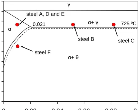
This can be explained in view of the Fe-C phase diagram (Fig. 2), where it can be seen that the solubility temperature of carbon is lower than the coiling temperature in steels A, B, C, D and E. This means that the carbon can migrate towards the grain boundaries and form cementite afterwards [19]. On the other hand, in steel F the coiling temperature is lower than the solubility temperature, which means that the carbon can not be rejected completely during the formation of ferrite and, therefore, the amount of carbon in solid solution ([C]SS) should be higher in this case.
In order to study if the microstructure still contains carbon in solid solution after the cementite precipitation process that takes place during the coiling stage, an isothermal treatment has been performed at 270 ºC during 3 hours. As was already reported in literature [13], at this low temperature only a single process can take place: diffusion of interstitial elements (C and N) towards dislocations. This process leads to an increase of the thermoelectric power value, since the solute atoms that are “pinned” by the dislocations (constituting the so-called Cottrell atmospheres) can no longer be detected by this technique [20].
Table 2 shows changes in the TEP of the reference specimen (S) due to a holding stage at 270 ºC for 3 hours, as well as the average content of carbon in solid solution ([C]SS). The value of [C]SS were
determined based on internal friction measurements. The measurements were performed at Voestalpine Stahl GmbH with the assistance of Dr. Pichler, as part of a European Research Project funded by the European Commission of Coal and Steel [21]. With regard to the quantitative evaluation of the carbon content in solution by internal friction, it is based on the linear relation between the height of the carbon Snoek peak and the carbon content in solution. In this work, the internal friction measurements were performed on an inverted torsion pendulum with an oscillation frequency of about 0.5 Hz employing a heating rate of 50 ºC h-1. They led us to the determination of the logarithmic decrement (δ=πQ-1). Therefore, for a steel with a carbon content in solution equal to [C]SS, δ passes through a maximum (δmax) for a temperature of 40 ºC and it can be obtained that
[C]SS = KQmax-1, where K is a factor which depends on the grain size and on the texture of the alloy.
This factor was determined experimentally from the internal friction spectra measured on the studied steels to have varying carbon contents in solution.
The results listed in Table 2 are consistent with microstructural description of Fig. 1. The content of solute carbon is higher in the steels with low CT temperature (steel F) and with higher nominal carbon content (steels B and C). Moreover, from Table II it can also be concluded that the increase of cold-rolling reduction results in higher values of [C]SS (comparison among steels A, D and E), probably
due to the partial dissolution of cementite during cold rolling.
An increase in TEP value during isothermal holding at 270 ºC is exclusively caused by the diffusion of interstitial elements. The numerical value of this increase can be described by an equation of the following type:
SS N
SS C C K N K S (2)where [C]SS and [N]SS are the C and N content in solid solution, respectively, and KC and KN are two
constants that should be determined.
For the application of this formula, it is required to consider the role of AlN precipitation. In this sense, a first requirement is that the Al and N must be in solid solution before cold rolling. In practice, this means that the soaking temperature before hot rolling has to be sufficiently high to decompose any aluminium nitride present. The solubility product for aluminum nitride reaction in terms of weight percent of the components (indicated by square brackets) is given by [19]:
where T is the absolute temperature. Figure 3(a) shows the relationship between dissolved aluminium and nitrogen at five different temperatures. For the steels studied, with N content between 0.0025 and 0.004 wt.-%, it can be seen that total solution will occur between 900 – 950 ºC for all the steel studied, provided that just the stoichometric amount of aluminium ( 0.01 wt.-%) is present. However, with an aluminium content 0.05 wt.-%, as in the present steels, it is necessary to increase the temperature to
1200 ºC in order to ensure full decomposition of AlN. This is already achieved bearing in mind the soaking temperature of 1200 ºC, but precipitation of AlN must also be prevented during, and immediately after, hot rolling. Leslie et al [9] studied the rate of precipitation, and found a characteristic C-curve with a maximum rate at about 800 ºC (Fig. 3(b)). Thus, to avoid AlN precipitation, it is necessary to cool rapidly between 900 and 600 ºC. In practice, this is achieved by water-spray cooling after hot rolling which is similar to the cooling rate employed to cool down to coiling temperature. However, the coiling process at 740 ºC is a slow process, and thus, it is sensible assumption to consider full AlN precipitation during coiling at this temperature. This assumption is consistent with Meyzaud at al work [10] where AlN precipitation in cold-rolled steels was studied. It was concluded that 90% of AlN precipitation took place after 15 minutes at 700 ºC but took more than 270 hours to reach 50% of precipitation at 550 ºC.
Therefore, samples from steels A, B, C, D, and E where coiling was undergone at 740 ºC present the lowest TEP values. This is consistent with the assumption that most of AlN precipitation events have occurred during the coiling. By contrast, steel F where coiling was undergone at 550 ºC present a higher TEP values which indicate that most of Al and N are still in solid solution in this material. Therefore, in the first case it can be assumed that [N]SS=0 and that the only contribution to the TEP
value is due to the diffusion of carbon.
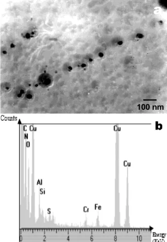
The presence of AlN precipitates was revealed by means of TEM examination of carbon extraction replicas in all the samples listed in Table 1. Meanwhile no identification of AlN precipitates was
possible in steel F it was a successful search in samples coiled at 740 ºC (Fig. 4). From this figure, it seems that the identified precipitates are located along the prior sub-grain boundaries. This result is consistent with other works reported in the literature [22-23].
Effect of carbon content
Figure 5 shows the evolution of TEP variations with values of [C]SS listed in Table 2 for steels A, B
and C. Since the CR values of these three steels are the same, it is a sensible assumption to consider that the density of dislocation is similar. Moreover, as the CT for those steels is 740 ºC, it is likely that most of N is tied up with Al, and hence the TEP variation is solely due to carbon in solid solution. When equation (2) is applied to those steels, it is obtained that KC = 2.34. This value can then be
inserted in the same formula for the subsequent studies.
Effect of cold reduction
The determination of KC value above allows us to analyse the effect of cold-rolling reduction (CR) in
the studied steels. Figure 6(a) shows a comparison between the [C]SS calculated and the ones
measured (Table 2) for steels A, D and E. As can be observed, there is an excellent correlation between the measured and calculated values, which shows that this new method allows remarkable time saving in the determination of the solute carbon content for steels with the same coiling temperature.
Figure 6(b) shows the predicted evolution of [C]SS as cold rolling reduction increases. As it was
mentioned above, the cementite particles break during the cold rolling process, and hence the higher the cold rolling reduction, the higher the carbon content in solid solution.
Effect of coiling temperature
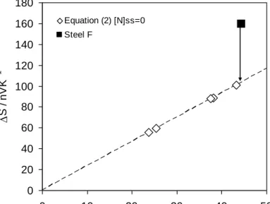
As has been explained before, this reasoning is only valid for steels with high coiling temperature, where no nitrogen is present in solid solution. However, for the case of steel F, the contribution to the TEP value is the sum of the increase due to both C and N diffusion. As can be observed in Fig. 7, the additional increase detected, which is caused by the N diffusion in this steel, makes it possible to calculate the experimental value of KN, assuming that for such a low coiling temperature (CT = 550
ºC) the AlN precipitation is negligible [19]. If all N is in solid solution ([N]ss = 28 ppm), and this is introduced into equation (2), it is obtained that KN = 1.86. This result coincides with a previous study
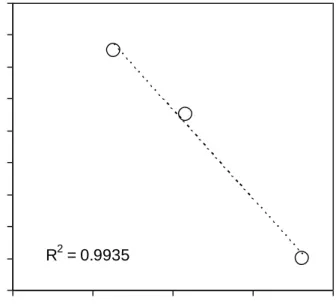
[23-24], in which it is found that the contribution of nitrogen in solid solution is lower than that of C. Finally, the results of the present work can be applied to the study of crystallographic texture. The content of interstitial elements considerably affects the formation of the γ-fibre texture (ferritic grains with <111> direction parallel to the normal direction of the rolling plane), which is the ideal texture for deep drawing applications. From the results of X-ray diffraction analysis, published elsewhere [25], the fractions of grains belonging to this group of crystallographic orientations (fibre), V{111}, can be calculated. When this fraction is compared with the total content of interstitial elements (Fig. 8) in steels A, C and F, it can be clearly observed that the increase of atoms in solid solution considerably decreases the volume fraction of this fibre.
From this study it can be concluded that both an increase of the nominal concentration of carbon, the reduction of the coiling temperature and the increase of the cold rolling degree exert a negative influence on texture and, therefore, on the deep drawing properties of the steel.
Conclusions
The precipitation state of six steels with different C contents, cold rolling reductions and coiling temperatures was analysed. Metallographic etching revealed that the cementite precipitates with coarse morphology in the steels with high coiling temperature and with fine morphology when this temperature is lowered. The thermoelectric power values of these steels were then compared, which leads to the design of a new method to calculate the C content in solid solution. It was shown that at high coiling temperatures the value of the thermoelectric power only depends on the carbon content in solid solution, which increases at higher nominal carbon contents and higher cold rolling degrees. At lower coiling temperatures, a second contribution should be considered, due to the presence of nitrogen in solid solution. With this new model, the relative weight of each process can be quantified in detail. Finally, it was shown that a decrease in the fraction of the ideal texture for deep drawing, the γ-fibre, is directly related to the total content of interstitial atoms.
Acknowledgments
The authors acknowledge the financial support from the European Union through the European Coal and Steel Community programme (ECSC-7210-PR-368) and from the Spanish Ministerio de Ciencia e Innovación (Special Action MAT 2002-10810-E).
References
[1] B. Engl and E.J. Drewes: in „Technology of Continuously Annealed Cold-Rolled Sheet Steel‟, (ed. E. Pradhan), 123-138; 1984, Warrendale, The Metallurgical Society of AIME.
[3] A. Okamoto and M. Takahashi: in „ICOTOM 6: Textures of Materials‟, (ed. S. Nagashima), Vol. 2, 739-748; 1981, Tokyo, The Iron and Steel Institute of Japan.
[4] H. Kubotera, K. Nakaoka, K. Araki, K. Watanabe, A. Nishomoto and K. Iwase: J. Iron. Steel Inst., 1976, 62, 624.
[5] W.B. Hutchinson: Int. Metals Rev., 1984, 29, 25-42. [6] W. Jolley: Metall. Trans., 1972, 3, 245.
[7] R.H. Goodenow: Trans. ASM, 1966, 59, 804.
[8] J.T. Michalak and R.D. Schooner: Trans. AIME, 1968, 242, 1149-1168.
[9] W.C. Leslie, R.L. Rickett, C.L. Dotson and C.S. Watson: Trans. ASM, 1954, 46, 1470-1499. [10] Y. Meyzaud and P. Parnière: Mémoires Scientifiques Rev. Métallurg, 1974, LXXI, 423-434. [11] H.Abe and Tak. Suzuki: Trans. ISIJ, 1980, 20, 690.
[12] H.Abe and Tak. Suzuki: Trans. ISIJ, 1979, 19, 689.
[13] N. Lavaire, J. Merlin and V. Sardoy: Scr. Mater., 2001, 44, 553-559. [14] F.S. Lepera: Journ. of Metals., 1980, 32, 38-39.
[15] C. Capdevila, F. G. Caballero and C. G. de Andres: Scr. Mater., 2001, 44, 593-600.
[16] F. G. Caballero, C. Capdevila, L. F. Alvarez and C. G. de Andres: Scr. Mater., 2004, 50, 1061-1066.
[17] F. G. Caballero, C. Capdevila and C. G. de Andres: Mat. Sci. Technol., 2001, 17, 1114-1118. [18] A. Fukami: in „Specimen Preparation Techniques for Electron Microscopy‟, 5-7, 1967, Tokyo, Jeol News.
[19] W. B. Hutchinson and K. Ushioda: Scand. J. Metall., 1984, 13, 269-275.
[21] W. B. Hutchinson, L. Ryde, T. Iung, T. De Cock, C. Capdevila, F. G. Caballero, C. Garcia de Andres, J. Sperl, M. Bartieri, L. Alleva and M. Buccioni: in „Development of High Strength Steel Products by Back Annealing‟, 47, 2006, Brussels, European Commission.
[22] J.P. Ferrer, T. De Cock, C. Capdevila, F.G. García Caballero and C. García de Andrés: Acta
Mater., 2007, 55, 2075-2083.
[23] C. Capdevila, J. P. Ferrer, F. G. Caballero and C. G. De Andres: Metall. Mater. Trans. A, 2006, 37A, 2059-2068.
[24] A. Brahmi: in „Etude de la precipitation des carbures de fer en presence du manganese et du nitrude d‟aluminium dans les aciers extra-doux par mesure du pouvoir thermoelectrique‟, (Doctoral Thesis), 212, 1993, Lyon, L‟Institut National des Sciences Appliquees de Lyon – INSA.
[25] T. De Cock, C. Capdevila, F.G. Caballero and C. García de Andrés: Mater. Sci. Eng. A, 2009, A519, 9-18.
Tables:
Table 1. Chemical composition (in wt %) and processing variables of the studied steels. CT stands for coiling temperature in ºC, and CR stands for cold-rolling reduction in %.
C Si Mn P Al N CT CR A 0.014 0.007 0.19 0.007 0.055 0.0025 740 70 B 0.045 0.010 0.19 0.012 0.040 0.0037 740 75 C 0.080 0.011 0.17 0.004 0.053 0.0040 740 75 D 0.014 0.007 0.19 0.007 0.055 0.0025 740 59 E 0.014 0.007 0.19 0.007 0.055 0.0025 740 80 F 0.014 0.006 0.21 0.007 0.053 0.0028 550 75
Table 2. TEP variations (ΔS) after a holding stage at 270 ºC during 3 hours and average carbon content in solid solution ([C]SS).
Sample ΔS (nV/K) [C]SS (ppm) A 61 25.4 B 87 38.1 C 102 43.3 D 54 23.7 E 97 37.6 F 159 44.5
Figure Captions:
Figure 1. Microstructure in the as-cold rolled condition of (a) steel A; (b) steel C, and (c) steel F. The cementite particles can be clearly distinguished.
Figure 2. Phase diagram of the low carbon steels, indicating the coiling temperatures of steels studied.
Figure 3. (a) Plot of solubility product fro AlN in austenite at various temperatures, and (b) TTT diagram for AlN precipitation in steel (after Leslie et al. [9]).
Figure 4. (a) Alignment of AlN precipitates and (b) XEDS spectrum.
Figure 5. Comparison between the experimental [C]SS values (Table II) and calculated values of S
(equation (2)) in steels A, B and C.
Figure 6. (a) Comparison between measured (Table II) and calculated (equation (2)) [C]SS values in
steels A, B and C, and (b) prediction of [C]SS evolution with cold rolling reduction (CR).
Figure 7. Increase of the TEP value to the higher solute carbon content in steel F, where an additional increase is detected due to the nitrogen in solid solution.
Figure 8. Evolution of the fraction of γ-fibre grains in function of the total content of interstitial elements in steels A, C and F.
Figure 1. Microstructure in the as-cold rolled condition of (a) steel A; (b) steel C, and (c) steel F. The cementite particles can be clearly distinguished.
(b)
(a)
(c)
Non-colour figure
Figure 2. Phase diagram of the low carbon steels, indicating the coiling temperatures of steels studied.
0
100
200
300
400
500
600
700
800
900
1000
0
0.02
0.04
0.06
0.08
0.1
γ α+ γ α α+ θ 725ºC 0.021 Carbon (weight-%) Temperature ( ºC) steel F steel A, D and E steel C steel B0
100
200
300
400
500
600
700
800
900
1000
0
0.02
0.04
0.06
0.08
0.1
γ α+ γ α α+ θ 725ºC 0.021 Carbon (weight-%) Temperature ( ºC) steel F steel A, D and E steel C steel BCarbon / wt.-%
Temperatu
re
/
ºC
725 ºC 0.021(a)
(b)
Figure 3. (a) Plot of solubility product fro AlN in austenite at various temperatures, and (b) TTT diagram for AlN precipitation in steel (after Leslie et al. [9]).
0 0.02 0.04 0.06 0.08 0.1 0 0.002 0.004 0.006 0.008 0.01 [N] / wt-% [A l] / w t-% 900 ºC 950 ºC 1000 ºC 1050 ºC 1100 ºC Stoichiometric ratio 400 500 600 700 800 900 1000
1.E+00 1.E+01 1.E+02 1.E+03 1.E+04 1.E+05 1.E+06 Time / s T e m p e ra tu re / º C
Start of AlN precipitation End of AlN precipitation
CT=740 ºC
Figure 5. Comparison between the experimental [C]SS values (Table II) and calculated values of S
(equation (2)) in steels A, B and C.
y = 2.3367x R2 = 0.9913 0 20 40 60 80 100 120 20 25 30 35 40 45 [C]SS / ppm S / n V K -1
(a)
(b)
Figure 6. (a) Comparison between measured (Table II) and calculated (equation (2)) [C]SS values in
steels A, B and C, and (b) prediction of [C]SS evolution with cold rolling reduction (CR). 20 25 30 35 40 45 20 25 30 35 40 45 Measured [C]SS / ppm C a lcu la te d [ C ] SS R2=0.96 20 25 30 35 40 45 50 60 70 80 90 CR reduction / % C a lcu la te d [ C ] SS / p p m
Figure 7. Increase of the TEP value to the higher solute carbon content in steel F, where an additional increase is detected due to the nitrogen in solid solution.
0 20 40 60 80 100 120 140 160 180 0 10 20 30 40 50 [C]SS / ppm S / n V K -1 Equation (2) [N]ss=0 Steel F
Figure 8. Evolution of the fraction of γ-fibre grains in function of the total content of interstitial elements in steels A, C and F.
R2 = 0.9935 74 76 78 80 82 84 86 88 90 92 0 20 40 60 80 [C]ss + [N]ss / ppm V {1 1 1 } / %

![Figure 5. Comparison between the experimental [C] SS values (Table II) and calculated values of S (equation (2)) in steels A, B and C](https://thumb-us.123doks.com/thumbv2/123dok_us/11046745.2991905/20.918.276.651.127.411/figure-comparison-experimental-values-table-calculated-values-equation.webp)