ORIGINAL ARTICLE
Chatter model for enabling a digital twin in machining
Shukri Afazov1&Daniele Scrimieri2Received: 15 April 2020 / Accepted: 1 September 2020
#The Author(s) 2020 Abstract
This paper presents the development of a new chatter model using measured cutting forces instead of a mathematical model with empirical nature that describes them. The utilisation of measured cutting forces enables the prediction of real-time chatter conditions and stable machining. The chatter model is validated using fast Fourier transform (FFT) analyses for detection of chatter. The key contribution of the developed chatter model is that it can be incorporated in digital twins for process monitoring and control in order to achieve greater material removal rates and improved surface quality in future industrial applications involving machining processes.
Keywords Digital twin . Chatter model . Cutting forces
1 Introduction
Chatter modelling in machining dates from the 1960s when Tlusty and Polacek [1] and Tobias [2] presented chatter models in machining. Later, Altintas and Budak [3] developed a chatter model with dynamic uncut chip thickness by solving the equation of motion analytically in the frequency domain. Further chatter models considering velocity-dependent damping and cutting forces, as well as run-out effects, have been solved in the time domain using numerical integration [4]. The challenge in all developed chatter models is that the cutting force model needs to accurately predict the actual cut-ting forces which depend not just on the cutcut-ting parameters but also on the cutting tool geometry, frictional conditions, kinematics of the cutting tool and workpiece material state [5]. For instance, the geometry of the cutting edge changes due to wear and the frictional conditions can change too. The workpiece material might have different properties in different locations due to differences in the material microstructure. All
these factors introduce uncertainties for the accurate predic-tion of the cutting forces and create challenges in using existing chatter models in process monitoring and control.
The use of process damping at low spindle speeds has been widely used in the past as well as the design of machine tools with enhanced damping capabilities [6]. Chatter avoidance has been approached by structural modification of tool-holder ge-ometry in order to change the structural dynamics as well as tuning the mass of the tool-holder assembly [7]. Measured cutting forces, accelerations and acoustic emissions have been widely used for process monitoring and control. The most widely used methods are the conversion of measured signals from the time domain into the frequency domain for detection of chatter [8]. Other researchers used the root mean square value in the time domain to identify chatter [9]. Despite the fact that those methods are reliable, they are dimensionless indicators for chatter detection and lack the ability to quantita-tively predict how conservative or aggressive the machining process is. Therefore, a new chatter model is developed and validated in this paper in order to enable the prediction of chatter-free cutting conditions based on measured cutting forces in micro-milling. The coupling of real-time measured cutting forces and physics-based predictive model for chatter-free micro-milling can be considered as a key enabler for the development of digital twins for automated process monitoring and control in micro-milling and other machining processes as well. This could be a step forward in addressing the industrial challenges in implementation of digital twin models in manufacturing operations [10].
* Shukri Afazov [email protected]
1 Department of Engineering, School of Science and Technology, Nottingham Trent University, Nottingham NG11 8NS, UK 2
Department of Computer Science, University of Bradford, Bradford BD7 1DP, UK
https://doi.org/10.1007/s00170-020-06028-9
The paper first discusses the digital twin as a concept for automated process monitoring and control to increase process efficiency. The paper then presents a chatter model using mea-sured cutting forces as an enabler for the digital twin. The validation of the chatter model for micro-milling is finally presented as well as its role in the digital twin.
2 Digital twin for process monitoring
and control: a concept
A digital twin can be described as an organised collection of physics-based methods and advanced analytics that is used to model the present state of every asset (e.g. a machine). By additionally considering the data streams of these assets and communicating with them, it can be considered as a digital counterpart to physical reality. Wherever a physical asset ser-vices a need (for example, moving people from one place to another, electricity provision, manufacturing a product), a vir-tual counterpart can be created to plan, optimise and control it. A wide range of digital twin applications was presented by Cimino et al. [11].
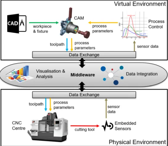
Figure1shows a digital twin concept for process monitoring and control in machining. The digital twin consists of a digital environment, which is a replica of the physical environment,
interfaced with a middleware that facilitates connectivity and the transfer and storage of data, information and knowledge. Considering the manufacture of a component as an asset, the first step is to design it for machining, including the design of the fixture. Once the design is completed, the computer-aided design (CAD) models for the component, fixture and cutting tools are used in a computer-aided manufacturing (CAM) sys-tem to identify the toolpath for specified process parameters. The process parameters can be selected based on knowledge of the specific cutting tool and workpiece material or based on physics-based predictive models. After the toolpath is created in the CAM system, the computer numerical control (CNC) centre is instructed how to operate through the use of G-code and initial referencing. One of the key moments in the digital twin is to identify what data needs to be collected through embedded sensors and how to use it in order to increase the material removal rate and machined surface quality through the use of adaptive process parameters and toolpath regeneration. In the proposed digital twin, measured cutting forces are used to predict chatter-free process parameters through the use of a new chatter model presented in this paper. The new chatter model is the enabler for the proposed digital twin because it can be embedded in process control systems to predict stable machin-ing parameters and achieve increased material removal rates and improved quality of the machined components.
Fig. 1 A digital twin concept for process monitoring and control in chatter-free machining
3 Chatter methodology
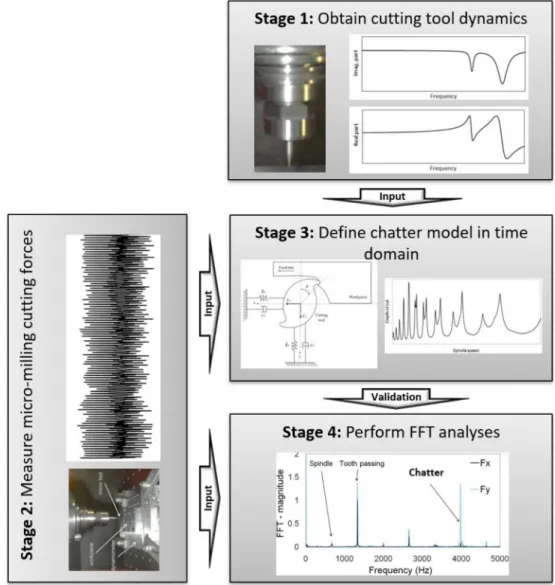
Figure2depicts the four stages of the chatter methodology that was employed in this research to define and validate the proposed model. In stage 1, the dynamics of the tool-holder-spindle assembly is obtained. A tool-holder-tool-holder-spindle assembly for TiN-coated two-flute end-milling tungsten cutting tool with diameter of 500μm and flute length of 1 mm attached to a KERN milling machine was adopted from Afazov et al. [12]. The adopted modal dynamic parameters are natural fre-quency (wn) of 4035 Hz, modal damping (ζ) of 0.016 and
modal dynamic stiffness (k) of 2.1415 MN/m. In stage 2, the micro-milling cutting forces are obtained. Cutting tools with the same coating and overall dimensions were used. The micro-milling cutting forces for AISI4340 with hardness of 31HRC obtained by Afazov et al. [13] and Afazov et al. [14] were used.
In stage 3, the micro-milling chatter model with a time domain solution developed by Afazov et al. [12] is modified
in this research to accommodate the use of measured cutting forces instead of using an empirical cutting force model. The dynamics for two degree of freedom system can be described by the equation of body motion given by Eq. (1).
:: x tð Þ ¼w2n;xFx kx −2ζxwn;x ˙ x tð Þ−w2 n;xx tð Þ :: y tð Þ ¼w 2 n;yFy ky −2ζywn;y ˙ y tð Þ−w2n;yy tð Þ ð1Þ
whereFxandFyare measured milling cutting forces in the x and the y direction respectively. The fourth order of precision Runge-Kutta numerical integration method is employed to solve Eq. (1) in the time domain solution using the same modal dynamic parameters in the x and y directions. The forces at each time increment are obtained by linear interpo-lation between two measured force values. After the cutting tool displacements in the x and y directions are calculated by Eq. (1), statistical variances are employed as a criterion for
Fig. 2 Chatter methodology— definition and validation
detecting the chatter phenomenon. The statistical variances are given by:
S2 x¼ ∑n i¼1 xi−x 2 n−1 ;S 2 y¼ ∑n i¼1 yi−y 2 n−1 ð2Þ
whereS2xandS2yare statistical variances in the x and y direc-tions,xiandyiare the displacements at the corresponding time computed from Eq. (1),nis the number of time increments andxand yare the averaged displacements in the x and y directions. The micro-milling cutting is considered unstable when one of the statistical variances is greater than the value of 1μm2(S2y>1 μm2or (S2y>1 μm2).
Chatter stability is predicted for measured cutting force signals. In stage 4, the same measured cutting forces were processed using the fast Fourier transforms (FFT) to detect chatter in the cutting tool at its natural frequency of approxi-mately 4 kHz. The results from the FFT analyses were used to validate the proposed chatter model.
4 Results
All cutting force measurements used in this research have been obtained on the 5-axis KERN machine with mounted Kistler dynamometer 9258C2 published in [13,14]. Two sets of data were used in this study. The first set of data is produced using
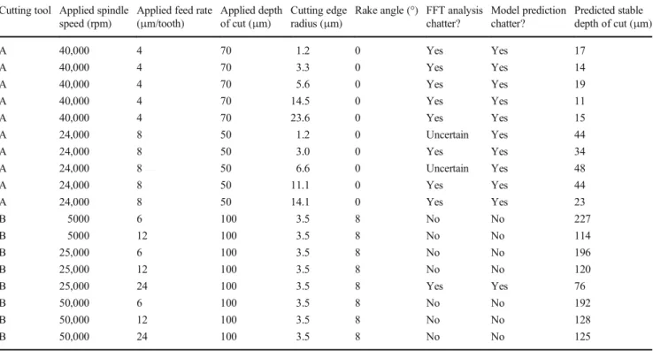
TiN-coated two-flute end-milling tungsten cutting tool with di-ameter of 500μm and flute length of 1 mm with measured rake angle of 0° and cutting edge radius in the range of 1.2–24μm at different wear stages [14], referred to as cutting tool A in Table1. The second set of data is generated for a cutting tool with the same coating and overall geometrical dimensions but with a rake angle of 8° and a cutting edge radius of 3.5μm [13], referred to as cutting tool B in Table1. The measured cutting forces were used to predict the existence of chatter as well as a stable depth of cut. The stable depth of cut was predicted by linearly scaling the cutting forces up when no chatter was pre-dicted or scaling them down if chatter was prepre-dicted. It needs to be noted that the scaling up assumes linear increase of the cut-ting forces due to increase of the cutcut-ting depth. In the event of chatter, the measured cutting forces would capture the dynamic effects and their scaling down would still account for them, which can introduce some error in the prediction.
The results in Table1show agreement between predicted chatter conditions with the proposed chatter model and chatter detection using FFT analyses. Most notable is the uncertain chatter condition for cutting tool A with the FFT analyses which is a subjective decision based on the observation that a vibration is evitable at the cutting tool natural frequency but it is not entirely conclusive that the vibration is sufficient to generate chatter. For all the uncertain conditions detected with the FFT analyses, the chatter model predicted chatter with close predicted stable depths of cut to the applied depth of cut in the experimental trials (i.e. 48μm predicted stable depth
Table 1 Process parameters and chatter results Cutting tool Applied spindle
speed (rpm)
Applied feed rate (μm/tooth)
Applied depth of cut (μm)
Cutting edge radius (μm)
Rake angle (°) FFT analysis chatter? Model prediction chatter? Predicted stable depth of cut (μm) A 40,000 4 70 1.2 0 Yes Yes 17 A 40,000 4 70 3.3 0 Yes Yes 14 A 40,000 4 70 5.6 0 Yes Yes 19 A 40,000 4 70 14.5 0 Yes Yes 11 A 40,000 4 70 23.6 0 Yes Yes 15 A 24,000 8 50 1.2 0 Uncertain Yes 44 A 24,000 8 50 3.0 0 Yes Yes 34 A 24,000 8 50 6.6 0 Uncertain Yes 48 A 24,000 8 50 11.1 0 Yes Yes 44 A 24,000 8 50 14.1 0 Yes Yes 23 B 5000 6 100 3.5 8 No No 227 B 5000 12 100 3.5 8 No No 114 B 25,000 6 100 3.5 8 No No 196 B 25,000 12 100 3.5 8 No No 120 B 25,000 24 100 3.5 8 Yes Yes 76 B 50,000 6 100 3.5 8 No No 192 B 50,000 12 100 3.5 8 No No 128 B 50,000 24 100 3.5 8 No No 125
of cut versus uncertain condition with FFT analysis at 50μm applied depth of cut).
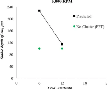
Figures3,4and5show a comparison between predicted stable depths of cut using the proposed chatter model and chatter conditions determined by the FFT for the cutting tool B. It can be seen that both approaches agree, particularly the results at 25,000 RPM in Fig.4. It can be also seen that the stable depth of cut decreases by increasing the feed per tooth due to the increase of the cutting forces.
The advantage of this chatter model is that all geometrical changes of the cutting tool due to wear and change of friction-al conditions, as well as dynamic run-out and materifriction-al prop-erties of the workpiece, can be captured in the measured cut-ting forces. This can enable the realisation of a digital twin for process monitoring and control where a physics-based pdicted model can be incorporated to increase the material re-moval rate in chatter-free machining. The model can be
applied to any material and machine tool. As most of the chatter models are more accurate for ductile materials (e.g. metals) due to the relative accuracy in the predictability of the cutting forces, this chatter model could have success in the accurate stability prediction of brittle materials (e.g. ce-ramics and composites) due to its use of measured cutting forces where discontinuities could be captured as well.
5 Conclusions
The following conclusions are derived from this research: & a new chatter model using measured micro-milling cutting
forces was developed and validated using FFT analyses; & a digital twin concept for process monitoring and control
was presented to illustrate how the new chatter model can enable its realisation;
& the presented digital twin concept for process monitoring and control will be demonstrated on an industrial use case in a future research;
& a comparative study between the proposed chatted model and existing chatter models will be conducted as a future research for better understanding their respective advan-tages and disadvanadvan-tages.
Open Access This article is licensed under a Creative Commons Attribution 4.0 International License, which permits use, sharing, adap-tation, distribution and reproduction in any medium or format, as long as you give appropriate credit to the original author(s) and the source, pro-vide a link to the Creative Commons licence, and indicate if changes were made. The images or other third party material in this article are included in the article's Creative Commons licence, unless indicated otherwise in a credit line to the material. If material is not included in the article's Creative Commons licence and your intended use is not permitted by statutory regulation or exceeds the permitted use, you will need to obtain Fig. 5 Comparison of predicted and FFT stability at 50,000 RPM
Fig. 4 Comparison of predicted and FFT stability at 25,000 RPM Fig. 3 Comparison of predicted and FFT stability at 5000 RPM
permission directly from the copyright holder. To view a copy of this licence, visithttp://creativecommons.org/licenses/by/4.0/.
References
1. Tlusty J, Polacek M (1963) The stability of machine tools against self excited vibrations in machining. In: Proceedings of the ASME international research in production engineering conference, Pittsburg, PA, pp 465–474
2. Tobias SA (1965) Machine tool vibration (trans: Burton AH). Blackie and Sons, Glasgow
3. Altintas Y, Budak E (1995) Analytical prediction of stability lobes in milling. CIRP Ann Manuf Technol 44(1):357–362
4. Quintana G, Ciurana J (2011) Chatter in machining processes: a review. Int J Mach Tools Manuf 51(5):363–376
5. Cheng K (2009) Machining dynamics: fundamentals, applications and practices. Springer, London
6. Altintas Y (2012) Manufacturing automation: metal cutting me-chanics, machine tool vibrations, and CNC design, 2nd edn. Cambridge University Press
7. Gibbons T, Ozturk E, Xuc L, Sims N (2020) Chatter avoidance via structural modification of tool-holder geometry. Int J Mach Tools Manuf 150:103514
8. Lauro CH, Brandão LC, Baldo F, Reis RA, Davim JP (2014) Monitoring and processing signal applied in machining processes –a review. Measurement 58:73–86
9. Ye J, Feng P, Xu C, Ma Y, Huang S (2018) A novel approach for chatter online monitoring using coefficient of variation in machin-ing process. Int J Adv Manuf Technol 96(1–4):287–297
10. Melesse T, Pasquale V, Riemma S (2020) Digital twin for machin-ing tool condition prediction. Procedia Manuf 42:267–272 11. Cimino C, Negri E, Fumagalli L (2019) Review of digital twin
applications in manufacturing. Comput Ind 113:103130
12. Afazov S, Ratchev S, Segal J, Popov A (2012) Chatter modelling in micro-milling by considering process nonlinearities. Int J Mach Tools Manuf 56:28–38
13. Afazov S, Ratchev S, Segal J (2010) Modelling and simulation of micro-milling cutting forces. J Mater Process Technol 210(15): 2154–2162
14. Afazov S, Zdebski D, Ratchev S, Segal J, Liu S (2013) Effects of micro-milling conditions on the cutting forces and process stability. J Mater Process Technol 213(5):671–684
Publisher’s note Springer Nature remains neutral with regard to jurisdic-tional claims in published maps and institujurisdic-tional affiliations.