University of Southampton Research Repository
ePrints Soton
Copyright © and Moral Rights for this thesis are retained by the author and/or other
copyright owners. A copy can be downloaded for personal non-commercial
research or study, without prior permission or charge. This thesis cannot be
reproduced or quoted extensively from without first obtaining permission in writing
from the copyright holder/s. The content must not be changed in any way or sold
commercially in any format or medium without the formal permission of the
copyright holders.
When referring to this work, full bibliographic details including the author, title,
awarding institution and date of the thesis must be given e.g.
AUTHOR (year of submission) "Full thesis title", University of Southampton, name
of the University School or Department, PhD Thesis, pagination
UNIVERSITY OF SOUTHAMPTON
FACULTY OF ENGINEERING AND THE ENVIRONMENT
Institute of Sound and Vibration Research
IMPROVED TURBOFAN INTAKE LINER DESIGN
AND OPTIMIZATION
by
Prateek Mustafi
Thesis for the degree of Doctor of Philosophy
UNIVERSITY OF SOUTHAMPTON ABSTRACT
FACULTY OF ENGINEERING AND THE ENVIRONMENT Institute of Sound and Vibration Research
Doctor of Philosophy
IMPROVED TURBOFAN INTAKE LINER DESIGN AND OPTIMIZATION
by Prateek Mustafi
In modern turbofan engines, fan noise is one of the principle noise sources due to increased bypass ratio of the engines. Acoustic liners in the intake and bypass sections of the engine are effective in mitigating noise generated by the fan. They also play an important role in reducing fan blade instabilities by minimizing low-frequency acoustic reflections within the intake. Any damage on the lined surface has the potential to compromise the effectiveness of the liner; especially, its noise suppressing capabilities. The research presented in this thesis explores these areas on a much wider scale and aims to obtain an improved design of turbofan liners. The work performed ranges from developing an efficient strategy to optimize intake liners automatically to reduce both community noise and low-frequency acoustic reflections, to investigating the effects of liner damage and repair on the performance of zero-splice intake liners.
Computational Aero-Acoustic (CAA) models have been used to predict radiated noise from a turbofan intake and the results have been validated against Rolls-Royce rig and engine test data. Adjustments have been made to the linear predictions to account for non-linear propagation effects which are significant at high fan speeds. Intake liners have been optimised to mitigate radiated noise in the far-field by using the CAA code within automated optimisation routines. The cumulative process time of these automated techniques seems to be within the acceptable limit by the industry. The acoustic effects of liner damage and repair on liner performance have been assessed by using analytical and computational prediction models. The effects of the extent and the location of the damage or the repaired surface on the overall performance of the liner is assessed. Some preliminary rules and guidelines have also been proposed in order to quantify the acoustic effects of the damage.
The acoustic impact of different intake liners on low-frequency reflections have been investigated by using computational models. The results show that high resistance liners are more effective in minimizing acoustic reflections within the intake.
Contents
Abstract iii
List of Figures ix
List of Tables xv
DECLARATION OF AUTHORSHIP xvii
Acknowledgements xix
Abbreviations xx
Symbols xxiii
1 Introduction 1
1.1 Background . . . 1
1.2 Aircraft noise sources. . . 2
1.3 Aims, motivation and original contributions . . . 4
1.4 Report overview . . . 6
1.5 Planning and progress . . . 6
2 Linear prediction method for fan noise propagation and radiation 9 2.1 Introduction. . . 9
2.2 Literature Review . . . 9
2.3 Acoustic propagation model . . . 11
2.3.1 Impedance boundary conditions . . . 12
2.3.2 Sound propagation in a uniform duct with uniform mean flow . . 12
2.3.2.1 Cut-on frequency . . . 15
2.4 CAA prediction tool - ACTRAN/TM . . . 15
2.4.1 The FE formulation . . . 15
2.4.2 Infinite elements . . . 18
2.5 Shell codes to perform intake predictions. . . 19
2.5.1 ANPRORAD . . . 19
2.5.2 PHOENIX . . . 21
2.5.3 Comparison of PHOENIX and ANPRORAD intake predictions . 24 2.6 Summary . . . 25
vi CONTENTS
3 Non-linear propagation of shock waves in turbofan intakes 27
3.1 Introduction. . . 27
3.2 Literature Review . . . 28
3.3 Non-linear wave equation . . . 29
3.4 Nonlinear attenuation of a regular sawtoothtype shock waveform -analytical model . . . 32
3.5 Application of the analytical models to the non-linear propagation of rotor locked BPF tones . . . 36
3.5.1 Non-linear adjustments to linear predictions . . . 37
3.5.2 Application . . . 38
3.6 Summary . . . 40
4 Validation of CAA predictions for forward-arc fan noise 41 4.1 Introduction. . . 41
4.2 Literature Review . . . 42
4.3 Comparison between predicted and measured rig data . . . 43
4.3.1 Intake rig . . . 43
4.3.2 Mode detection data . . . 44
4.3.3 ACTRAN/TM model . . . 45
4.3.4 Noise source model . . . 45
4.3.5 Source representation at subsonic fan-tip speeds . . . 45
4.3.6 Source representation at supersonic fan-tip speeds . . . 47
4.3.7 Comparison of predicted and measured field shapes. . . 49
4.3.7.1 Predicting the non-linear propagation of the rotor-locked mode m=24 . . . 51
4.4 Comparison between predicted and measured engine data . . . 55
4.4.1 Intake geometry and FE mesh . . . 55
4.4.2 Mode detection data . . . 56
4.4.3 Noise source model . . . 56
4.4.4 Comparison of predicted and measured field shapes. . . 58
4.5 Conclusions . . . 60
5 Automated optimisation of intake liners to reduce forward-arc fan noise 61 5.1 Introduction. . . 61
5.2 Literature Review . . . 61
5.3 Liner model . . . 63
5.4 Noise source model . . . 64
5.5 Optimisation study . . . 64
5.5.1 Cost function . . . 65
5.5.2 Automated optimisation schemes . . . 65
5.5.2.1 Scheme 1: Smart Optimisation For Turbomachinery (SOFT) . . . 65
5.5.2.2 Scheme 2: Optimisation toolbox ‘Optimtool’ in MATLAB 67 5.6 Optimisation of intake liners for broadband noise at approach condition 69 5.6.1 High frequency approximation . . . 69
5.6.1.1 Results: Scheme 1 . . . 71
CONTENTS vii
5.6.2 Frequency characteristics of liner attenuation . . . 75
5.7 Optimisation of intake liners for a typical noise spectra at sideline condition 76 5.7.1 High frequency approximation . . . 77
5.7.2 Liner optimisation for broadband source . . . 78
5.7.3 Liner optimisation for BPF tones . . . 78
5.7.4 Liner optimisation for the total noise spectrum - Broadband and BPF tones. . . 81
5.7.4.1 Non-linear adjustments to ACTRAN/TM predictions . 83 5.8 Comparison of the results with the benchmark optimisation studies of Lafronza . . . 86
5.9 Conclusions . . . 87
6 Liner damage study - analytical asymptotic model 89 6.1 Introduction. . . 89
6.2 Literature Review . . . 90
6.3 The liner patch problem . . . 90
6.3.1 Prediction tool . . . 90
6.3.2 Intake geometry, source and conditions. . . 92
6.3.3 Results . . . 93
6.3.3.1 Results at different frequencies . . . 95
6.3.3.2 Results for different patch sizes . . . 96
6.3.3.3 Results for different locations of the patch . . . 97
6.4 Non-linear adjustments to Cargill predictions . . . 97
6.4.1 Assumptions . . . 98
6.4.1.1 Non-linear effects are dominant only in the rotor-locked incident field . . . 99
6.4.1.2 Negligible reflection of the rotor-locked mode (24,1) . . 100
6.4.1.3 Scattering occurs pre-dominantly at the start of a hard patch . . . 100
6.4.2 Results . . . 100
6.5 Conclusions . . . 102
7 Liner damage study - computational models 105 7.1 Introduction. . . 105
7.2 Intake Models . . . 106
7.3 The Computational model . . . 106
7.4 ACTRAN predictions for intake model 1 . . . 107
7.4.1 Results for the uniformly lined case . . . 107
7.4.2 Results for a lined intake with a hard patch . . . 110
7.4.2.1 The effect of patch size on noise attenuation . . . 112
7.4.2.2 Comparison to asymptotic solutions . . . 113
7.4.2.3 The effect of patch location on noise attenuation . . . . 114
7.4.2.4 Non-linear adjustments to the ACTRAN predictions . . 115
7.5 ACTRAN predictions for intake model 2 . . . 117
7.5.1 Results . . . 118
7.5.1.1 The effect of patch size on noise attenuation . . . 118
viii CONTENTS
7.5.1.3 Non-linear adjustments to ACTRAN results . . . 119
7.6 Prediction of far-field SPL directivity by using intake model 3 . . . 121
7.6.1 Results . . . 123
7.6.1.1 The effect of interaction/distortion tones . . . 123
7.6.1.2 The effect of patch size on far-field directivity . . . 125
7.6.1.3 Non-linear adjustments to the ACTRAN predictions. . 126
7.7 Conclusions . . . 128
8 Acoustic analysis of liners for fan blade instabilities 129 8.1 Introduction. . . 129
8.2 Literature Review . . . 130
8.3 Acoustic analysis of different liner configurations for fan-flutter . . . 131
8.3.1 Liners with hard axial splices . . . 131
8.3.1.1 Results . . . 133
8.3.2 Axially segmented liners . . . 134
8.3.2.1 Results . . . 135
8.3.3 Circumferentially varying liners . . . 137
8.3.3.1 Results . . . 137
8.4 Automatic optimisation of intake liner for flutter . . . 139
8.4.1 Optimisation results . . . 141
8.4.1.1 Selection of optimal liners. . . 143
8.4.1.2 Predictions for the selected liners . . . 145
8.5 Conclusions . . . 145
8.5.1 Effect of intake liner splices . . . 146
8.5.2 Effect of axially segmented liners . . . 146
8.5.3 Effect of circumferentially varying liners . . . 146
8.5.4 Liner optimisation for fan-flutter . . . 146
9 Conclusions and Future work 147 9.1 Overall conclusions . . . 147
9.2 Recommendations for future work . . . 149
A Generic intake and noise spectra for liner optimisation study 151 A.1 Intake geometry. . . 151
A.2 Specifications at different engine conditions . . . 154
A.3 Noise Source Spectra . . . 154
B Determination of the infinite element order for intake predictions 157
C Sound power on a spherical surface enclosing an acoustic source 161
List of Figures
1.1 Time history of noise reduction in aero-engines . . . 1
1.2 Aircraft noise sources. . . 2
1.3 Magnitude and directivity of the radiated sound power of different en-gine noise sources for a typical 1960s and a modern design . . . 3
1.4 Fan noise radiation through intake and bypass sections of a modern turbofan engine . . . 3
1.5 Single layer and double layer liner constructions. . . 4
1.6 Work plan . . . 7
2.1 Cylindrical duct of circular cross-section of radiusa . . . 13
2.2 Infinite elements (unfilled dots) extruded from the primary nodes (filled dots) at the free external face of the FE mesh . . . 18
2.3 FE ellipsoid domain with centre (c,0) and major and minor axes a and b respectively . . . 20
2.4 FE mesh generated by ANPRORAD for acoustic computation at 1kHz . 21 2.5 Mean flow velocity Contours calculated using the Euler flow solver in ANPRORAD . . . 21
2.6 Circular FE domain with centre (c,0) and radius r . . . 22
2.7 FE mesh generated by PHOENIX for acoustic computation at 1kHz . . 23
2.8 An example of mean flow computation in PHOENIX . . . 23
2.9 Mean flow solution interpolated on the acoustic mesh. . . 23
2.10 Far-field SPL directivities obtained by ANPRORAD and PHOENIX . . 24
3.1 Generation and non-linear propagation of shock waves by a supersonic ducted fan . . . 28
3.2 Shock waves traveling upstream of an ideal fan with speed of soundc0 . 35 3.3 Sketch of a cylindrical duct of diameterD with uniform acoustic lining close to the fan . . . 39
3.4 SPL of the rotor-locked BPF mode (24,1) at duct wall along the duct axis predicted by the analytical model at different source SPLs . . . 39
4.1 Propagation of fan noise through the intake and radiation into the forward-arc of the engine. . . 42
4.2 General experimental set-up of a 1/3rd model fan rig. . . 44
4.3 Mode detection plot at the 1BPF showing the variation of SPL with azimuthal modes and fan speed.. . . 44
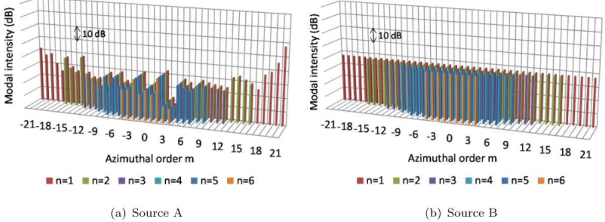
4.4 Measured SPL of each azimuthal mode order at 5 selected fan speeds at 1BPF for fan rig test . . . 46
4.5 An example of a low-frequency ANPRORAD FE mesh for rig intake . . 47
x LIST OF FIGURES
4.6 Source models at subsonic fan-tip speed (50% speed) for the rig geometry 47
4.7 Source models at supersonic fan-tip speed (90% speed) for the rig geometry 49
4.8 Comparison between predicted and measured rig data . . . 50
4.9 Contour plot of SPL of mode (24,1) at 1BPF (90% speed) for the lined configuration . . . 52
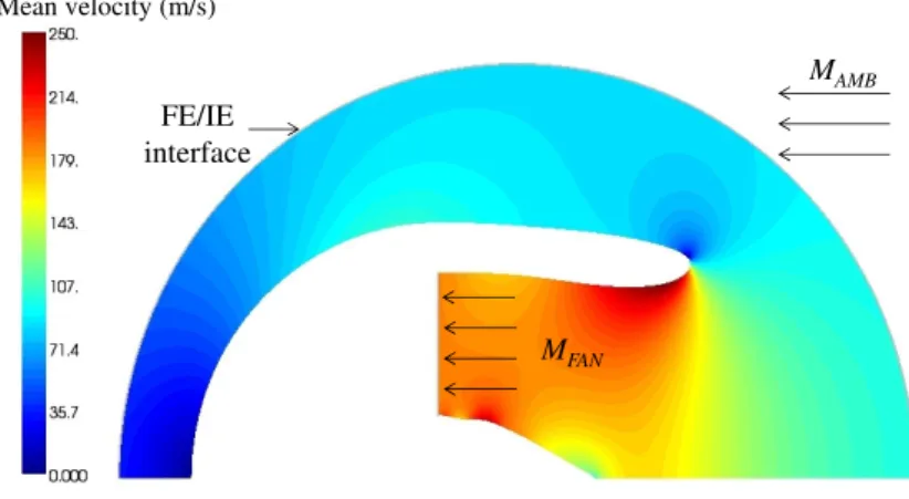
4.10 Contour of mean flow velocity at 90% speed . . . 53
4.11 Field shape of (24,1) mode in the far-field arc at 1BPF (90% speed) for hard-walled and lined configurations; with and without the spinner . . . 54
4.12 Non-linear analysis at 90% speed for rig geometry . . . 55
4.13 Experimental set-up for static noise test for a HBR turbofan engine . . 55
4.14 An example of a low-frequency ANPRORAD FE mesh for engine geometry 56 4.15 Measured SPL of each azimuthal mode order at 5 selected fan speeds at 1BPF for engine test . . . 57
4.16 Source models at subsonic fan-tip speed (70% speed) for the engine geometry . . . 58
4.17 Comparison between predicted and measured engine data . . . 59
5.1 Single layer liner construction of resistanceR and cell depth d . . . 63
5.2 Search space for the SOFT optimisation . . . 67
5.3 Grid showing the points where the CAA evaluations are performed at each iteration in ‘fmincon’ . . . 68
5.4 Intake geometry and liner position . . . 69
5.5 High frequency approximation to predict the far-field SPL directivities for hard walled and lined cases for frequencies greater than 2 kHz at approach condition . . . 70
5.6 SOFT Optimisation of ∆P W L40o→90o at 2kHz at approach condition, characterized by liner resistance R and cell depthd . . . 71
5.7 SOFT optimisation results of ∆P W L40o→90o integrated from 250Hz to 5kHz at approach condition, characterized by liner resistanceR and cell depth d . . . 73
5.8 Results of MATLAB optimisation of intake liner at approach condition. 74 5.9 Overall performance of liners optimised by using SOFT . . . 75
5.10 High frequency approximation to predict the far-field SPL directivities for hard walled and lined cases for some high frequencies at sideline condition . . . 77
5.11 Contours of ∆P W L0o→120o integrated from 250Hz - 5kHz plotted against non-dimensional liner resistanceR and cell depthd at sideline condition 78 5.12 Contours of ∆P W L0o→120o plotted against non-dimensional liner resis-tanceR and cell depthd for MM and SM noise components at 1st BPF at sideline condition . . . 79
5.13 Contours of ∆P W L0o→120o plotted against non-dimensional liner resis-tanceRand cell depthd for MM and SM noise components at 2nd BPF at sideline condition . . . 79
5.14 Contours of ∆P W L0o→120o plotted against non-dimensional liner resis-tanceR and cell depthd for MM and SM noise components at 3rd BPF at sideline condition . . . 80
LIST OF FIGURES xi
5.15 Contours of ∆P W L0o→120o plotted against non-dimensional liner
resis-tance R and cell depth d for the total noise source at the first three BPFs at sideline condition . . . 81
5.16 Far-field SPL directivities for hard-wall and uniformly lined (R=5,d=15mm) configurations at the first three BPFs at sideline condition . . . 82
5.17 Contours of ∆P W L0o→120o plotted against non-dimensional liner
re-sistance R and cell depth d for the entire source spectrum over the considered frequency range . . . 83
5.18 Methodology to apply non-linear adjustments to the linear far-field pre-dictions by ACTRAN/TM by using the results obtained by the analyt-ical non-linear propagation model . . . 84
5.19 Contours of ∆P W L0o→120o plotted against non-dimensional liner
resis-tance R and cell depth d for the entire source spectrum over the con-sidered frequency range including non-linear adjustments to SM tones at BPF . . . 85
5.20 SOFT optimisation results of ∆P W L0o→120o characterized by liner
re-sistance R and cell depth d for the entire source spectrum over the considered frequency range at sideline condition . . . 85
5.21 Far-field SPL directivity of the total noise source at sideline condition; the optimal liner selected by SOFT is used in the lined configuration . . 86
6.1 An unwrapped figure of a uniform cylindrical duct to describe the mod-eling of a hard patch in Cargill code . . . 92
6.2 A uniform cylindrical intake with a uniform zero-spliced lining used for Cargill predictions . . . 93
6.3 Modal PWL (relative to the in incident) along the duct axis with and without a hard patch at the liner start at frequency ka = 27.0. . . 94
6.4 Modal PWL along the duct axis at different frequencies for a hard patch of width 8.9% of the duct circumference located at the start of the liner 95
6.5 Modal PWL along the duct axis for different patch sizes at the liner start location atka=27.0 . . . 97
6.6 Modal PWL at the duct exit atka=27.0 for different patch sizes at the start of the liner . . . 98
6.7 Modal PWL along the duct axis for different patch locations relative to the liner for a patch width 3.8% of the duct circumference at ka=27.0 . 99
6.8 Modal PWL along the duct axis for a patch width of 3.8% of the duct circumference at liner start at ka=27.0 for different SPLs of the rotor-locked incident mode (24,1) at the duct wall close to the fan. . . 101
6.9 Relative sound power level (PWL) predicted by the Cargill model at the duct exit plotted against patch width. . . 102
7.1 Intake models . . . 106
7.2 Liner configurations used in the study . . . 107
7.3 3D meshes used for ACTRAN calculations (mesh resolution: 4 quadratic elements per wavelength) . . . 108
7.4 Axi-symmetric mesh to simulate the uniformly lined case . . . 108
7.5 SPL on the duct wall along the duct axis for the uniformly lined case. . 108
7.6 Contour plot of SPL on the surface of the duct for the uniformly lined case . . . 109
xii LIST OF FIGURES
7.7 Contour plot of SPL along thex −y plane for the uniformly lined case obtained by using the unstructured mesh , extruded mesh and the axi-symmetric mesh . . . 109
7.8 Modal intensity (in dB) at the duct exit . . . 110
7.9 SPL on the duct wall along the duct axis; hard patch located at 90o azimuthal location at the start of the acoustic liner . . . 111
7.10 Modal intensity (in dB) at the exit plane for a lined intake with a hard patch. . . 111
7.11 Contour plot of SPL on the duct surface and on the exit plane for a lined configuration with a square hard patch of different sizes located at the start of the liner . . . 112
7.12 Relative PWL (in dB) at the duct exit for a lined intake with a hard patch located at the start of the liner. . . 113
7.13 Contour plot of SPL on the duct surface and on the exit plane for different locations of a square hard patch of width 3.8% of the duct circumference . . . 114
7.14 PWL at the duct exit for different locations of a hard patch of width 3.8% of the duct circumference . . . 114
7.15 Methodology to apply non-linear adjustments to the linear prediction by ACTRAN/TM for intake model 1 by using the results obtained by the analytical non-linear propagation model . . . 115
7.16 Non-linear adjustments applied to the results obtained by ACTRAN/TM to investigate the patch effect . . . 116
7.17 Intake model 2 with a cross-sectional view of the mean flow profile inside the duct . . . 117
7.18 Unstructured FE mesh over the intake model and ACTRAN/TM results for different mesh resolutions . . . 117
7.19 Contour plot of SPL on the duct surface and on the exit plane for a lined configuration with a hard patch of different sizes, located at the start of the liner . . . 118
7.20 Relative PWL (in dB) at duct exit for a lined intake with a hard patch located at the start of the liner . . . 119
7.21 Effect of patch location on noise attenuation. . . 120
7.22 Non-linear adjustments applied to the results obtained by ACTRAN/TM to investigate the patch effect in intake model 2 . . . 120
7.23 Methodology to predict far-field SPL directivity for a lined intake with a hard patch . . . 122
7.24 Unstructured FE mesh . . . 123
7.25 Mean flow profile in the FE domain . . . 123
7.26 Effect of the hard patch of width 8.9% of the duct circumference in intake model 2 on the attenuation of the MM component . . . 124
7.27 Predicted far-field SPL directivity of the rotor-locked mode (24,1) and the multimode (MM) component . . . 125
7.28 Effect of the hard patch of width 1.6% of the duct circumference on far-field directivity for different protrusions of the mode (24,1) above the MM component . . . 125
7.29 Effect of patch width (in terms of % of the duct circumference) on the far-field directivity for 30dB protrusion of mode (24,1) . . . 126
LIST OF FIGURES xiii
7.30 Methodology of applying non-linear adjustments to the far-field predic-tion by ACTRAN/TM by using the results obtained by the analytical
non-linear propagation model . . . 127
7.31 Non-linear adjustments applied to the far-field results obtained by AC-TRAN/TM at different source levels of rotor-locked mode (24,1) . . . . 127
8.1 Fan flutter caused from the interaction of reflected modes with the fan blades in a turbofan intake . . . 130
8.2 Unsteady pressure patterns generated by 2ND and 2ND vibration modes of the fan . . . 131
8.3 Intake geometry and liner impedances for modes 2ND (2,1) and 3ND (3,1) used for spliced liner configuration . . . 132
8.4 ANPRORAD 3D mesh over the nacelle; hard-wall (left), fully lined (mid-dle) and spliced liner (right) . . . 132
8.5 Relative amplitude of the reflected modes for a hard-walled, fully-lined and spliced intake (splice width represented in terms of % of the duct circumference at the fan plane) . . . 133
8.6 Relative phase of the reflected modes for a hard-walled, fully-lined and spliced intake (splice width represented in terms of % of the duct cir-cumference at the fan plane) . . . 134
8.7 Intake geometry and liner impedance used for segmented liner configu-ration . . . 135
8.8 Relative amplitude of the reflected modes for a hard-walled, uniformly lined and segmented liner configurations 1 and 2 . . . 136
8.9 Relative phase of the reflected modes for a hard-walled, uniformly lined and segmented liner configurations 1 and 2 . . . 136
8.10 Intake geometry and liner impedance used for segmented liner configu-rations with second segment having variable circumferential extent . . . 137
8.11 ANPRORAD 3D mesh over the nacelle; 2nd segment - 0olined (top left), 180o lined (top right), 285o lined (bottom left) and 360o lined (bottom right) . . . 138
8.12 Relative amplitude of the reflected modes for configuration A . . . 138
8.13 Relative phase of the reflected modes for configuration A . . . 139
8.14 Relative amplitude of the reflected modes for configuration B . . . 139
8.15 Relative phase of the reflected modes for configuration B. . . 140
8.16 Reflected modal amplitude relative to incident modal amplitude in hard-walled and uniformly lined intake . . . 140
8.17 SOFT optimisation results of the relative amplitude of the reflected mode (2,1) at engine speeds close to the mode cut-on/cut-off transition. SOFT search points are superimposed on the independently computed contours of reflected modal amplitude against liner resistance and reac-tance . . . 141
8.18 SOFT optimisation results of the relative amplitude of the reflected mode (3,1) at engine speeds close to the mode cut-on/cut-off transition. SOFT search points are superimposed on the independently computed contours of reflected modal amplitude against liner resistance and reac-tance . . . 142
xiv LIST OF FIGURES
8.19 Contour plots of reflected modal amplitude of mode (2,1) against liner resistance and reactance at engine speeds close to the mode cut-on tran-sition. . . 143
8.20 Contour plots of reflected modal amplitude of mode (3,1) against liner resistance and reactance at engine speeds close to the mode cut-on tran-sition. . . 143
8.21 Predicted impedance of selected liners against frequency . . . 144
8.22 Reflected modal amplitudes predicted for segmented liner configurations with selected liners (25%) and community noise liner (75%) . . . 145
A.1 Intake geometry; acoustic liner indicated in red . . . 154
A.2 Hard-wall spectra at different engine conditions . . . 156
B.1 The effect of IE order on the far-field SPL directivity of the BPF modes at sideline condition . . . 158
B.2 Absolute value of acoustic pressure of mode (24,1) at 1BPF (1300Hz) in the FE domain . . . 159
B.3 Absolute value of acoustic pressure of mode (120,1) at 5BPF (6500Hz) in the FE domain . . . 159
B.4 Location of the IE centre with respect to the centre of the FE domain of radius a . . . 159
C.1 An acoustic source enclosed inside a spherical surface. . . 161
List of Tables
4.1 The BPF and the fan-plane axial Mach number of the mean flow at different fan rig speeds . . . 49
5.1 Optimisation results at 2kHz at approach condition. . . 71
5.2 Optimisation results of cost function (∆P W L40o→90o) integrated over
the frequency range of 250Hz to 5kHz at approach condition. . . 73
5.3 Comparison between the optimisation results of SOFT and MATLAB at 2kHz frequency at approach condition. . . 74
5.4 Comparison between the optimisation results of SOFT and MATLAB for a frequency range of 250Hz to 5kHz at approach condition . . . 74
5.5 Methods to combine the individual noise sources over the entire fre-quency range at sideline condition . . . 83
5.6 Results of SOFT optimisation of the intake liner for the total source spectrum over the considered frequency range at sideline condition . . . 86
6.1 Conditions used in the hard patch study . . . 93
8.1 Segmented liner configurations used for flutter analysis . . . 135
8.2 Segmented liner configurations with second segment having variable cir-cumferential extent . . . 137
8.3 SOFT optimisation results at engine speeds near the cut-on/cut-off tran-sition of reflected modes (2,1) and (3,1) . . . 142
A.1 Specifications at the engine conditions . . . 155
A.2 Power levels of MM and SM sources at the first 7 BPF harmonics at different engine conditions . . . 156
B.1 Investigation of NDOF, total time consumed and memory required for ACTRAN/TM computation at 1BPF (1300Hz) for different IE orders . 158
B.2 Investigation of NDOF, total time consumed and memory required for ACTRAN/TM computation at 5BPF (6500Hz) for different IE orders . 158
DECLARATION OF AUTHORSHIP
I, PRATEEK MUSTAFI, declare that this thesis titled,
IMPROVED TURBOFAN INTAKE LINER DESIGN AND OPTIMIZATION
and the work presented in the thesis are both my own, and have been generated by me as the result of my own original research. I confirm that:
• this work was done wholly or mainly while in candidature for a research degree
at this University;
• where any part of this thesis has previously been submitted for a degree or any
other qualification at this University or any other institution, this has been clearly stated;
• where I have consulted the published work of others, this is always clearly
at-tributed;
• where I have quoted from the work of others, the source is always given. With
the exception of such quotations, this thesis is entirely my own work;
• I have acknowledged all main sources of help;
• where the thesis is based on work done by myself jointly with others, I have made
clear exactly what was done by others and what I have contributed myself;
• parts of this work have been published as:
P. Mustafi, R. J. Astley, R. Sugimoto “A computational study of the effects of liner damage on zero-splice turbofan intake liners”, 18th AIAA/CEAS Aeroacoustics Con-ference, Colorado Springs, USA, 4-6 June 2012, AIAA-2012-2152.
P. Mustafi, R. J. Astley, R. Sugimoto and A. J. Kempton “Validation of CAA predic-tions for forward-arc fan noise, and intake liner optimisation”, 15th CEAS-ASC Work-shop on Acoustic Liners and Associated Propagation Techniques, Lausanne, Switzer-land, 13-14 October 2011.
R. J. Astley, R. Sugimoto and P. Mustafi “The effect of hard patches on zero-splice turbofan intake liners, computational study”, Inter-noise, Osaka, Japan, 4-7 September 2011, Paper 450164.
xviii DECLARATION OF AUTHORSHIP R. J. Astley, R. Sugimoto and P. Mustafi “Computational aero-acoustics for fan duct propagation and radiation. Current status and application to turbofan liner optimisa-tion”, Journal of Sound and Vibration, Vol. 330, Issue 16, 3832-3845.
R. J. Astley, R. Sugimoto, P. Mustafi, M. F. Kewin and I. M. Achunche “Applying Computational Aero-Acoustics (CAA) to turbofan liner optimisation”, 20th Interna-tional Congress on Acoustics, Sydney, Australia, 23-27 August 2010, Paper 354.
R. J. Astley, R. Sugimoto and P. Mustafi “The application of computational Aero-acoustics (CAA) to automated liner optimisation of turbofan ducts”, 17th International Congress on Sound and Vibration (ICSV), Cairo, Egypt, 18-22 July 2010, Paper 817.
R. J. Astley, R. Sugimoto, P. Mustafi, M. F. Kewin and I. M. Achunche “Liner opti-misation for turbofan ducts - towards a fully automated procedure”, 16th AIAA/CEAS Aeroacoustics Conference, Stockholm, Sweden, 7-9 June 2010, AIAA-2010-3826.
R. J. Astley, R. Sugimoto, I. M. Achunche, M. F. Kewin, P. Mustafi and E. P. Deane “A review of CAA for fan duct propagation and radiation, with application to liner optimisation”, Procedia Engineering, IUTAM Symposium on Computational Aero-Acoustics for Aircraft Noise Prediction, Southampton, UK, 29-31 March 2010, Vol. 6, 143-152.
Signed:
Acknowledgements
Firstly, I would gratefully acknowledge the financial support for my PhD study pro-vided jointly by Engineering and Physical Sciences Research Council (EPSRC) and by Rolls-Royce plc through a Dorothy Hodgkin postgraduate Award (DHPA). I am thankful to the Rolls-Royce University Technology Centre in Gas Turbine Noise at ISVR to provide me an opportunity to contribute to an industrially focussed research, something which I always wanted to do.
I am very grateful to my academic supervisors, Prof. Jeremy Astley and Dr. Rie Sugi-moto, for their advice and immense support in my research. Under their guidance and attention to details, I gained invaluable experience both academically and personally. I would also like to thank my industrial supervisor Dr Andrew Kempton (Rolls-Royce UK) for providing me an opportunity to work on many industrial projects and to increase my learning curve in the field of aero-acoustics.
The research was greatly benefitted from useful interactions with many individuals. In particular, I would like to thank: Steeve Laldjee (FFT) for the development of PHOENIX and for his support with ACTRAN/TM; Brian Tester (ISVR) for his advise on using the Cargill code; Dr. Alan McAlpine (ISVR) for his advice on non-linear propagation theory; Christoph Richter (Rolls-Royce Deutschland) for providing the data on liner damage study and Iansteel Achunche (Rolls-Royce UK) for his advice on using SOFT.
During the course of three years, I had an opportunity to meet many friendly people. Here are a few to list: Iansteel Achunche, Feargus Kewin, Eugene Deane, Vincent Blandeau, Samuel Sinayoko, Martina Dieste, Mattieu Gruber, Adriana Salgado, Mahdi Azarpeyvand, Jack Lawrence, Albert Prinn, Hessam Alavi, Prathiban Sureshkumar, Zbigniew Rarata, Paul Rodga, Luis Tafur, Jon Stone, Upol Islam and the list goes on...
Last but not the least, I would like to thank my mom, my dad and my sister for for their priceless love and support during my PhD study. Even though they were conti-nents apart, I felt that they were always with me here in Southampton.
Prateek Mustafi, February 12, 2013.
Abbreviations
ACARE Advisory Council for Aeronautics Research
ANPRORAD ANalysis for PROpagation and RADiation
ARMOGA Adaptive Range Multi-Objective Genetic Algorithm
BB Broadband noise source
BEM Boundary Element Method
BPF Blade Passing Frequency
BR Bypass Ratio
B-induct Bypass induct analysis
CAA Computational Aero-Acoustics
CFD Computational Fluid Dynamics
DDOF Double Degree Of Freedom
DoF Design of Experiments
DGM Discontinuous Galerkin Method
DHC Dynamic Hill Climbing
DNS Direct numerical simulation
DoE Design of Experiment
EIPM Equal Intensity Per Mode source
EO Engine Order
EPNL Effective Perceived Noise Level
FDNS Frequency Domain Numerical Simulation
FE Finite Element
FEM Finite Element Method
FFT Free Field Technologies
GA Genetic Algorithm
GUI Graphical User Interphase
HBR High Bypass Ratio
HW Hard-Walled
ICAO International Civil Aviation Organization
IE Infinite Element
IHI Ishikawajima-Harima Heavy Industries
IL Intensity Level
ISVR Institute of Sound and Vibration Research xxi
xxii ABBREVIATIONS
LEE Linearised Euler Equation(s)
MM Multi-Mode noise source model
ND Nodal Diameter
NL Non-Linear
OFS Outer Fixed Structure
OGV Outlet Guide Vane
Optimtool Optimisation Toolbox
PHOENIX Parametric mesHing and analysis of aerOENgine Intakes and eXhausts
PNL Perceived Noise Level
POA Percentage Open Area (porosity)
PWL PoWer Level
RBF Radial Basis Function
RSM Response Surface Modelling
SDOF Single Degree Of Freedom
SM Single-Mode noise source model
SOFT Smart Optimisation For Turbomachinery
SPL Sound Pressure Level
Symbols
(r, θ, ψ) Spherical coordinate system
(r, θ, z) Cylindrical coordinate system
(x, y, z) Cartesian coordinate system
(x, y, z) Cartesian coordinate system
(ˆi,ˆj,ˆk) Cartesian unit vector notations ˆ
n unit vector perpendicular to a surface
S denotes surface
V denotes volume
error
CP specific heat capacity at constant pressure CV specific heat capacity at constant volume
γ ratio of specific heats (CP/CV) ω angular frequency
ωmnco modal cut-off frequency
t time
i √−1
f frequency
λ wavelength
c speed of sound; no subscript: acoustic component,no subscript: 0 mean
flow component,T total k acoustic wavenumber
M Mach number; subscript: t fan-tip Mach number, a fan-plane axial Mach
number,rel relative Mach number at the fan (=
p
M2
a +Mt2) m azimuthal mode order
n radial mode order
a radius of a cylindrical duct or fan radius of a turbofan intake
D duct diameter or fan diameter
B number of fan blades
I acoustic intensity
W, w FE weighting function or test function
C damping term
F forcing term
xxiv SYMBOLS
K acoustic stiffness term
M acoustic mass term
Z, z specific acoustic impedance of the acoustic liner
R specific liner resistance
X, χ specific liner reactance
l liner mass inertance
d liner cell depth
β coefficient of nonlinearity (= γ+12 )
σ linear attenuation rate of an acoustic wave
ρ density;no subscript orsuperscript: ∗ acoustic component,subscript:
0 mean flow component
p pressure; no subscript orsuperscript: ∗ acoustic component,subscript:
0 mean flow component, s shock strength of a non-linear wave
u particle velocity;no subscript orsuperscript: ∗ acoustic component, subscript: 0 mean flow component
φ velocity potential;superscript: ∗ acoustic component,subscript: 0 mean
flow component, i at element node
Amn, Bmn modal wave amplitude; superscript: + wave travelling in positive
z-direction, - wave travelling in negetivez-direction
Nmn modal nomalisation factor kmnco modal cut-off wavenumber
kz, kz,mn axial wavenumber;superscript: + wave travelling in positivez-direction,
- wave travelling in negetivez-direction
kr,mn radial wavenumber
Chapter 1
Introduction
1.1
Background
Over the last decade, the commercial air traffic has increased significantly across the globe (ICAO) [1]. This has posed serious concerns about the impact of the increasing aircraft noise on the people residing close to the airports. As a result, stringent regula-tions on noise restricregula-tions have been implemented by government organisaregula-tions [1–3]. Such noise legislations encourage research which aim at the reduction of aircraft noise. A target of a 10dB reduction in the total aircraft noise to be achieved in 2020 start-ing from a datum level in 2000 (see figure1.1) has been set by the Advisory Council of Aeronautics Research in Europe (ACARE) [4]. The reduction of aircraft noise is therefore a vital factor in the development of new aircrafts. This requires that the different sources of aircraft noise to be identified and novel noise reduction techniques to be developed in order to target these noise sources.
Figure 1.1: Time history of noise reduction in aero-engines [3]
2 Chapter 1 Introduction
1.2
Aircraft noise sources
Total aircraft noise can be broadly subdivided into two categories - airframe noise and engine noise [5–7](figure1.2). Airframe noise is generated by unsteady flow interacting with the airframe itself (high lift devices, landing gears, etc.). Engine noise constitutes a wide variety of noise sources for which the frequency spectra vary drastically at dif-ferent shaft rotational speeds of the engine. These sources include noise from the jet, fan, compressor, combustor and turbine.
Leading edge devices Tail plane Wing Tailing edge devices Spoiler Fuselage Landing gears Nacelle
Fan exhaust Turbine & Core
Fan intake Jet
Figure 1.2: Aircraft noise sources [8]
In early jet engines, much of the audible noise was generated by the hot exhaust gases mixing with the surrounding air at the rear of the engine [3, 7]. By introducing a fan at the front of the engine, most of the thrust is produced by the air bypassed around the core. This allowed a lower jet core velocity in turn reducing jet noise. The noise emitted by modern commercial aircrafts is substantially less than that produced by designs fifty years ago (figure 1.3). However, the introduction of a large fan in modern turbofan engines has led to fan noise overtaking the jet as the dominant noise source. Unlike jet noise, the fan noise is radiated both forward of the engine through the intake (or inlet) and rearward through the bypass duct as shown in figure1.4. Fan noise can be subdivided into broadband (continuous frequency range) and tonal (at discrete frequencies) noise.
Broadband noise is generated when a turbulent flow interacts with stationary or moving solid surfaces, primarily the leading and trailing edges of the rotor and Outlet Guide Vanes (OGVs). In order to model this noise source in terms of duct acoustic modes, it is generally represented as an ensemble of all the uncorrelated cut-on modes at the fan plane [10–14].
Tonal noise can be classified as tones produced at the harmonics of the Blade Passing Frequency (BPF) and the Engine Order (EO) tones. BPF tones can be generated by the rotating pressure field on the fan plane locked to the rotor (rotor-locked tones) or
Chapter 1 Introduction 3 Compressor Turbine & Combustion Jet Compressor Fan Turbine & Combustion Jet
(a) Typical 1960s design Compressor Turbine & Combustion Jet Compressor Fan Turbine & Combustion Jet
(b) Typical modern design
Figure 1.3: Magnitude and directivity of the radiated sound power of different
engine noise sources for a typical 1960s and a modern design [7]
Forward-arc fan noise Rear-arc fan noise
Core noise
Fan Compressor
Combustor
Turbine Bypass mixing Core mixing Acoustic liner
Figure 1.4: Fan noise radiation through intake and bypass sections of a modern turbofan engine [9]
by the periodic interactions of the rotor wakes with the OGVs (rotor-stator interac-tion tones) or by flow distorinterac-tion effects (distorinterac-tion tones) [7]. Rotor-locked tones are generated only at high fan operating conditions when the fan-tip speed is supersonic. In terms of duct acoustic modes, the rotor-locked tones are modelled as modes with azimuthal orders which are integer multiples of the number of fan blades. Engine order or “Buzz-saw” tones occur in the intake at ‘engine orders’ (integer multiples of shaft rotational frequency). They exist only when the fan-tip speed is supersonic and are generated due to small variations in fan blade stagger angles. [15].
A key method to control fan noise is the use of acoustic treatment in the intake and by-pass sections of the engine (figure1.4). They are typically formed from single or double layers of honeycomb material, separated from the mean flow by a porous facing sheet,
4 Chapter 1 Introduction
Facing and septum sheets
Rigid backing sheets Flow
Figure 1.5: Single layer and double layer liner constructions [16]
and fixed to a rigid backing plate (figure1.5). The design of this acoustic treatment de-pends on the desired Effective Perceived Noise Level (EPNL) [6] to be achieved. EPNL is an ISO standard for measuring aircraft noise that takes into account the frequency, noise content and duration of the event. There are three noise certification points set by ICAO to calculate EPNL. Two of which are at take-off (sideline and cutback) and one during landing (approach) [3, 7]. The engine is at the maximum power setting during sideline engine condition. Cut-back condition refers to a reduced power setting after the initial climb. The engine is at a low power setting during landing and is said to operate at the approach condition. This means that the acoustic treatment must have the appropriate attenuation characteristics at these certification conditions, within the limit of its specified length and weight.
1.3
Aims, motivation and original contributions
The research presented in this thesis has been performed in close collaboration with Rolls-Royce plc. The objective of the research is to provide an improved turbofan liner design capable of reducing community noise and low-frequency reflections at the fan which trigger fan blade instabilities. The research also aims at investigating the effects of liner damage and repair on the performance of zero-splice liners to establish some preliminary guidelines for liner damage/repair limit. The scope of this research is limited only to the intake section of a turbofan engine.
Computational Aero-Acoustic (CAA) methods are well developed for predicting prop-agation of sound on subsonic flows [9] and using such methods in place of measured data is highly beneficial since the acquisition of the latter is costly and time consuming. In order to use a CAA method confidently for predicting turbofan noise, a thorough assessment and validation of the method is required. In this thesis, a commercial
Chapter 1 Introduction 5
Finite/Infinite Element (FE/IE) code ACTRAN/TM is used to predict noise propa-gation in turbofan intakes and radiation into the far-field. The code is also validated against the measured data. The capabilities of ACTRAN/TM have been exploited extensively both for predicting far-field radiated noise and acoustic reflections at low frequencies.
ACTRAN/TM is however based on a linear theory and cannot model the propagation of high amplitude tones which are strongly excited at supersonic fan-tip speeds. An analytical model devised by Morfey and Fisher [17] and Fisher et al. [18] and later extended by McAlpine et al. [15, 19] is used to predict the propagation of tones at such speeds.
The original contributions of this thesis are listed below:
I. A methodology is developed to apply non-linear adjustments by using ‘Morfey-Fisher model’ to the results obtained by linear prediction models to correctly determine the attenuation of tones at supersonic fan-tip speeds.
II. Far-field noise predictions are validated against turbofan rig and engine test data by using complex noise source models directly derived from hard-walled in-duct and far-field measurements, in addition to the conventional ‘equal-energy’ source models.
III. ACTRAN/TM shell codes like ANPRORAD and PHOENIX (detailed in chap-ter2) are used within automated optimisation routines to perform liner optimi-sation to reduce far-field radiated noise. The optimioptimi-sation study is performed for realistic geometries and noise source models at two different engine conditions including non-linear corrections to the attenuation of BPF tones.
IV. The effects of size and location of linear damage on the noise attenuation by zero-splice intake liners are investigated at different fan speeds by an existing analytical asymptotic model. The results are compared to ACTRAN/TM. The study is extended for realistic intake geometries with non-uniform flow profiles by using ACTRAN/TM with the aim to predict the effects of liner patches on far-field noise directivities. The study provides some essential guidelines for the size and the location of liner damage/repair limit.
V. The acoustic impact of different liner configurations on the amplitude of low-frequency acoustic reflections from low order incident modes are assessed by using ACTRAN/TM (both axisymmetric and 3D intake models).
6 Chapter 1 Introduction
1.4
Report overview
The research work presented in this thesis is broad in context focussing on varied topics which are closely related. They range from the development of a fully automated pro-cedure to optimise intake liners to reduce community noise and low-frequency acoustic reflections, to the investigation of the effects of liner damage to the noise reducing capabilities of a zero-splice liner. Since this thesis covers a wide range of topics, the literature review for each topic is presented separately.
This thesis consists of 9 chapters. Chapter 2 describes the CAA tool ACTRAN/TM used to predict fan noise propagation and radiation from turbofan intakes. This is followed by a description of the non-linear propagation model in chapter 3.
In chapter4, The far-field Sound Pressure Level (SPL) predictions are validated against measured data for the available source information and liner details. In chapter 5, ACTRAN/TM is embedded within optimisation routines to develop fully-automated optimization schemes to optimize intake liners to reduce far-field radiated noise at approach and sideline engine conditions. Non-linear adjustments are applied to high-amplitude tones at sideline condition.
In chapter6, an analytical asymptotic model is used as a benchmark to investigate the acoustic effects of liner damage and repair on the performance of a zero-splice intake liner. The study performed in this chapter is a precursor to comprehensive CAA modelling in chapter 7. In chapter 7, ACTRAN/TM is used to predict the effects of liner damage on noise attenuation in a realistic intake geometry and non-uniform mean flow. A number of models with different degree of simplification of the intake geometry are used to investigate the influence of such simplifications on the results.
In chapter 8, different liner configurations are analyzed for reducing low frequency acoustic reflections at the fan. The liner is also optimised to minimize these reflection by using the automated optimisation routine used in chapter 5.
Finally in chapter 9, overall conclusions and recommendations for future work are presented.
1.5
Planning and progress
An overview of the work plan is shown in figure 1.6 indicating the tasks which were undertaken in the course of three years.
Chapter 1 Introduction 7
O N D J F M A M J J A S O N D J F M A M J J A S O N D J F M A M J J A S
Optimisation of single layer liners for broadband noise at approach condition Assessment of relative merits of different optimisation suites Automatic optimisation of
intake liners to reduce forward-arc fan noise M.Sc. taught courses Generic skills training
Courses YEAR 2 (2010-2011) Q1 Q2 Q3 Q4 Q1 Q4 TASKS YEAR 1 (2009-2010) Q2 Q3 YEAR 3 (2011-2012) Q1 Q2 Q3 Q4 Formulation of high frequency approximation for all sources
Assessment of liner damage on zero-splice
intake liners Parametric study using an analytical asymptotic code (Cargillv13)
Understanding the theory of non-linear acoustics Liner optimisation for all source types (single mode and multi-mode) at sideline condition
Liner optimisation at sideline condition including non-linear adjuatments applied to tones
Implementation of non-linear adjustments to Cargill code
Validating Cargill results with ACTRAN/TM Assessment of the applicability of different predictions models using ACTRAN/TM, with the implementation of non-linear adjustments
Acoustic analysis of liners for fan-flutter Flutter analysis for spliced liner configuration
Engine predictions Reporting, attending seminars, workshops and
conferences Flutter analysis for segmented liner
Flutter analysis for virtually scarfed liners
Automatic optimisation of liners for fan-flutter
Validation of ACTRAN/TM based
far-field predictions with measurements at BPF for
different fan speeds Rig predictions
Chapter 2
Linear prediction method for fan
noise propagation and radiation
2.1
Introduction
Accurate estimates of Effective Perceived Noise Level (EPNL) for commercial aircraft are required for noise certification and for assessing compliance with local community noise regulations. Noise data from rig and engine tests provide the most reliable ba-sis for such predictions. However, such data are costly to acquire and cannot always be extrapolated in a straightforward way to new configurations. Accurate predic-tion schemes to predict noise propagapredic-tion and radiapredic-tion from the engine are therefore crucial in the preliminary engine design stage. This chapter describes the prediction method based on linear propagation theory, which is used in this thesis to model the propagation of sound in intake ducts and radiation to the far field.
2.2
Literature Review
Analytic methods to predict sound propagation in turbofan ducts were developed by many authors in the past but were applicable only to uniform cylindrical and annular duct. An overview of some of these methods is given by Eversman [20]. Sound field which can be represented in terms of the duct modes [21] forms the basis for most analytical and semi-analytical methods. They include hard-wall eigenvalue solutions for sound absorption in ducts of regular geometry, mode matching codes and sound radiation models for cylindrical and annular ducts.
Unlike the eigenvalues calculated for a hard-wall duct, determination of eigenvalues for a lined duct is not a straight-forward task due to the complexity involved in solving the transcendental equations [20]. One of the first attempts in this field was presented by
10 Chapter 2 Linear prediction method for fan noise propagation and radiation
Morse and Ingard [22] who dealt with a no-flow problem, producing charts relating the wall impedance to the eigenvalues without actually solving the eigenvalue equation ex-plicitly. Later, Eversman [20] developed an integration scheme to solve the eigenvalue equation in presence of a mean flow. The scheme used a fourth-order Runge-Kutta integration with a variable step size, and a Newton-Raphson routine for refining the solution. Brooks [23] used the same scheme to track the lined eigenvalues for an acous-tically lined rectangular duct by using the hard-wall eigenvalues as the initial values to the integration scheme.
To calculate the acoustic field in ducts with axial discontinuities in liner impedance, McAlpine et al. [24] developed a mode-matching code which involves the matching of acoustic modes in different lined segments of a uniform duct, in terms of acoustic pressure and axial particle velocity. Later, Astley et al.[25] proposed an alternative mode matching formulation in which the matching was based on continuity of mass and axial momentum at the liner discontinuities, as opposed to pressure and velocity matching.
With regards to estimating sound radiation into the far-field from aero-engine ducts, Rice [26, 27] established a relationship between the the peak in far-field directivity patterns and duct mode cut-off ratio. It was shown that a nearly cut-off mode would radiate predominantly at 90o from the duct axis while the well propagating modes radiate nearer to the axis. Gabard and Astley [28] derived an exact solution to predict the sound field radiated from an axisymmetric annular duct with infinite center body including a bypass shear layer. This work was an extension to the study performed by Munt [29] who considered a problem of circular jet with bypass shear layer, and to Rienstra [30] for a semi-infinite duct with an infinite centre body, using Wiener-Hopf technique.
However, the analytical models cannot capture the effects of a realistic geometry and flow. Numerical methods are therefore important to assess the effect of the realistic geometry and mean flow. Over the last decade, Computational Aero-Acoustics (CAA) methods have been developed to study propagation of sound on subsonic flows and have been used extensively by many authors in the past. Methods that are widely used for modelling of sound propagation from turbofan ducts include Boundary Ele-ment (BE) methods [31], Finite and Infinite Element (FE/IE) models [32–34] and other Computational Aero-Acoustics (CAA) methods, based on the solution of the full [35] or Linearised Euler Equations (LEE) [36,37]. The solutions of full Euler equations are important in modelling non-linear propagation effects due to large acoustic perturba-tions. For flows where non-linear effects are less significant, schemes which solve LEEs are generally used. Although LEEs omit the viscous effects, they can deal with sheared or rotational flows if the mean flow is solved by using Reynolds Averaged Navier Stokes (RANS) solvers [36, 37]. This makes them suitable especially for bypass and exhaust flow problems. BE and FE/IE models solve a convected wave equation in the frequency
Chapter 2 Linear prediction method for fan noise propagation and radiation 11
domain and are applicable only when the mean flow is irrotational. A detailed review of some of these computational methods can be found in references [9,38].
The computational tool used in this study for predicting noise propagation in turbofan ducts and radiation into the far-field is the commercial FE/IE code, ACTRAN/TM, de-veloped by Free Field Technologies (FFT), Belgium. This chapter explores the acoustic propagation model used in ACTRAN/TM. The FE formulation and the IE model used in ACTRAN/TM have been outlined. The shell codes, ANPRORAD and PHOENIX, used in this thesis to perform ACTRAN/TM predictions in turbofan intakes are also described.
2.3
Acoustic propagation model
Viscous effects are generally neglected in the modeling of sound propagation from turbofan ducts since such losses are significant only over large propagation distances. Therefore, Euler equations form the starting point for most computational models [9], and in most instances they are simplified by linearising the small amplitude unsteady perturbations on the steady mean flow. The resulting equations are given by
∂ρ∗ ∂t +∇ ·(ρ ∗u 0+ρ0u∗) = 0, (2.1) and ρ0 ∂ ∂t+u0· ∇ u∗+ρ0(u∗· ∇)u0+ρ∗(u0· ∇)u0+∇p∗ =0. (2.2)
Equations2.1and 2.2are the linearized Euler equations for continuity and momentum respectively, whereρ,p andudenote density, pressure and velocity respectively. Mean flow quantities are denoted by the subscript 0, and unsteady perturbations
quanti-ties are denoted by the superscript ∗. For isentropic mean flow, there exist a simple relationship between the unsteady pressure and density perturbations [39–41]:
p∗=c02ρ∗. (2.3) In Equation2.3,c0 is the local speed of sound in the mean flow. The problem reduces
to the solution of equations 2.1 and 2.2 for variables p∗ (or ρ∗) and u∗. Further simplification can be made if the flow is irrotational in the perturbed velocity u∗ can be written in terms of an acoustic velocity potentialφ∗, as u∗ =∇φ∗. The linearized
continuity and momentum equations can then be expressed as [9]
∂ρ∗
∂t +∇ ·(ρ
∗u
12 Chapter 2 Linear prediction method for fan noise propagation and radiation and p∗=c02ρ∗=−ρ0 ∂ ∂t +u0· ∇ φ∗. (2.5)
Time-harmonic versions of these equations are obtained by rewritingφ∗(x,t) asφ(x)eiωt, whereω(= 2πf) is the radian frequency and φis the complex amplitude. Using equa-tions2.4and 2.5, the convected Helmholtz equation can be obtained [39].
(iω+∇ ·u0+u0· ∇) ρ0 c2 0 (iω+u0· ∇)φ − ∇ ·(ρ0∇φ) =0. (2.6)
The problem now reduces to the solution of a single unknown parameter, the acoustic velocity potential φ. To obtain a solution of acoustic field by using equation 2.6, boundary conditions of the surrounding body or surfaces must be defined.
2.3.1 Impedance boundary conditions
The boundary condition on all rigid surfaces is that of zero normal particle velocity giving ∇φ∗·ˆn=0, where ˆn is a unit vector perpendicular to the surface. For a duct lined with a locally reacting liner, the relationship between the acoustic pressure p∗ and normal component of the acoustic particle velocity u∗ at the duct wall in the absence of mean flow [20,41], is given by
u∗·ˆn= p
∗
Z , (2.7)
where, Z is the specific acoustic impedance of the liner. For a hard-walled duct u∗ is zero at the wall and |Z|=∞ (from equation 2.7). In presence of a uniform flow U0,
an infinitely thin boundary layer is assumed to be present at the impedance surface, giving Eversman’s [42] implementation of Myers [43] boundary condition:
u∗·nˆ= p ∗ Z +U0· ∇ p∗ iωZ − p ∗ iωZnˆ·(nˆ· ∇U0). (2.8)
2.3.2 Sound propagation in a uniform duct with uniform mean flow
Consider a uniform cylindrical duct with circular cross section (an idealised form of a turbofan intake duct) of radiusa (figure2.1). In case of a uniform mean flow of Mach number M along the duct axis z, the convected Helmholtz equation (equation 2.6) simplifies to ∇2φ−M2∂ 2φ ∂z2 −2ikM ∂φ ∂z +k 2φ= 0, (2.9)
Chapter 2 Linear prediction method for fan noise propagation and radiation 13
where k(=ω/c0) ia the free-field wavenumber of the acoustic wave. In cylindrical
co-ordinates (r, θ,z), equation2.9 can be written as
y r
x
z θ
a
Figure 2.1: Cylindrical duct of circular cross-section of radiusa
∂2φ ∂r2 + 1 r ∂φ ∂r + 1 r2 ∂2φ ∂θ2 −(1−M 2)∂2φ ∂z2 −2ikM ∂φ ∂z +k 2φ= 0. (2.10)
The general solution of equation 2.10 for the acoustic velocity potential can be ex-pressed in terms of a summation of all the duct modes [12,39].
φmn(r, θ, z) = ∞ X m=−∞ ∞ X n=1 J|m|(kr,mnr)eimθ Bmn+ e−ik+z,mnz+B− mne −ikz,mn− z , (2.11)
where m is the azimuthal mode order, n is the radial mode order, Bmn is the modal
amplitude of the acoustic velocity potential for mode (m,n),J|m|is the Bessel function
of order |m|, kr,mn is the radial wavenumber and kz,mn is the axial wavenumber for mode (m,n). Superscripts ‘+’ and ‘−’ denote the quantities for the modes propagating in the positive and negativez directions respectively. Equivalently, using equation2.5, the solution can be obtained in terms of acoustic pressure
pmn(r, θ, z) = ∞ X m=−∞ ∞ X n=1 J|m|(kr,mnr)eimθ A+mne−ikz,mn+ z+A− mne−ik − z,mnz , (2.12)
where Amn is the modal amplitude of the acoustic pressure for mode (m,n), and is
related toBmn by the relation
14 Chapter 2 Linear prediction method for fan noise propagation and radiation
The axial and the radial numbers are related by the dispersion relationship
k±z,mn=
−kM±qk2−(1−M2)k2
r,mn
(1−M2) . (2.14)
The radial wavenumber kr,mn can be obtained by imposing the impedance boundary condition at the duct wall. In the presence of a uniform axial flow, the equation 2.8
simplifies to ∂φ ∂r =− ρ0c0 Z ikφ+M∂φ ∂z − 1 ik M ∂ ∂z ρ0c0 Z ikφ+M∂φ ∂z . (2.15)
The hard-wall boundary condition at the duct wall is obtained by setting |Z| = ∞, which gives∂φ/∂r= 0 atr=a. Therefore, substituting equation2.11into equation2.15
and setting Z(ω) =∞, gives
J0|m|(kr,mna) = 0, (2.16)
where J0 is the derivative of the bessel function with respect to the radial distance r. Similarly, the boundary condition for an acoustically lined duct of liner impedance Z at the duct wall (r=a), is given by
kr,mnJ 0 |m|(kr,mna) J|m|(kr,mna) = ρ0iω Z 1−M kz,mn k 2 . (2.17)
Equation2.12is a general solution for acoustic pressure within a cylindrical duct with circular cross-section. A similar expression can be obtained for an annular duct with inner and outer radius b and a respectively, which is given by
pmn(r, θ, z) = ∞ X m=−∞ ∞ X n=1 J|m|(kr,mnr) +CY|m|(kr,mnr) eimθ A+mne−ik+z,mnz+A− mne −ik−z,mnz , (2.18)
whereY|m|is the Neumanns function of order |m|and C is given by [39]
C =−J
0
|m|(kr,mna)
Y0|m|(kr,mna) .
Chapter 2 Linear prediction method for fan noise propagation and radiation 15
2.3.2.1 Cut-on frequency
The cut-on frequency in a hard-wall duct is the minimal frequency at which a given acoustic mode (m,n) starts to propagate. From the dispersion relationship (equa-tion2.14), one can see that if the value ofk2−(1−M2)k2
r,mn is positive, then the axial
wavenumberkz,mn is entirely real, in which case the mode is ‘cut-on’ and it propagates
along the duct. But, if the value of k2−(1−M2)k2r,mn is negative, then the axial wavenumber kx,mn is has an imaginary part, in which case the mode is ‘cut-off’ and
it represents decaying or evanescent waves. Therefore, for a given mode (m,n), the cut-on wavenumber is given by [39]
kmnco =kr,mn
p
1−M2. (2.19)
However, for a lined duct mode, the term ‘cut-on’ has no meaning as all the modes decay as they propagate along the duct. All the modes decay at different rates which depends on the magnitude of the imaginary part of the axial wave number (Im(kz,mn))
2.4
CAA prediction tool - ACTRAN/TM
The CAA tool used in this thesis is a frequency domain, commercial FE/IE code AC-TRAN/TM [39]. It is based on the convected Helmholtz formulation for the acoustic velocity potential (equation 2.6). Within this application, the acoustic source at the source plane is defined in terms of a modal boundary condition where the incident acoustic field is defined in terms of rigid-wall duct modes (equation 2.12 for circu-lar ducts and equation 2.18 for annular ducts). The reflected modes at this modal boundary are obtained as part of the solution. The impedance boundary condition (equation2.8) is applied in terms of liner admittance for acoustically lined duct walls. ACTRAN analysis can be performed for both two-dimensional (2D) or axisymmetric geometries and three dimensional (3D) non-axisymmetrical geometries.
For radiation problems, ACTRAN/TM uses an FE/IE model of the type proposed by Astley [32,33]. The model is based on a partitioned approach in which the inner acoustic domain is modelled by Finite Elements and the outer acoustic domain which extends to infinity, is modelled using a layer of Infinite Elements (IE).
2.4.1 The FE formulation
The FE method is based on variational formulation which seeks to obtain an approx-imate solution of the convected wave equation such that the weighted average of the error is zero. This is known as the weighted residual technique [44] and is applied to
16 Chapter 2 Linear prediction method for fan noise propagation and radiation
the continuity equation (equation 2.4). Considering time-harmonic dependence of the acoustic variables, equation2.4and can be written as
iωρ+∇ ·(ρu0+ρ0∇φ) = 0. (2.20)
Ifρa and φa are considered to be approximate solutions of equation2.20, then
iωρa+∇ ·(ρau0+ρ0∇φa) =6= 0, (2.21)
where is the error or residual. The approximate solutions ρa and φa are sought
by ensuring that the average of the weighted residual is zero over the computational domain of volumeV, which gives
Z
V
W(iωρa+∇ ·(ρau0+ρ0∇φa))dV = 0,∀W, (2.22)
where W is the weighting or test function. By using the divergence theorem, equa-tion 2.22can be rearranged to give
Z V (∇W ·(ρau0+ρ0∇φa)−W iωρ)dV = Z S W ·(ρau0+ρ0∇φa)·ndS, (2.23)
where S is the bounding surface of the computational domain and n is a unit vector normal to the surface pointing into the domain. Equation2.23is required to hold true for all possible weighting functionW.
Substituting the approximate solutions ρa and φa into equation 2.5 and considering
time-harmonic dependence, it gives
ρa=−
ρ0
c20 (iω+u0· ∇)φa. (2.24)
Substituting equation2.24into equation2.23results in the variational formulation for the convected wave equation:
Chapter 2 Linear prediction method for fan noise propagation and radiation 17 Z V ρ0 c20 c 2 0∇W · ∇φa−(u0· ∇φa) (u0· ∇W) dV + Z V ρ0 c2 0 iωφa(W(u0· ∇φa)−(u0· ∇W))−ω2W φa dV = Z S ρ0 c20 c 2 0W∇φa−u0W(u0· ∇φa)−iωu0Wφa ·ndS. (2.25)
For a hard wall boundary, both u0·n and φa·n are equal to zero. The right hand
side of equation2.25is then zero. For a lined wall however, only u0·nis zero and the
Myers boundary condition is implemented forφa·n. At the source and exit planes of
the duct,φa·n is prescribed in terms of duct modes.
In the FE formulation, the entire computational domain is discretised into a number of sub-volumes called finite elements. Nodes are defined at the element vertices. For quadratic elements, nodes are also located at the mid-point of the element sides. The approximate solutionφais calculated at each node. Equation2.25now transforms into a summation of the volume and surface integrals for each element in the entire domain. The velocity potentialφawithin the entire computational domain can be expressed as
φa=
N
X
i=1
Niφi, (2.26)
whereN is the total number of nodes. Ni is the element shape function associated with
nodei, which is defined by the topology of the associated element [39]. φi is the value
of the velocity potential corresponding to nodei, which is an unknown quantity. The weighting function associated with each node is chosen to be equal to shape function
Wi =Ni. (2.27)
Substituting equations2.26and2.28into equation2.25results in a matrix equation of the form
K+iωC−ω2MΦ =F, (2.28)
where Φ is a vector which contains the unknown values of velocity potential at each nodal point in the computational domain. K,C, Mand Fare the stiffness, damping and mass matrices and forcing vector respectively. These are determined solely by the shape functions and boundary conditions prescribed at the surfaces of the domain. Equation2.28is solved in ACTRAN/TM and nodal values of acoustic velocity potential are obtained.
18 Chapter 2 Linear prediction method for fan noise propagation and radiation
2.4.2 Infinite elements
When modelling free-field radiation problems, the entire unbounded acoustic domain may not be discretised by using FE mesh for obvious reasons. Infinite element scheme [45–
47] is used in ACTRAN/TM to deal with such problems. In this scheme, the exterior domain in not truncated but is represented by using elements of infinite extent. The sound field within infinite elements is represented as outwardly propagating wave-like solutions such that the wave field satisfies Sommerfeld radiation condition in the far-field. This condition requires that
r ∂p ∂r +ikp →0 as r→ ∞ (2.29)
where r is the radial distance from the source. A wave field satisfying equation 2.29
can be represented as an infinite series of ‘multipole’ terms of the form
p(r, θ, φ, k) =e−ikr ∞ X ν=1 αν(θ, φ) rν . (2.30)
However for computational purposes, the summation is truncated afterN terms;
p(r, θ, φ, k) =e−ikr N X ν=1 αν(θ, φ) rν . (2.31)
The maximum number of terms N is the infinite element radial interpolation order. This value has to be chosen meticulously in order to prevent spurious reflection back into the computational domain. A study on the determination of the infinite element order is presented in Appendix B.
1 2 3 1 3 5 4 7 8 2 6
(a) 2D or axisymmetric problems
1 2 3 1 3 5 4 7 8 2 6 (b) 3D problems
Figure 2.2: Infinite elements (unfilled dots) extruded from the primary nodes (filled dots) at the free external face of the FE mesh [39].
![Figure 1.4: Fan noise radiation through intake and bypass sections of a modern turbofan engine [9]](https://thumb-us.123doks.com/thumbv2/123dok_us/1884230.2774989/28.893.243.710.521.728/figure-radiation-intake-bypass-sections-modern-turbofan-engine.webp)

![Figure 4.2: General experimental set-up of a 1/3rd model fan rig. [ 13]](https://thumb-us.123doks.com/thumbv2/123dok_us/1884230.2774989/69.893.228.611.187.441/figure-general-experimental-set-rd-model-fan-rig.webp)